16 AWG and go longer - still big bump. I've done it.
This is not the best comparison because there is two weeks between these pictures and it’s Autumn. So leafes drop and nature changes color. But it’s the same place and same time of the day.


First picture is with stock Q8. Just cleaned dust and made sure that driver sits right. On the other picture it’s the same modes light. Just spring bypass with 22awg wires and changed to 100A FET.
Nature isn’t that pale what newer picture makes you think. The amount of light is just so ridiculous. Here’s also picture with BLF A6 on the same day with modes Q8. You can see that the grass is still greenish ![]() .
.

A nice earthing strap like the ones pictured in the link would be great. One could be cut and the cut end soldered to the upper end of the spring while the end with the lug would be secured with a brass screw that also fixes the board in place.
Finally off tomorrow... planning spring bypass and if I can find the screws locally I will get those swapped out.
Mine had to be 2nd batch as I've seen none of the mentioned issues.
Anyone know if 2nd batch screw holes aree threaded?
It just always seems a little funny all this work, not really for current, but for voltage. I mean voltage drop through the circuitry is what maybe 0.15V or something and the work is to get it down to 0.07V. It's not that there are big power losses in the wires, just you need that extra bit of voltage to get these LED's to draw harder (for a couple of minutes before the battery gets lower anyway). But if the xp-l2s have lower vf and don't fry... I wonder how the xp-l2 output would be without all the mods. If they're operating near their turnover, and they likely are, then you might see most of their advantage even without all the other mods. Of course they do happen to be one of the more expensive mods.
This is a crazy question, but DB do you still have a stock unmodded tube to connect to your xp-l2 light? I know, unmodded stuff in DB's hands, lol. Ok never mind.
I got around to doing a spring bypass yesterday. I removed the std inner springs and bypassed with 20 ga wire. I had already cleaned the driver board contact rings in the head and reamed the too small board holes out; which got the driver mounted flat with new 3.0M brass screws. The standard spring bypass with 20 ga wires netted an increase of 1322 lumens for 7139.
Tonight I finished a 1/16” thick copper plate for the tail, soldered in single springs and bypassed them with 20 ga wire. That netted an increase of 122 lumens for 7259. That was a lot of work for smallish return. A lot of work as I cut the plate by hand then filed it round to the scribed line. That was with steel screws, my brass ones are maybe a week away still.
Next, when I get to it, will be larger wires from driver to MCPCB.
I do have a second Q8 that I’ve put the brass screws in, and a third on the way somewhere.
If you’re changing emitters on the stock copper MCPCB make sure you use enough solder paste on the thermal pad, the pad is low like the SinkPADII’s so you have to fill it with solder or your emitter will bug out. Had that happen with one XP-L2, thought it was dead, dimmed, then quit working…. turned out to work fine on a Noctigon so I put it back in after clearing the board and using masking stencil to repopulate with Kester solder paste. Working now, but somewhere down the line I’ve dropped lumens, no longer doing 10,212… only making 8970 now on the same cells fresh off the charger. The only thing different is I’m back to Narsil from Anduril, can’t see how that would make a difference but perhaps Narsil has a bit lower Turbo cap? Don’t know.
Ok, so I’ll test the XP-L2’s with the stock tube/tail pcb/springs and get back in the morning….
Driver mod done, stock FET swapped out for a 404DP and 18awg Leads soldered to all 4 pads, LED’s swapped out for XP-L W2’s 6000k-6500k, MCPCB shelf tool marks ridges removed and polished, AS5 thermal grease. All contact surfaces copper pcb, driver shelf in head, ano has been removed, and polished, cleaned and then rubbed/buffed with NO-OX-ID “A” Special, then a light coat left, on all contact surfaces.
Measured 27.67 amps at the LED leads, on 4-VTC5A’s with my Fluke 36 my UNI-T is down hard! ![]()
Recap with driver pic…


Meh, it’s brighter…… :sunglasses: :+1:
Anybody want 4 slightly used NW Q8 LED’s……too mellow for this fellow ![]()
KawiBoy,
how did you removed the anodisation and how did you keep it even?
Hand sanded?
Yep, use medium or fine emery cloth and water, sand paper will tear, wrapped around a piece of square stock, like a 1/4x1/4 or 3/8 x3/8 piece of key stock or something similar, wrap it in the direction that your turning rotating the head,opposite the head threads of course and keep it at a slight angle towards the direction of rotation and square to the surface your removing the ano from, as you rotate it, like dragging it across the surface, keep a steady even medium pressure on it, (you don’t have to HULK out on it) as you rotate. You will see it getting lighter as the ano wears off. It didn’t take very long to do…
Then you can use an abrasive polish, if you wish when the ano looks light enough or you think it’s gone.(I used Comet Cleanser, made a paste out of it, worked really well!) Checked continuity with my meter to the emitter shelf just to make sure, yeah I’m a little anal! :person_facepalming:
Then I used that NO-OX-ID stuff and ran that around with a Q-Tip, heavy pressure as I rotated the head (now you can HULK OUT) Then a very light coat of the stuff and assembled.
I just took my time…… 3 ![]() ’s
’s
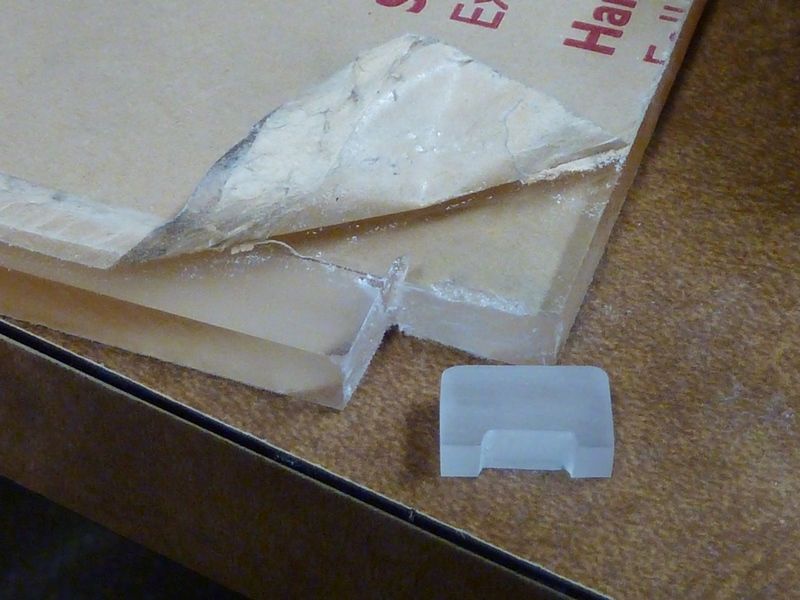
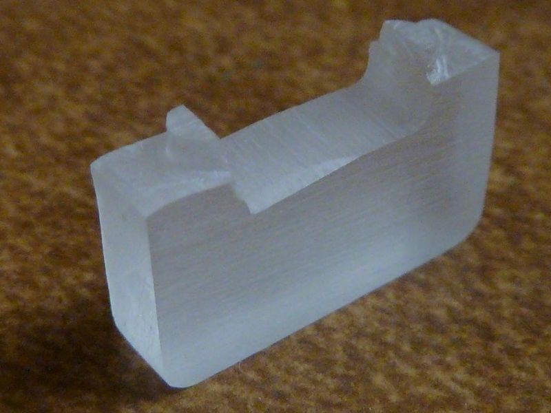
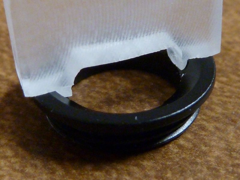
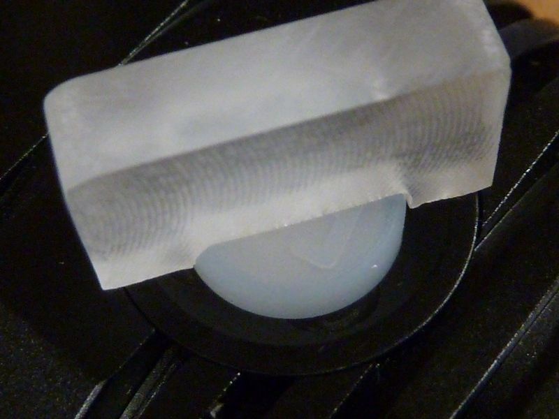
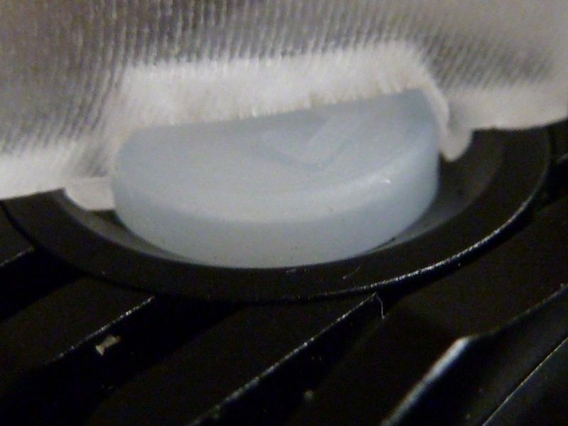
I finished my jig for removing the switch retaining ring, made from Plexiglas:
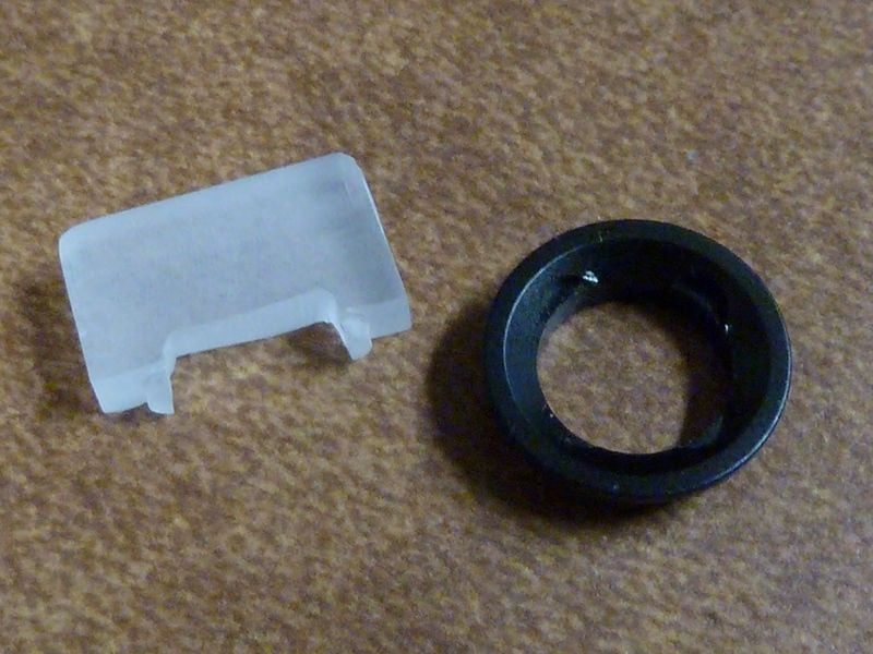
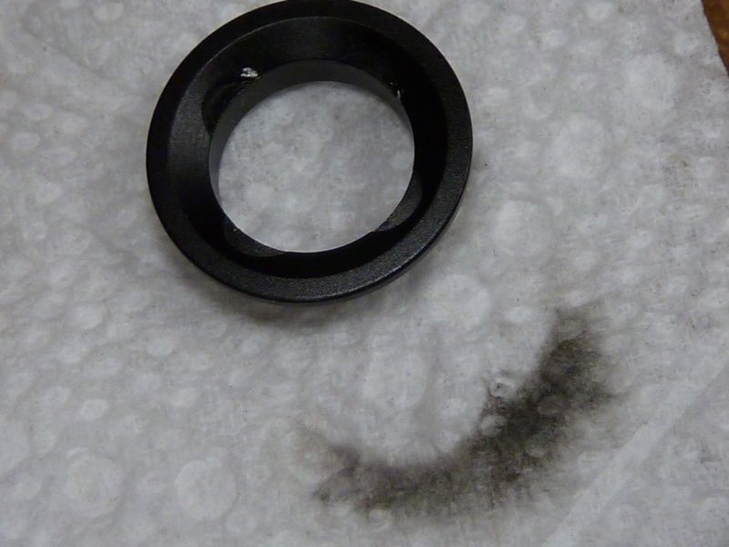
The scratches were uncovered when I wiped the ring down with isop. alcohol on that paper towel - maybe shoe polish?
Otherwise, no marks or damage and the ring was pretty tight in there.
Beautiful work, I like it!
Wow. Nice work in miniaturisation Tom.
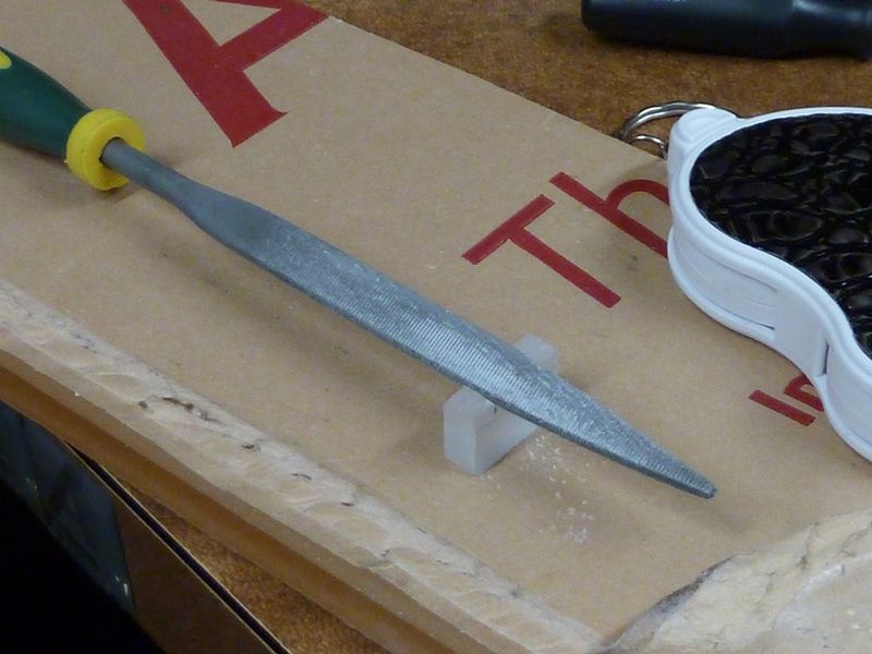
Thanks! It was all done by hand sanding and filing. I like working with that stuff, gets a little messy though. I used smaller files for shaping the 1/2 circles.
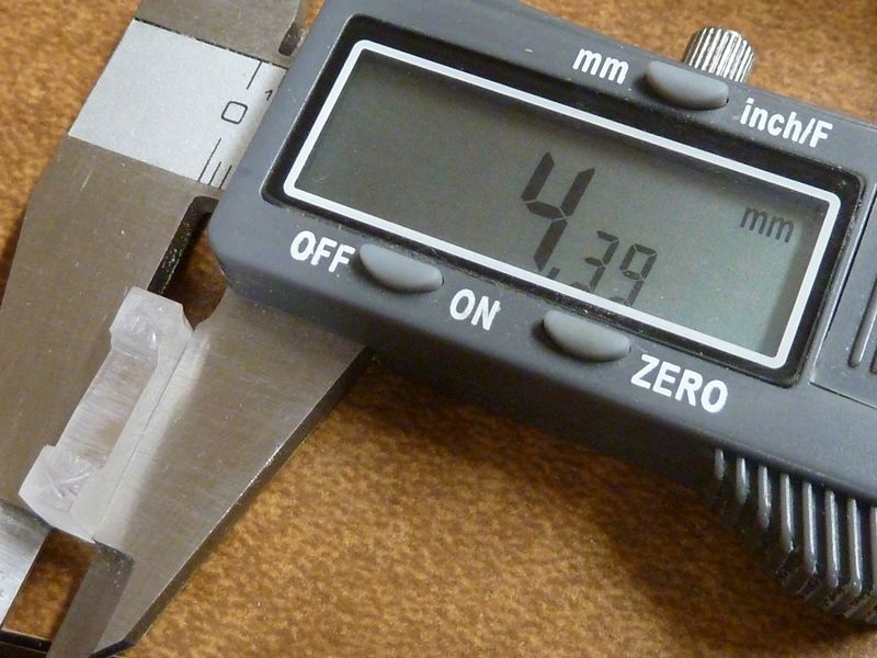
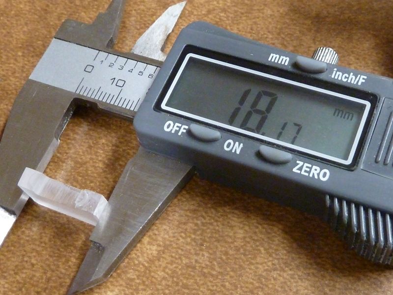
The material started at about 8.25 mm thick from that scrap piece, sanded down to 4.4 mm. A mech designer at work said he'd try 3D printing a jig to fit over the button and fit into all four of the 1/2 circle notches. He thinks the material would hold up, but I'm not sure - it would have advantages to fit in all 4 notches though.
They use SolidWorks here @work, but if it works out, I could maybe make a few available.
You are asking for trouble Tom. I can see it now, 1000 requests for custom built Tom E switch retainer removers. ![]()
Can you please mention it here if you make the project files opensource ?
Thanks
You mean the SolidWorks files? Thinks that's no problem - I'm not familiar with the standards, but think there's standard formatted files. I'll have to ask, but again, he'd be doing it in his free time, favor sort of thing. Dunno for sure if he'll have time, etc., and hope it doesn't take much printing time - it would be pretty small though.
Yes i mean these files .
Not in a hurry at all , one of my friends have a 3d printer and i know he uses Solidworks , so i think it would be awesome to print one too .
Thanks in advance !
I have a printer that I borrow from a robotics team I mentor, and I don’t have it home with me tonight. But I got out my calipers and used TinkerCad.com to make a design. There are two slightly different versions, that take advantage of different properties of how 3D printers work. Give them a try and let me know if anything needs to be changed. Or play around with TinkerCad and make the changes yourself. TinkerCad allows you to download .STL files, which is what most 3D printers use.
The software thinks it should take about 15 minutes to print both of them.
Hello all,
So I got RMM’s nickel plated spring and went to install them today. This was my 2nd time soldering, but I was having a really rough time. Several issues:
1) The solder would form into balls almost immediately when my soldering iron would make contact with the solder. And these small balls would not stick at all. I am using a 2 in 1 wood burner/ solder from harbour freight (I know, cheap). Is that perhaps the problem? Also I am using this solder from MtE (MG 63/37 ).
2) After removing the original springs, there was all this leftover solder and glue type material left over…what is the best way to cleanly get rid of that stuff?
Any input would be great. Thank you in advance!