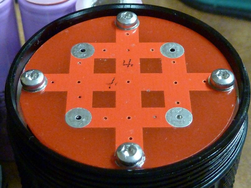
Done right, which it nearly is, conduction through the tube will be better than anything you could achieve with a bit of wire. You can easily measure the voltage drop occurring through the tail PCB, tube, and contact with the driver ground ring, by temporarily running a wire out of the head through the switch hole. Connect it to ground on the driver board, then measure how many microvolts there are between it and the tail pcb when running in turbo.
Edit: actually you wouldn’t even need to fit the test wire, if the switch board has a ground connection (I don’t know which way the LEDs are driven, if high-side then there will be a ground connection on that PCB).
This will quantify any improvements made as you mod things, and it’s a lot more precise a measure than a clamp meter can show you. A clamp meter only shows you the improvement in current to the LEDs, which is a secondary effect of reducing the resistance of the current path, and dominated by the cell internal resistance. Measuring the voltage drop directly this way tells you all you need to know, and when to stop (diminishing returns). You can also directly measure the voltage drop across the battery tube - driver ground ring this way, I suspect that is going to be the real bottleneck, once the tail has been improved.
If you have a clamp meter in the loop as well, you can calculate the overall resistance too.
Try it on a stainless steel bodied torch, and you might be in for a shock. I was amazed at how much worse it was when comparing stainless and aluminium BLF Kronos torches. I thought that thick stainless tube would have negligible resistance, but I was wrong.