No, they’re 0805s but 0603s fit too with some solder stretching. I put a blue 0603 on one side of mine with no problem.
No idea why it became D3, but that is what I see looking back at photos of my prototype.
100 uF across C2 … we do not have a part number for D3, so own risk ![]() . That said, those diodes should be rated minimum 0.1 A continuous and they can usually take at least 10x that in surge. Surge here would be < 0.9 A, fading below 0.1 A in around 1 ms.
. That said, those diodes should be rated minimum 0.1 A continuous and they can usually take at least 10x that in surge. Surge here would be < 0.9 A, fading below 0.1 A in around 1 ms.
FET part number added on the schematic in post 617.
Sounds OK, couldn’t be more than 1A peak, through the (100 mA ?) diode, just worried it might be a bit fragile. Who knows what’s on the board ? If it blows eventually, I’ll just put in a better one.
A bit off topic but do we know if the o-rings are silicone or another material?
I usually assume most lights to have some form of rubber o-rings and not silicone. In my novice experience silicone o-rings usually are not as dark black like rubber and have a sort of see-thru quality to them. I’ve been using Super Lube multi-purpose synthetic grease with no issues. Once I have used petroleum-based grease that was marketed as” silicone,” but it made some of my rubber o-rings swell up and I had to boil them so I could get them to fit after they swelled. So far no issues like that after using Super Lube on my Q8 or any of my other lights. If you haven’t already completely clean the Q8’s threads on the battery tube, and in the receiving ends, then grease it to make it feel 20 times better.
FYI some worst case experimental experience with this little schottkies.
I modified several EDCs with Banggood BLF X6 drivers to OTSM with 2 of this 100 uF caps in parallel behind the schottky without any current limiting resistor in the circuit. Since they are clickys the caps get far more often loaded than in lights with momentaries (where this only happens on powering up). I’m using this EDCs heavily for more than 9 months now, no failure so far.
When testing the Q8 with bumps I first tried a 1000 uF cap in order to see if it helps at all - since I don’t know how long the voltage interrupts last. No damage here either.
Next (and last) try was the mentioned 100 uF cap, so I don’t know if even smaller caps are sufficient.
Hi guys,
I have a rough bit on the bezel of my Q8 that cuts skin and rips clothes. It was suggested to me to maybe try to sandpaper it smooth, but I am worried it may scratch up the bezel and look ugly.
Suggestions or comments?
You can buy very fine grits of sandpaper at an auto supply store. They use them for wet sanding paint, but you can use it for your bezel. Start with the finest grit they offer and see if it has enough bite to smooth the edges. If not, go down a grit and have at it. with sandpaper in the 1000, 1500 or 2000 grits, they will leave a really nice finish on the stainless steel. Good luck.
I just realized that the sandpaper grits may be different in Australia. Do a bit of research to see what’s comparable to 2000 grit in the US.
My wife’s sunwayman c22c had been on in her bag, the side led
It got so hot the lens was melted to some red fabric
I used a file to get it off and then my whetstone to make it nice and smooth
But of course that was plastic lens not stainless, but do you have a knife sharpening set?
I have one which I would use for it makes a wide range of angles possible
+1 - I've used fine grit paper on SS bezels to take some of the sharpness off - came out good. I recently got paper as high as 2000 in Home Depot.
Awesome, I shall look into it
Last night I did my 7th full tail mod with driver screw changes. This was one for a friend who signed up, and ordered a Q8 on his own. He had bought a set of flat top GA cells early on and is using those. So I took a stock reading before the mods, cells at about 4.18v I'm guessing. Only ran it for 15 secs to save from too much discharging the cells.
5,168 @start, 5,000 @15 secs
After the full mods, cells at 4.17V:
6,647 @start, 6,365 @15 secs, 6,260 @30 secs
That's a 29% bump at start, 27% bump at 15 secs. I think the results are this high because the flat top GA cells are pretty short, so not getting much spring compression. Still though, 6,600 at turn on and the more official 6,200 lumens from not quite full stock GA cells is quite good.
Don’t feel bad Tom! I’m glad that you got yours out ![]()
Got those type of screws at home :
But they’re steel, i’d probably better wait for the brass ones to arrive, the steel one will probably be worse then the current ally ones ?
I'm using steel and getting great results. The screw doesn't matter when you properly tin the pad around the screw.
Did you sand off the anodising on the driver end ?
Let's get in sync here -- are you talking about the tail PCB screws or the driver screws? Tail PCB screws are M2.5, driver screws are M3.
I believe the driver screws are to hold done the driver - that's it, they could be plastic and won't make a difference. Electrically, the battery housing contacts the ground ring on the driver - that's how the Batt- signal gets to the driver. The screws don't play a role.
On the tail PCB, you have a nice bare aluminum shelf the threaded screw hole is in. Clean up those 4 little shelves - sand down with 400-600 GRIT to get crud off, then tin the ring around the screw hole on the PCB that makes contact to the shelf. This solves the screw problem, and again, screws could be plastic - it won't matter because you probably have better contact between the shelf and the ring on the driver.
Tinned ring around the screw holes shown here:
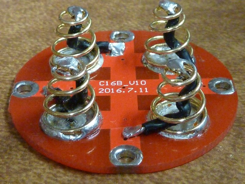
Of course it's important to get those somewhat even for more contact surface. If it doesn't come out flat, fine file will help. They should be tinned because it raises the contact surface above the surrounding solder mask.
Cleaned up shelves shown here. Little piece of folded 600 GRIT paper used, then thin layer of NO-OX-ID:
Would brass screws here on the tail PCB help? Possibly, maybe. But 7,200 lumens on V6 3D LED's using steel screws ain't that bad.
Thanks,
for the tail end I did more or less the same as you, tinned the screw holes, just the bypass (20awg) I have next to the springs instead of inside the springs.
Yeah, I was onfused with the driver end, it’s the battery tube that makes the contact.
Going to upgrade to steel screws tonight, as fitting the alu screws back with the tinned screw holes on the tail end I was stripping the screw heads.