Awesome, I shall look into it
Last night I did my 7th full tail mod with driver screw changes. This was one for a friend who signed up, and ordered a Q8 on his own. He had bought a set of flat top GA cells early on and is using those. So I took a stock reading before the mods, cells at about 4.18v I'm guessing. Only ran it for 15 secs to save from too much discharging the cells.
5,168 @start, 5,000 @15 secs
After the full mods, cells at 4.17V:
6,647 @start, 6,365 @15 secs, 6,260 @30 secs
That's a 29% bump at start, 27% bump at 15 secs. I think the results are this high because the flat top GA cells are pretty short, so not getting much spring compression. Still though, 6,600 at turn on and the more official 6,200 lumens from not quite full stock GA cells is quite good.
Don’t feel bad Tom! I’m glad that you got yours out ![]()
Got those type of screws at home :
But they’re steel, i’d probably better wait for the brass ones to arrive, the steel one will probably be worse then the current ally ones ?
I'm using steel and getting great results. The screw doesn't matter when you properly tin the pad around the screw.
Did you sand off the anodising on the driver end ?
Let's get in sync here -- are you talking about the tail PCB screws or the driver screws? Tail PCB screws are M2.5, driver screws are M3.
I believe the driver screws are to hold done the driver - that's it, they could be plastic and won't make a difference. Electrically, the battery housing contacts the ground ring on the driver - that's how the Batt- signal gets to the driver. The screws don't play a role.
On the tail PCB, you have a nice bare aluminum shelf the threaded screw hole is in. Clean up those 4 little shelves - sand down with 400-600 GRIT to get crud off, then tin the ring around the screw hole on the PCB that makes contact to the shelf. This solves the screw problem, and again, screws could be plastic - it won't matter because you probably have better contact between the shelf and the ring on the driver.
Tinned ring around the screw holes shown here:
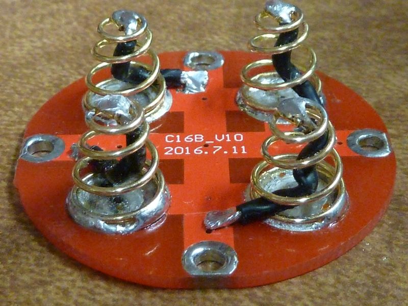
Of course it's important to get those somewhat even for more contact surface. If it doesn't come out flat, fine file will help. They should be tinned because it raises the contact surface above the surrounding solder mask.
Cleaned up shelves shown here. Little piece of folded 600 GRIT paper used, then thin layer of NO-OX-ID:
Would brass screws here on the tail PCB help? Possibly, maybe. But 7,200 lumens on V6 3D LED's using steel screws ain't that bad.
Thanks,
for the tail end I did more or less the same as you, tinned the screw holes, just the bypass (20awg) I have next to the springs instead of inside the springs.
Yeah, I was onfused with the driver end, it’s the battery tube that makes the contact.
Going to upgrade to steel screws tonight, as fitting the alu screws back with the tinned screw holes on the tail end I was stripping the screw heads.
Many thanks. Looking again at DEL’s schematic I think has amended R6 to 4R99 (maybe I mis-remembered it as being being a bit lower) so surge of max. 850 mA or so. And only when batteries first fitted (not a clickie design) as you point out. And surviving 200 uF with no series resistor in your clickie torches is very reassuring.
Difficult to analyse how much charge the MCU needs to hold it up, for how many milliseconds (need to know what power interruptions look like, experiment called for ?)
You could estimate the length of a power interruption by measuring the spring stiffness (use a scale, and measure e.g. force needed to compress spring by 1cm), and weigh a cell. Then calculate resonant frequency of a spring with a mass on one end. One half cycle might be in the ballpark of a typical power interruption, but it also might bounce a few times more.
I anticipate the major current demand will be from driving the gate of the FET when PWMing it, and that’s not easily estimated (need at least to know PWM frequency and gate charge). Easiest just to ’scope MCU voltage and see how it decays after power disconnected and take a view on that. Or ignore my theorising and just use your 100 uF ![]() .
.
I think worst-case might be: heaviest cells, weakest springs, lowest battery voltage, torch operating in a FET mode with highest frequency of PWM (does it vary ?).
PWM frequency is the same, regardless of FET, 7135, or range. Think about 15K.
I use 4.7 ohms for R6, not sure if 4.99 makes much difference? Most of these resistor values have a valid range.
One of my favorite choices for metals is this eraser type grit impregnated sanding blocks. Comes in 3 grits. Will take rust spots on cast iron out, all the way to polished. Good stuff.

I think the main purpose of R6 is to isolate the MCU supply from noise/inductive spikes/ringing etc passed into the main supply rail from the heavy FET switching transients, LED board lead inductance, etc. In combination with the standard 100nF decoupler on the MCU it acts as a high frequency filter. Adding a big bulk decoupler can probably only improve this, depending on high frequency characteristics of the type of cap. used.
The chip ceramic 100uF Flashy Mike has used looks well suited here.
Using instead e.g. a small leaded electrolytic, might actually make the filtering effect poorer, despite being good for holding up the MCU.
Reducing the value of R6 too much might also reduce the effectiveness.
I seem to remember that adding R6 turned out to be quite important during the development, and solved some strange issues that can afflict earlier FET drivers which don’t have it, particularly when tuned to the max. driving very heavy LED currents. The Attiny13 also seemed to be more tolerant than the later versions in this regard.
Is there any internationally available NO-OX-ID equivalent?
Dunno, sorry. It's a conductive grease, so sure there are equivalents out there but think they can be costly.
For that small 4.7/4.99 resistor, according to DEL and what he saw on the scope, that was the most important change to get the ATtiny85 working reliably. Our old standard circuit for the 13A did not work reliably with 25/45/85's. Richard with his 25 based Mtn boards went in a slightly different direction, still works but I can't argue which is best. Just with DEL's, he's posted all the evidence on what it did to cleaning up the spikes, signals, etc.
For a while I was doing cut/jumper mods and tail-standing components to jury rig up Mtn boards to have that resistor where it should be, before the diode, but then OSHPark boards came out in all sorts of configs and sizes.
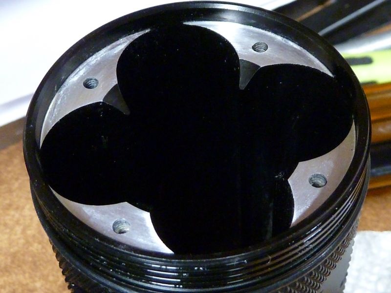
Plan changed. Below is a photo of a coil of a be-cu spring pair over the existing springs. Near perfect fit. After cutting the coils from the pair I’ll bend the ends to align with the straight ends of the existing springs and apply a bit of solder at the base and tip.

edit: I checked on ebay hoping to acquire more and post a link but rhey’re no longer available. Fortunately I have 2 pairs.
Quick and dirty analysis, FET datasheet has total gate charge 21.8 nano Coulombs.
At 15 kHz, that’s 327 uCoulombs x2 per second to drive the gate high and low i.e. about 0.7mA (which is lower than I would have guesstimated).
Add on current drain of MCU when firing on all cylinders, dunno, first figure I saw on the datasheet is 300 uA at 1 Mhz. As I thought it’s the FET gate drive that dominates.
The switch LEDs aren’t on, so ignore them.
So maybe we have as much as 1mA total current drain to hold up through a jolt to the torch (nice round number, and not sure I trust my 700 uA calculation).
Are we using Attiny 85 or 85V (lower voltage). Or is e.g. brownout detection in use, I don’t know. Lowest votage might be between 1.7 and 2.8V, I’ll choose 2.25, and cell voltage of 3.0, minus Schottky drop, say 2.7 V.
So max. allowable voltage drop during interruption = 0.45V
Thus therefore, (Capacitance = Coulombs per Volt, Coulombs = Amps x Seconds)
Draining at 1mA the 100nF decoupler can only hold up the MCU for about
100nF x (0.45V / 1mA) = 45 microseconds ![]()
No wonder it doesn’t like bumps.
Whereas a 100uF cap. can hold it up for 45 milliseconds. ![]()
That seems pretty clear to me, as a SWAG, even if I’ve got the numbers badly wrong, we are comparing tens of milliseconds (good) with tens of microseconds (bad).
Use a diamond sharpening rod at a 45 degree angle, I do that to all my lights on the inside edge of the tube where batteries are inserted…
I think the “magic ingredient” of things like NO-OX-ID might be something that cuts through pre-existing tarnish and maybe keeps on doing so.
Otherwise anything that seals the contact surfaces from the air, like car battery terminal grease, plain silicone grease, even Vaseline, will be a great help in simply keeping out air from the mating surfaces and minimising the chance of later oxidation, both of which solder and bare aluminium are prone to. I think any of these would be better than nothing, long term.