Ok, I’m not much of a modder but this I think I got.
Springs are bypassed and all screws, apart from the one holding the reflector, has been replaced.
It’s been cleaned up and everything makes much better contact now.
The reflector has been turned like .5 - 1 mm for better centering of the leds.
Have only tested it for a very short time in the back yard and it’s hard to say how much brighter it is, but it sure is getting hotter.
Before mod the light was warm, but not hot, after three minutes when it stepped down.
Now the head was to hot to touch and the body was quite hot too.
The light indicated 60 degrees.
So…
How can I measure the current being drawn?
And what’s the highest temperature before causing any damages?
Once you start modding something as potent as the Q8 you are on your own.
If current draw is of interest, best mod the tail pcb to put in a clamp meter loop. Of course you will need a clamp meter also.
Once it gets too hot to hold, turn it down.
There is no temperature “before causing any damages”, well, until you start melting the solder. The harder you drive the LEDs beyond specification (current and temperature) the faster they will degrade. From 1000s of hours to just a few. Modders realise this, accept the compromise and will replace.
As supplied (particularly no spring bypasses), it should be very reliable, last almost forever, and operate in a safe efficient region where LEDs and cells perform at their efficient best and still put out loads of light.
It is not compulsory to immediately crank up a well balanced torch just because you can.
You have already observed how much hotter your’s runs than standard, that should be a strong clue as to how much additional stress it is getting.
I know I have another set of loaded lbe here somewhere - one is standard for use with a normal molle pack and the other is ranger style suitable for use with a ‘chute - and I know some had FSNs on them. I bought like 8 of these M4 pouches years ago when I pieced together a near complete molle set with gen IV frame. In some ways ’more than complete’ might be more accurate. Previous generation pack and shoulder straps required mods and fabrication of lashing straps and a bit of ingenuity to make it work.
On my own? That’s what I thought this forum was for. So I wouldn’t be on my own. Therefore the questions.
And I know I don’t have to do anything with this light, but it’s fun and a way for me to learn.
Of course the higher levels of current and temperature eventually will effect the LEDs, and when/if that happens I guess I’ll have to learn how to do a LED swap.
Until then I’ll be happy with this as it is now, and maybe buy me a clamp meter.
I believe the “on your own” comment meant that as you tweak and mod and push the light, you’re dealing with much more power running through the wires, traced and components and that can lead to unexpected results. When it’s in your hand and chugging away with all of those amps, the forum won’t matter much as you won’t be able to quickly get the answers you need as the heat builds up and parts can potentially fail.
Sorry if “on your own” came across badly. I meant that once you start increasing LED current etc. seemingly minor things can have major effects, e.g. how well the thermal paste has been applied under the MCPCB, how well the LEDs have been flowed onto it and whether the direct thermal path soldering is perfect, quality of LED wire solder joints, etc.
This is where what works for one person may not work as well for you.
The question of “what’s the highest temperature before causing any damages?” is unanswerable, and anyway depends on where the temperature is measured. If referring to the temp. sensor in the MCU, it is only incidentally related to e.g. LED temperature, and then only under steady conditions.
The first step of bypassing the springs should also be done knowing that you have removed any protection from e.g. accidental reverse fitting of a cell, or poor contact so that e.g. worst case only one cell is actually in contact and taking the full load of a high current modified torch, etc. and safe use is now entirely your responsibility.
No worries.
Got it, and I’m aware that higher current not only brings more light but also could cause unexpected issues.
If it goes FUBAR on me and I can’t fix it I guess I’ll buy a new one and call it a lesson.
I’m rather careful regarding my cells so I hope that won’t be an issue.
I also have a few modified lights, some by me and some by others, and I sure won’t let anyone else use them. Just don’t trust people… :person_facepalming:
Plenty of data on where LEDs are running at optimal current for efficiency, e.g. lumens/watt. Djozz’s measurements particularly. Of course they get brighter, sometimes much brighter, beyond there, but as efficiency drops, more and more goes into heat, less and less into light.
To run ordinary LEDs at efficient current levels at say 5000 lumens, takes at least 4. I think the Q8 as supplied is right on that cusp.
If you have 18, say with efficient buck drivers, it is super-easy, but that is a different torch.
No point denying facts, the Q8 has 4 very good LEDS, MCPCB, driver, reflector, it all works superbly, and can be tweaked quite a bit beyond there.
4 XML2 or XPL are perfect for 4000-5000 Lumens plenty lights with acceptable efficiency
With ramping you have still a acceptable efficiency with low FET brightness, but you have so much runtime at 1-2A efficiency doen not matter too much
Same for XHP70 and 70.2 LEDs
It also depends how big your batteries are, for the GT you can use 8 18650s with 2500 lumens near the point where the max. lumens point for the XHP35 LED, of course not very efficient, but plenty of runtime
For lights with 10440 or 14500 efficiency is more important as your battery capacity is very limited, but still hot rods with short bursts of massive light still have their place, even if they have crappy runtime and heat problems
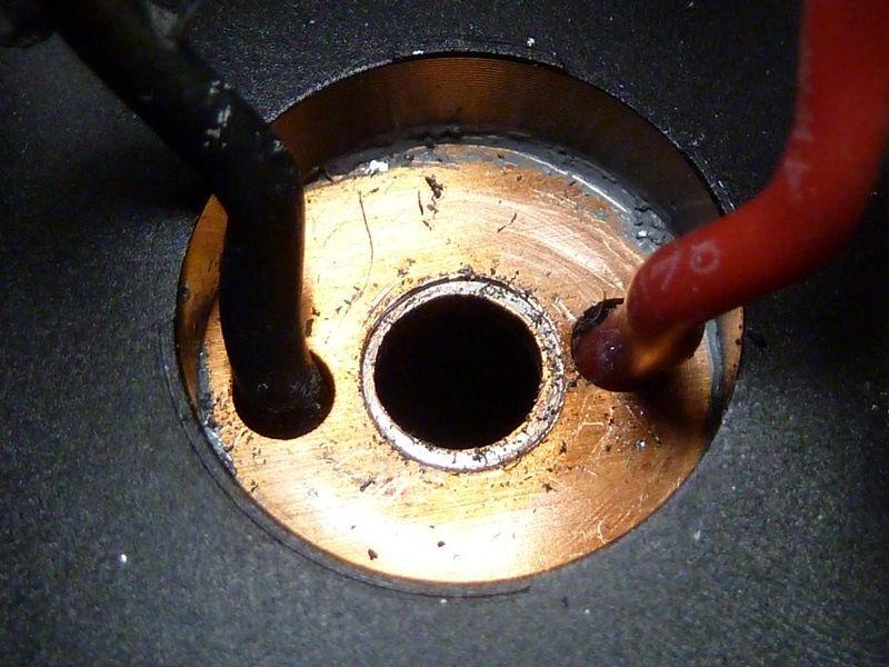
Fixed the stripped reflector screw. Drilling it out worked well and quick. Once the head was off, stem was easy to unscrew:
They had the screw tightened down pretty well. The 1.95 mm thick MCPCB was bulging up in the middle on the LED side, checked with a straight edge, but hammered out flat now.
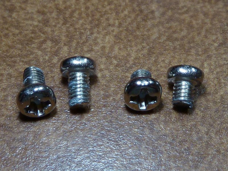
When I finally was able to take apart the head with getting this screw out, one of the screws holding down the MCPCB just fell out. The holes for the screws holding down the MCPCB were not threaded. The M3 screws appeared to be cut off to about 2.75 mm where other good Q8's use 5 mm length panheads.
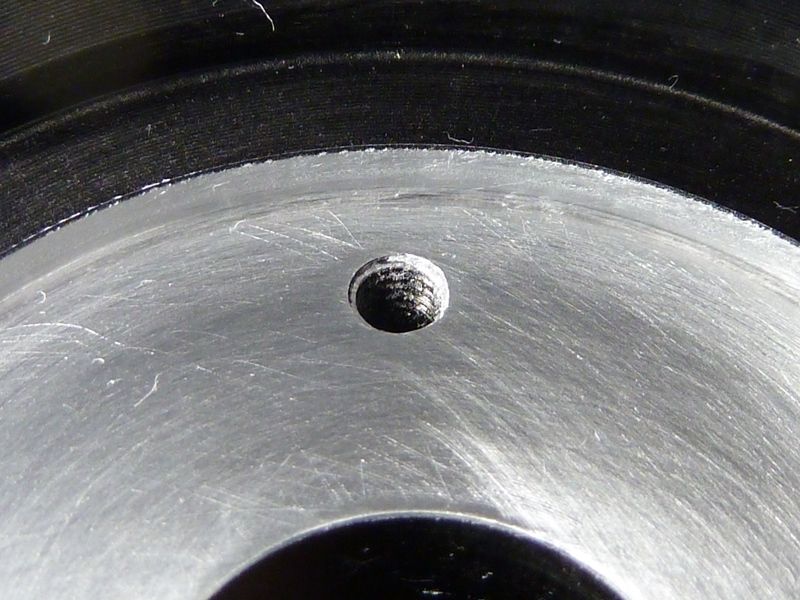
Here's a good stock Q8:
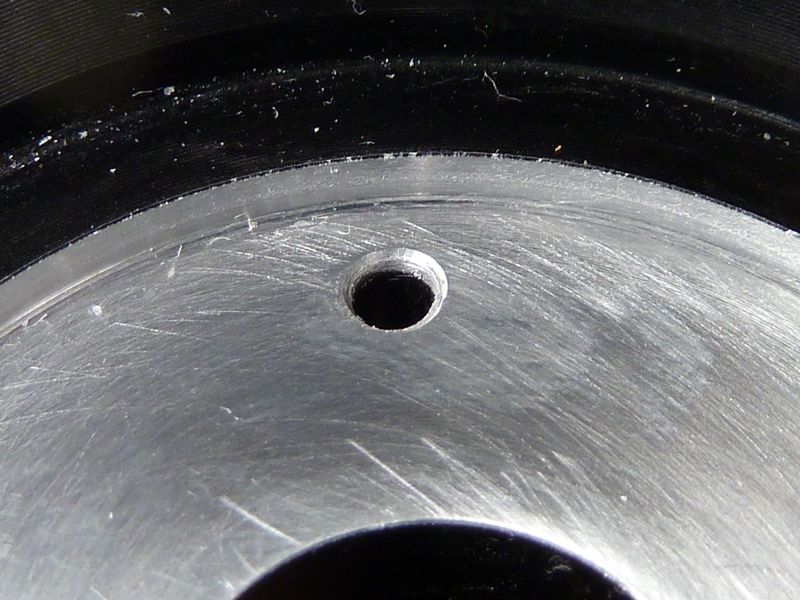
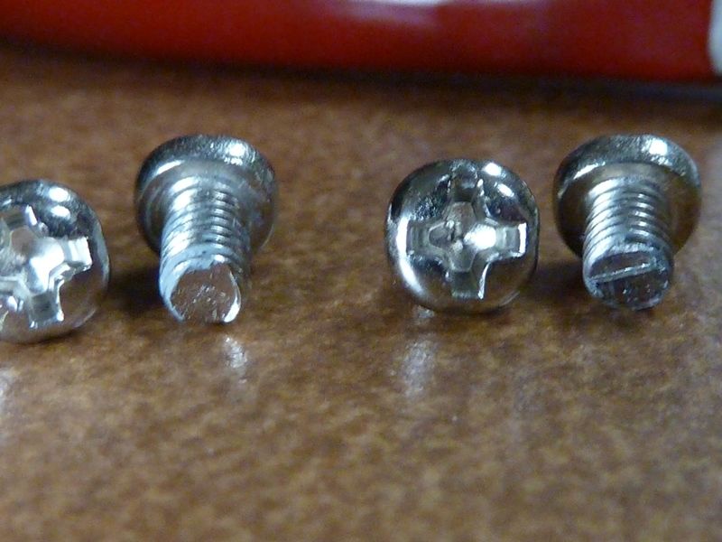
Here's the bad one. There's no threads in that hole at all. The screw being cut down seems to barely hold at the lip, if at all. The MCPCB is ~1.95 mm thick, depth of screw threads about 2.75 mm, so not much to bite in to:
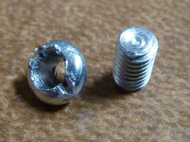
The good stock screws on the left, the bad unit's stock screws on the right:
It kind of looks like the screws on the right were cut down to size:
Just thought I'd post this for something else to look out for. If your screws are under 3 mm on the threads, you got one! I haven't even checked the head/LEDs/MCPCB before giving out a whole bunch of Q8's, so I don't know how many 1st batch lights went out with these issues from my batch.
I can fully understand though why the production/assembly supervisor was fired over the Q8 though... :FACEPALM:
On the 2-3 Q8's I've seen so far with the MCPCB out, they used a lot of thermal grease, maybe too much, bit every square mm of contact surface is covered at least.
And I know Tom is really really tired because he called the Metal Core Printed Circuit Board an PCMCB. Tom, I think you deserve to take a weekend off and go fishing.
Oh that is a pity. Maybe the operator stripped out the thread in the shelf. With the screws cut down so short there will have been almost no thread in there, by the time it is through the (2mm ? thick) MCPCB. Is the hole otherwise fully threaded below ?
I think these two screws are quite important for holding the MCPCB in good thermal contact with the shelf. Otherwise the only pressure holding it down is from the bezel + glass + o-ring at the front. This works OK on my “Kungs” but they have no shelf.
Thinking about it more, it would be better to use a longer central fixing screw inserted through a “bridge” piece of metal, so that it tightens, via the bridge, against the rear of the shelf, not the MCPCB.
This would clamp the whole head together, the MCPCB would be firmly clamped down between the reflector and emitter centring rings, and the shelf. There would be no force on the MCPCB causing it to dish in the middle. These two screws would be less essential for thermal reasons, just locators to keep the MCPCB in proper orientation.
The Q8 I' working on now is getting brass screws all the way - got them in the other day -- will post pics. Even the 6 mm long brass 3M's fit perfect to replace the 5 mm long MCPCB screws.
I swear I type this wrong every single time, and have to go back to correct it. I'm also a king of typos, but I try to proof read before "Save", but I always mis thins.
Ohh - really miss offshore tuna and albacore at the canyon. Used to go every weekend in season. Blue, clear and warm water out in the gulf stream 70 miles or so out. They used to call me "The Surgeon" because I'd bring my own set of highly sharpened knives, and would meticulously clean, gut, fillet everything and anything we caught. Really miss that...
I can imagine a conversation, “Boss, some of these Q8 heads don’t have threads for the MCPCB holddown screws, should we send them back for re-work or tap them ourselves ?”
Boss: “Naah, just clip the screws short so they are just the heads, and glue them in to the MCPCB, nobody’ll ever notice” “And make sure you crank down the centre screw so hard that it’ll never come out again” etc. etc.
SinkPAD has MCPCB’s in a unique Star shape, with extra pads for connections that comes in handy sometimes. We used to just call an MCPCB a “Star” because that’s what we most often saw. Then the 16mm versions were just round and the Noctigon’s were all round, so Star became more or less obsolete.
When SinkPAD changed to the version II they made the copper/aluminum back smooth (the original had a slight rectangular indention where they punch the metal up for a smooth thermal pad on top), but the thermal pad is slightly recessed on top. I was dealing with SinkPAD directly at the time and bought the last 200 original star pattern XM footprint boards they had in stock. Wouldn’t you know that Cree then came out with the XP-L variants and I seldom use XM footprint anymore. lol