Could these be realistically offered in kit form? Chances for EU fellows to acquire at reasonable money?
How about a buck-boost driver? It is amazing you've handled to fit this boost engine over just ∅17mm, could we see a ∅20mm 1S emitters buck-boost engine in a nearby future? In obtainium materials, :-) of course.
The GXB20 you made had a circuit diagram along with a detailed bill of materials. Would you be able to do the same for the GXB172 because I would love to see how this driver works in such a small overall size. Please feel free to contact me at my email: jasonlee422001@gmail.com
Since you're planning to drive a XHP70.2 with two cells, I'd highly recommend making a linear constant current driver instead, with an optional direct drive mode (though personally I don't like direct drive FET drivers). The GXB172 is a boost driver and boosts up the voltage from a single cell to the 6-7V required to drive quad-die LEDs like the XHP50/70 etc. However since you're using two cells, there's no engineering benefit to make a boost driver.
I'd recommend keeping the two cells in series, and you can design a high current but regulated current driver. This can be done with a feedback mechanism using a pass-FET, an opamp, a current sense resistor, and some sort of control (e.g. via a Microcontroller or potentiometer) to generate the desired reference voltage for the desired current.
I do not have any schematics for the GBX172 yet because it's still in development. That said, there's really no secret or magic to it - it's essentially a synchronous boost converter, and if you search that you'll see tons of the exact same schematic online. I'm using the MP3431/29 IC, and if you look at the datasheet, you'll see the full reference schematic. Likewise, check out the TPS61088 if you're interested in boost drivers.
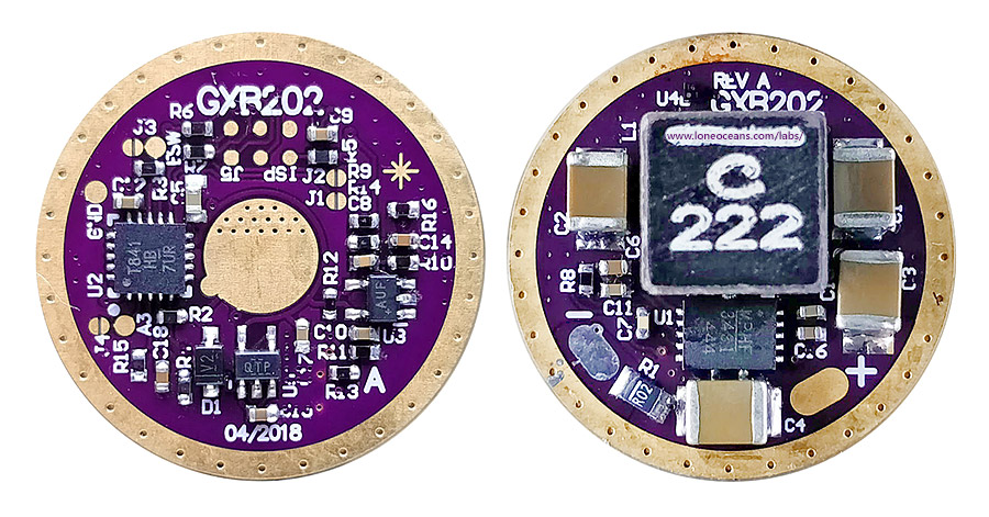
Quick update... if you recall, I started the GXB driver project with the original intention of putting a XHP50 LED in one of those chose SK98 flashlights. Since those hosts come with a zoomy lens at the front, I thought it would be a perfect candidate for a XHP35HI for a low cost but pretty decent thrower. The SK98 requires a 20mm driver and a 20mm MCPCB.
I didn't have much time to do much but I did do a super quick modification of the GXB172 and... here's the GXB202!
The larger board size allows for much better clearance around the board as well as more space for larger passives.
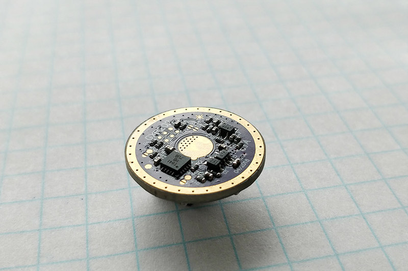
Here's another view of the driver board after assembly.
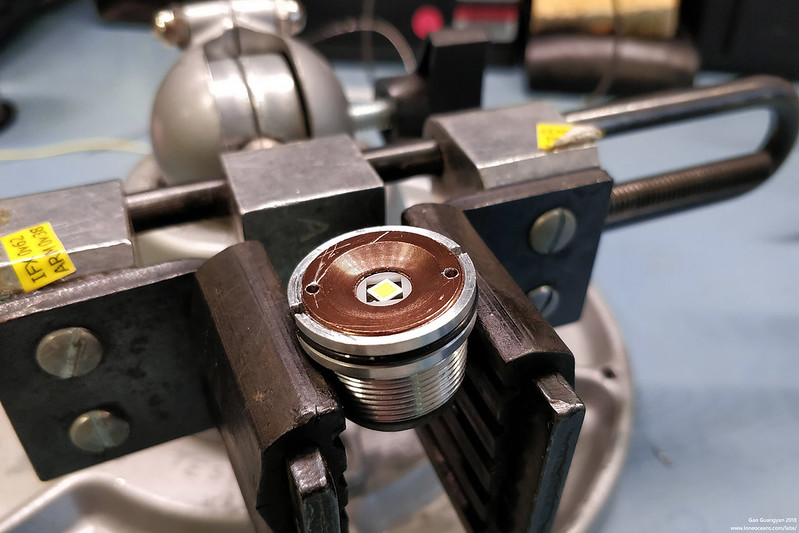
For the LED, I chose the highest bin XHP35 HI I could buy (sadly only a D4, 5000K). This was installed into the pill with Arctic Silver thermal paste on a 20mm copper MCPCB.
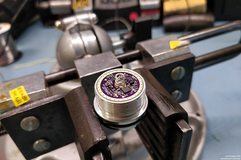
And the driver was also installed. Note the GXB202 was configured for 12-14V+ output with a maximum of 2.5A drive. TA measured 2570 lumens from a E2-bin LED at 2.5A, so this should be putting out a good ~2396 lumens.
I then put the light together with some improvements to the tailswitch and paired the light with a LG HG2 cell, and the driver works great! More to come soon.
The GXB172 hardware has been ready to go for a while :) . The moonlight mode could be better though, so the main thing left is essentially just the firmware and some tweaking is required (e.g. thermals). Texas_Ace has a GXB172 fitted into his own light for testing. I don't have as much time as I'd like to work on the firmware ><, so it's certainly somewhat of a concern for me since I think people do want a proper Narsil or Bistro/Biscotti etc port.
I'd love to use beryllium copper springs but yep the ones that I can buy are too big for this driver, and I'm not sure how much demand there will be for custom made smaller copper springs. Besides, a spring bypass although not as neat, works very well. Anyway for this particular build, I used a nice phosphor bronze silver plated spring, so that should be fairly decent as well.
Yeah, hopefully we see all the Loneoceans drivers selling soon. (EDIT: and the tail pcb’s of course.) But, this driver is the biggest deal, because it’s something we’ve been asking for around here for quite a while. We’ve actually been spoiled for choice with linear and direct drive style drivers. We needed a high power boost driver! :partying_face:
Still on the list: high power programmable buck driver. Richard had designed some, but he ran into problems when he tried to scale them to other sizes. He still sells them in two different sizes, I think. And although I’m sure he’d do it if one were to ask, he doesn’t officially offer the latest BLF firmware choices on his drivers.
Yes, I got one of his drivers for testing a few weeks ago, I found a few minor issues, mostly with the firmware and let Loneocens know but have been too tied up with the MT09R, GT’s and Lumen spheres (which I still have a few left BTW) to really mess with it much more thus far.
The hardware is indeed looking very good, I have several plans for such a driver once the firmware is sorted out. Ideally I would like to see Narsil or bistro firmware ported over to keep the “standard” firmwares that most of us are used to at this point but the firmware he is working on is not bad, just basic.
The thermal regulation is better though.
This is on my list of projects once I finishes a few I am working on now.
I don’t know about all the E need but I could sure use one or two. Building a light up from scratch makes the multiple-cell usage problematic, or for me it does anyway, and I’ve been doing some testing on the 12V XHP-35 so yeah, a good driver to boost from one cell to run the 35 at 2.5A or so would be fantastic!
I could even build it myself if provided a parts list and a Gerber file so I can get a solder paste mask made. Would need the .hex file to flash it of course. I’m game though, if G wants to help me out….
Considering the above (from the OP) what about 2S to a 12V emitter? My thinking is that it still needs a boost driver, because the 2S voltage isn’t enough for that, and if the host is already made for 2S anyway, why not use it? Also I’m hoping that this driver can stay in regulation longer at max output with 2S input than with 1S input. (Stands to reason, right?)
So, what is meant by “if the right Vreg/LDO is used”. Does the driver already use a Vreg/LDO or would one have to be added? Also about that “and firmware written to take advantage of this”. Will the firmware need to be changed between 1S/2S or would the same firmware be able to do both/either?
Here’s where I’m thinking of using this possible scenario. I have some cheap zoomies with extension tubes. The driver is actually a buck, feeding a 3V emitter. That way, 1S and 2S Li-Ion are both possible, and also 3xAAA and 2x(3xAAA) with the included battery holders. So, if this driver could give the same flexibility to a 12V emitter in this host, it would be a simple upgrade. Just switch the driver and the emitter, and it will work. Will it work?
Using 2S for 12V LEDs is way better for the boost IC. It then pulls less current from the cells, for the same LED current. But on the other hand, DC bias on the ceramic input capacitors is way worse on 2S configs. And on the output with up to16V it’s even worse. A 47uF capacitor then has about 5uF.
Depending on the input and output voltage, you might need to change hardware, for example the voltage divider for battery voltage, so you can avoid reprogramming by changing hardware. And depending on your output current ripple demands, the inductor (and maybe even capacitors) need to be changed as well.
Tell Mouser to stock these high capacity caps that I need faster, then I could work on it as well.