Multimeter and component testing
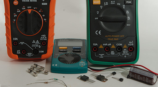
One application for multimeters is to test different types of components, some of the test are fairly easy, while other requires a bit more knowledge and there is always a few pitfalls.
My examples are with fairly large leaded parts, they are the easiest to take pictures off, but the test can also be used on other sizes of parts (Like SMD).
I use a couple of different meters, sometimes to show something, other times just to show that the actual meter is not that important as long as it supports the function.
Fuses
Incandescent lamps
Resistors
Resistors, low-ohmic values
Resistors, high-ohmic values
Capacitors
Diodes
Leds
Transistors
Transistors again, BJT types
Transistors again, MOSFET types
Other
What to look for in a multimeter
Alternative ways to test components
Notes
Fuses
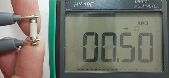
For fuse testing the best range is continuity, but ohm can also be used. It is best to remove the fuse from the circuit before testing it. To test it just touch the two ends with the probes, it do not matter what end you use the red and black probes on, fuses do not have polarity. The buzzer in the meter will sound if the fuse is working and the displayed value will be a fairly low ohmic value (Fraction of an ohm to a couple of ohms).
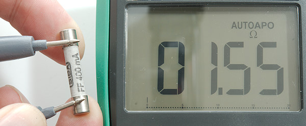
A typical multimeter mA fuse, it is ok. These fuses do have around 1ohm (Here 1.55ohm) and adds significantly to burden voltage in the high mA range.
A 0.1A fuse that is working.
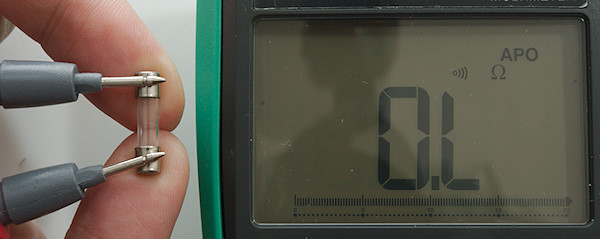
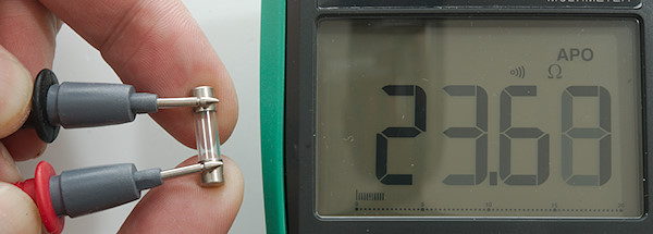
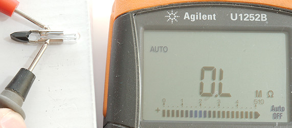
This fuse is blown, in continuity the meter will show OL in that case and there will not be any sound.
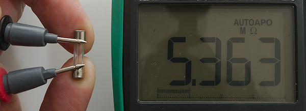
But if you are using the ohms range it may show a high value instead, how high depends on how dry your fingers are and how hard you press them against the fuse/probe tips.
Incandescent lamps
Incandescent lamps will probably soon be a thing of the past, but for now they are still used in cars and as indicators (Mostly older, LED’s are much better for this task) and for some special applications.
Testing them are best done in ohms mode (Continuity can be used for some bulbs).
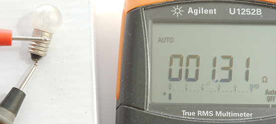
Measuring resistance between the two terminal, there is no polarity. For high power lamps it can be close to zero.
This value cannot be used to calculate the power (watt) of the lamp, the resistance of incandescent lamps will increase dramatically (like 15 times) when the filament changes temperature from around 25°C to 2200°C .. 3200°C
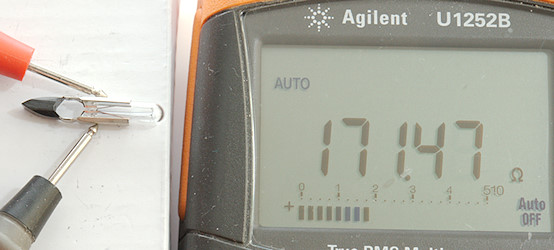
A signal bulb, this is very low power and has a high resistance, a continuity test would not work for this bulb.
A blown bulb, if I had touched the probe tips the value would have been lower (Se last image in fuse section).
Resistors
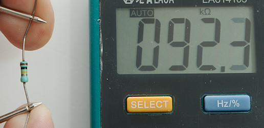
Resistors are very simple to test, put the meter in ohms mode and connect the probes to a loose resistor, then read the value on the display (This works most of the time).
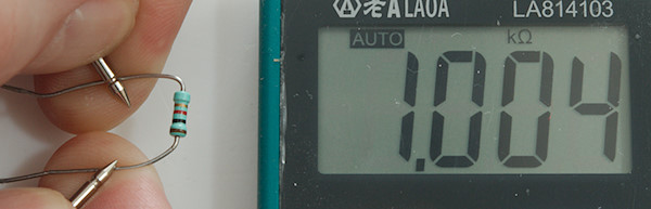
A 1kOhm resistor
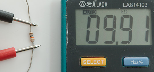
A 10kOhm resistor.
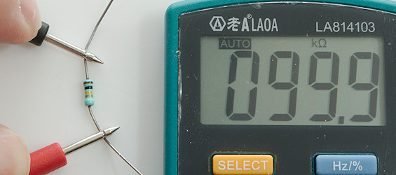
A 100kOhm resistor. This resistor looks to be out of tolerance, it is marked as 5% and I measure considerably lower.
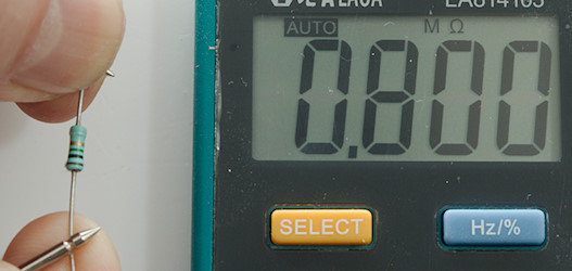
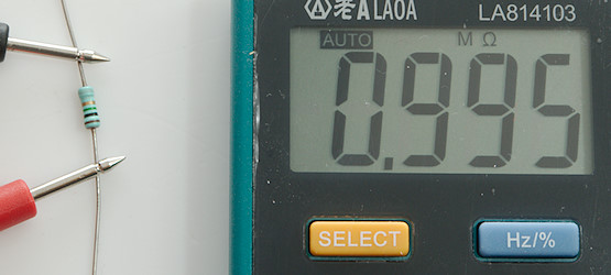
A 1Mohm resistor. This is 20% below marked value, could I be doing something wrong?
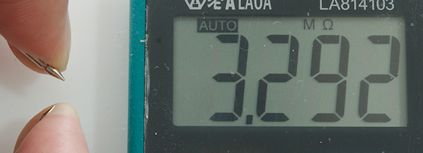
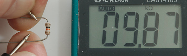
What about a infinite resistance, i.e. no resistor? I get 3.3Mohm, that is very far from infinite!
The problem is that I am touching with my fingers, the path through the human body is not anywhere near a infinite resistor, if you are sweaty it can easily be as low as 100kOhm, the body is only about 1kOhm, the high resistance is due to bad contact on the skin. Pressing hard will reduce the resistance.
Measuring the correct way, i.e. without touching, the 10Kohm resistor is slightly closer to 10Kohm.
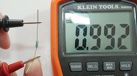
The 100kOhm is easily within its tolerances now.
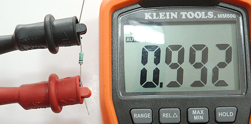
Same with the 1Mohm resistor.
There are other ways to get around the body resistance, here I am only touching the resistor on one side, because the other side is isolated it works fine.
Or I could use alligator clips and not touch the resistor at all.
Measuring a resistor in-circuit with power off, may sometimes work, but often it will not because some other resistors or components will affect the result.
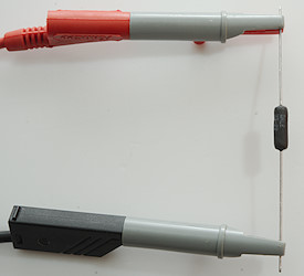
Resistors, low-ohmic values
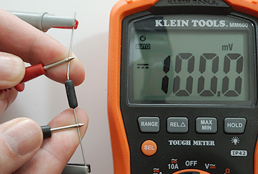
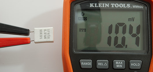
Another problem is measuring low ohmic resistors, here I measure a 0.1ohm 1% resistor. It do not look to be anywhere near 1%.
There is a reasons for that, it is called contact and cable resistance. Here I measure with both probes on the same side of the resistor. It will not show a 0 on this meter with 0.001ohm resolution.
Pressing the “Null” button, this is also called REL on some meters (
 symbol on display) and measuring again gives a significantly better result, but a normal ohmmeter is not the best tools for measuring low ohmic values.
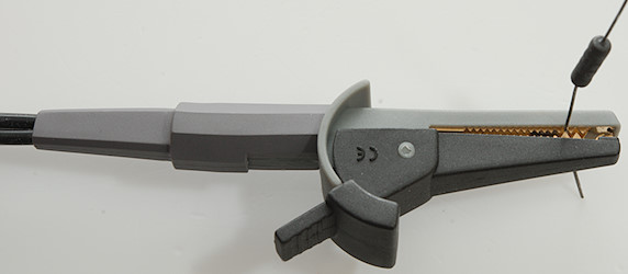
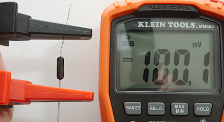
If you really want to measure low ohmic value, the solution is 4-terminal equipment. On these jaws the upper and lower jaw is connected to different cables and the two parts of the jaws have no electrical connection.
This means I have two plugs from the jaws.
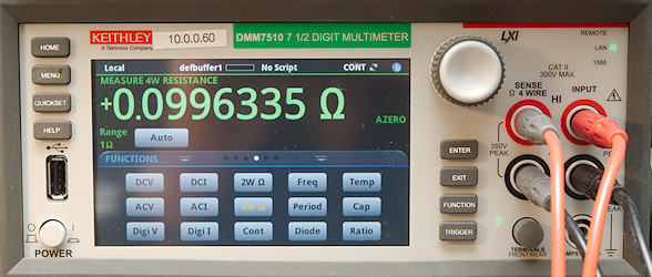
And with a proper 4-terminal meter I can measure the resistance. There will be some variation depending on where I connect the wire on the leads.
There are cheaper ways to make 4-terminal measurements:
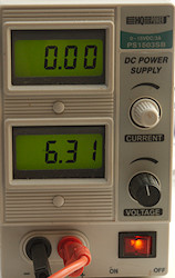
A lab power supply with adjustable current limit can make it fairly easy to check low ohmic resistors.
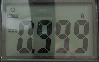
First I adjust the current limit to 1A using a multimeter, it is more precise than the meter in the power supply. The voltage is not important, a few volt is more than enough for resistors below 1ohm.
When doing the test I keep an eye on the power supply meter to check that everything looks correct, i.e. it is delivering 1A.
I connect the power supply to the resistor I want to test. Now the current in the resistor is 1A.
A check with a voltmeter across the resistor will show the voltage, that is the same as the resistance, i.e. 100mV is also 100mOhm or 0.1ohm (As long as the current is 1A).
The 4-terminal wire from above can be used with this solution, making it much faster to check many resistors.
I have one wire from each jaw connected to the power supply, the other wire to the meter.
Here I check a 10mOhm resistor.
The only problem with this solution is how much power the resistor can handle, at 0.1ohm or lower the power is low enough, between 0.1ohm and 1ohm some non-power resistors may be overloaded, above 1ohm the 1A current is for power resistor. Reducing the current to 0.1A will reduce the power and the displayed value must be multiplied with 10.
Resistors, high-ohmic values
What about resistor at 100Mohm or more, how are they measured? There are basically two ways, either make the meter very sensitive or increase the test voltage. When working with these kind of values humidity can easily affect the result, fairly dry surroundings are important.
For testing these resistor I do not use probes, but more fixed connection where I can keep my fingers away, with the first meter due to noise, with the second meter I also have to be careful with the voltage (The meter probes are designed for this, but do not use fingers to press the resistor against the probe tips, this would also spoil the measurement).
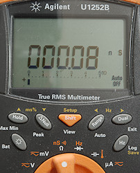
Some meters can measure nS (nano siemens), that is 1/Gohm, i.e. 1nS is the same as 1Gohm and 0.1nS is 10Gohm.
Just because a meter can show nS, do not mean it can measure very high values, but most can. On the above picture nothing is connected to the meter.
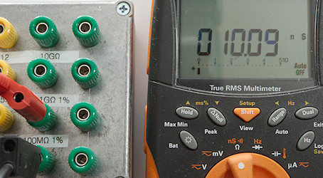
A 100Mohm resistor is easy enough to measure: 1/10.09 -\> 0.09911Gohm or 99.11Mohm
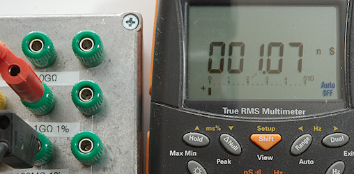
A Gohm also works: 1/1.07 -\> 0.9346Gohm or 934.6Mohm.
The 10Gohm resistor looks like a lost cause, but it is not.
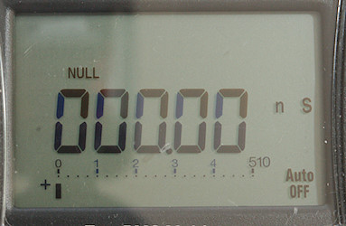
First lets use the REL/NULL function. I had to use a non-conductive stick to press the button, the setup is rather sensitive.
With Siemens the value for parallel resistors can be subtracted and added, like Ohm can for resistor in series.
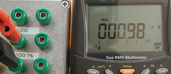
It did improve the result for the 1Gohm resistor: 0.98nS -\> 1.02Gohm
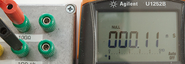
The 10Gohm gives 0.11nS -\> 9.091Gohm, it is fairly close.
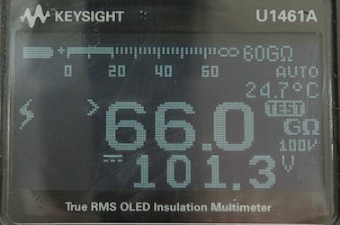
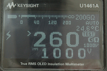
Lets look at high voltage instead, this is an insulation meter to check if insulation works correctly. It can test with up to 1000V (Be careful with your fingers). At 100V the maximum is 66Gohm and at 1000V it is 260Gohm. Other insulation meters will have other limits.
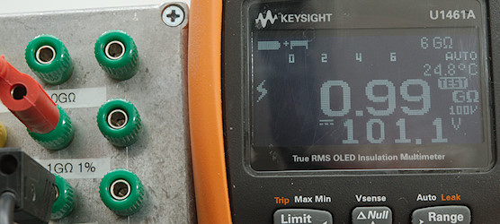
There is absolutely no problem testing the 1Gohm resistor.
When testing resistors it is important not to go above the rated voltage of the resistor, it is fairly easy with this meter.
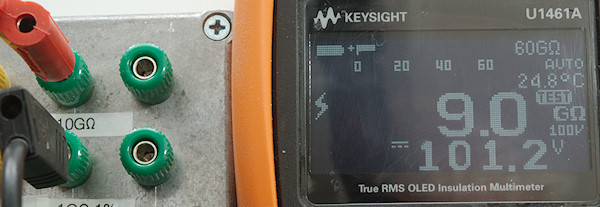
The 10Gohm resistor can also easily be measured.
Capacitors
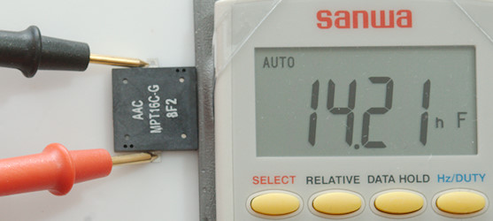
Capacitors exist in values from a few pF up to 1000’s of uF or even F for super capacitors. This means the difference between the smallest values and the largest values used is around 10 000 000 000 000 times (10pF to 100F), there can be a few zeros more or less depending on what exactly is included. A multimeter cannot cover that range, usual the low range is covered (more or less), the problems is the higher ranges. The best a multimeter can do is around 100000uF or 100mF or 0.1F (All 3 are same value), they do not handle F and some meters cannot do more than around 100uF.
Multimeters are not very precise when checking capacitors, or maybe it is better to say that some capacitors are not very precise. The value may change with temperature, frequency and voltage and some capacitors leaks current. This do not prevent multimeters from being useful to check if a capacitor is close to expected value or establish the value of an unknown/unmarked capacitor.
Multimeters only check the capacity, but especially with old electrolytic capacitors the parameter called ESR (Equivalent series resistance) is important to check. In some cases, especially with higher voltage, leakage current may also need checking, this requires another type of meter.
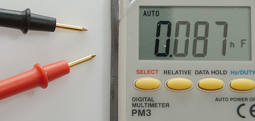
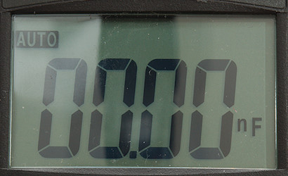
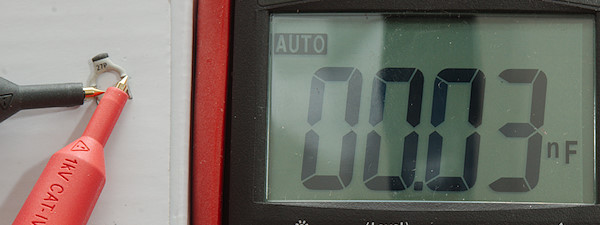
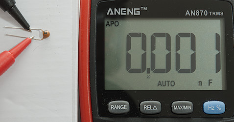
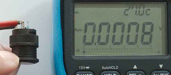
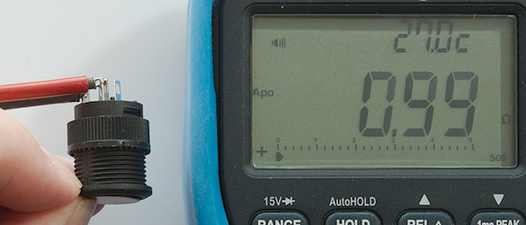
Let’s first do a test without any capacitor, this is 0.087nF or 87pF, that is not correct. Specifications for multimeters nearly always says to use the REL/NULL button in the low capacity range, let’s try.
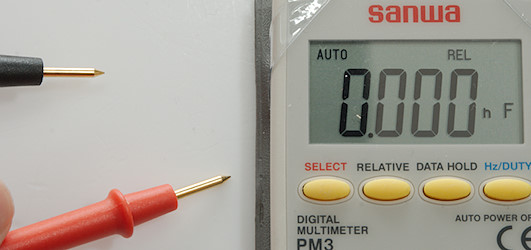
Now it shows 0 (It changes up to 0.003). This is much better.
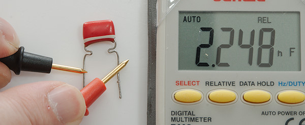
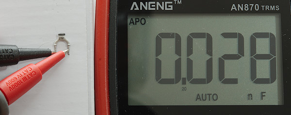
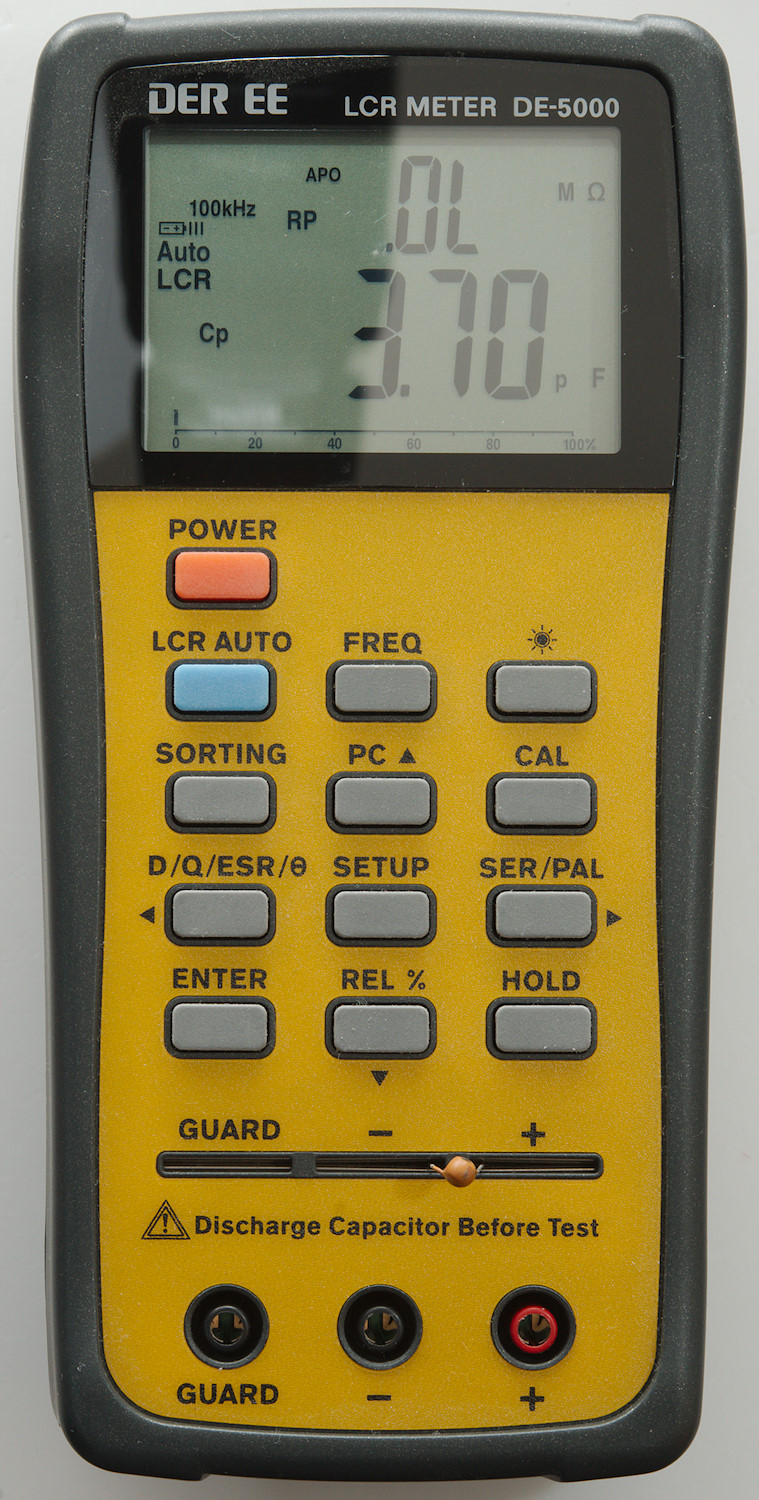
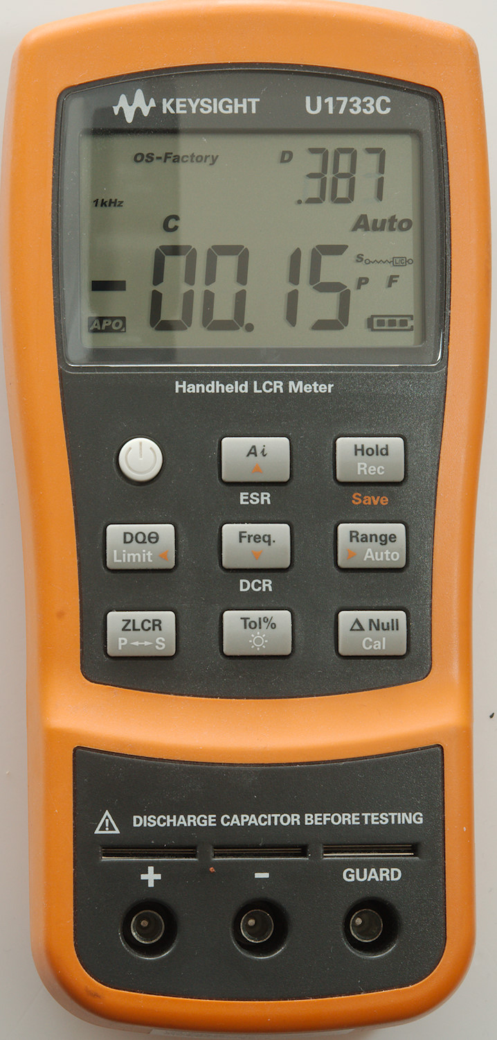
First capacitor is marked 27pF, it must be well above that?
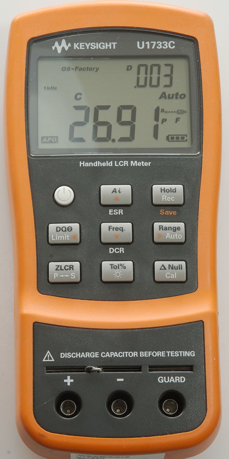
Let’s check with a real LCR meter, capacitor is in the slot just above the input terminals. It says 26.91pF, this means the error was from the multimeter, not the capacitor (In my reviews I only check down to 1nF).
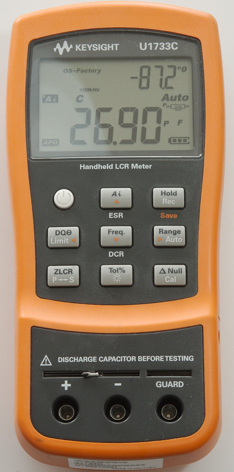
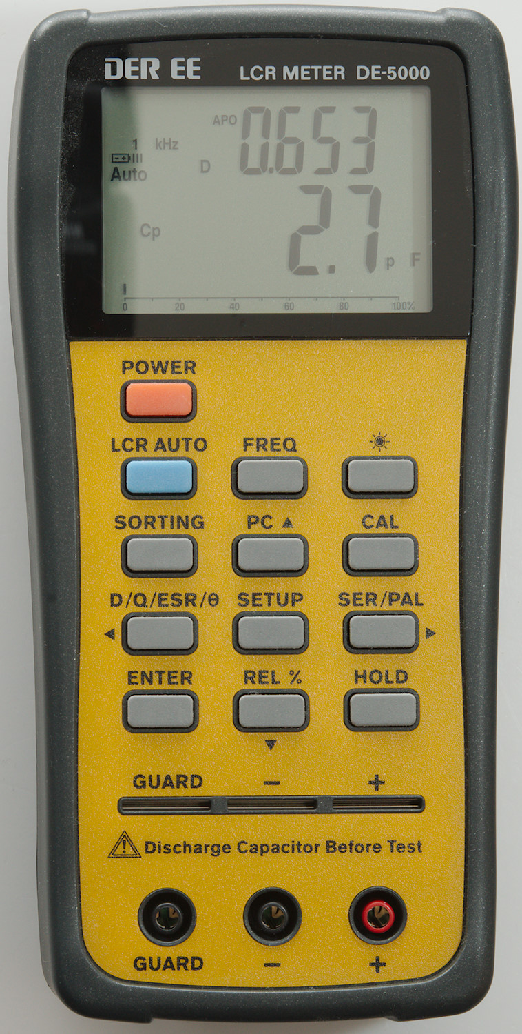
With an LCR meter I can also check at different frequencies, here I measure at 1kHz and 100kHz. This capacitor does not change with frequency.
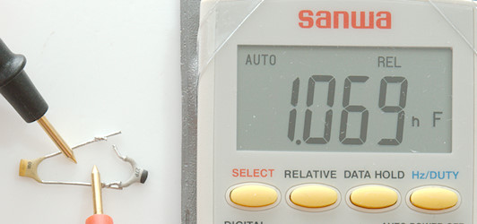
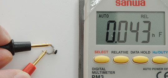
There is a way around this, first I measure a 1nF capacitor (The 27pF is NOT connected).
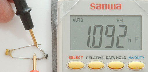
Then I put the 27pf in parallel with it and measure again. Now I can calculate the values as 1092pF-1069pF -\> 23pF, this is a much better result. This method is described in the manuals for some multimeters.
When measuring low values, the test probes will also affect the result, if the two test wires are close or not can easily affect the result with up to 50pF! To avoid that use very short test leads, twist them or be sure they do not move after using REL (This was not the problem before).
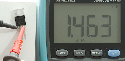
A 2.2nF works much better.
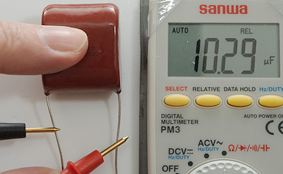
Same with a 10uF film capacitor.
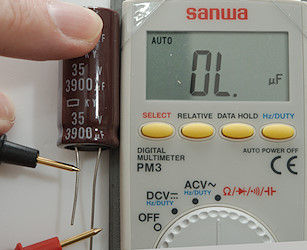
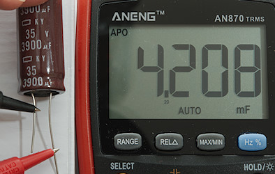
But this 3900uF capacitor is too large for the meter. It took the meter a long time to discover that.
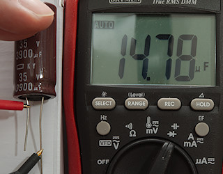
Let’s try another meter. On this meter there is one digit less in the low capacity range.
But the reading of the 27pF is fairly good (The meter took a few second to measure showing 0.01, 0.02 and then 0.03).
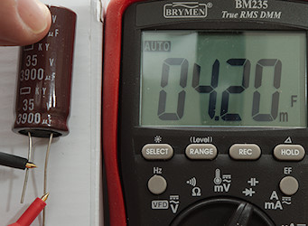
It can also measure the 3900uF. the value is showed in mF (This is normal for multimeters) and the 4.2mF is the same as 4200uF. With electrolytic capacitors the leakage current may sometimes prevent the meter from measure them.
Connecting a electrolytic capacitor with the correct polarity can be important, even though the voltage from the multimeter is low enough not damage the capacitor.
Not all meters have problems with small values, this meter handles it nicely.
It can also handle large electrolytic capacitors.
Very very small capacitor do not really work, this capacitor is marked 2.5pF and the display changed between 1pF and 2pF.
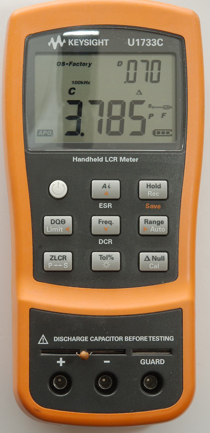
My LCR meters do not believe the 2.5pF, but both insist on 3.7pF.
Diodes
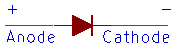
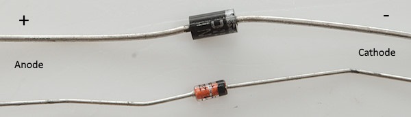
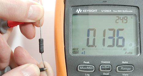
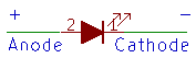
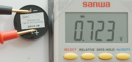
Diodes have polarity, i.e. it is important to place the red and black probes correctly. The identification on the diode is often a colored ring (Silver and black in the picture). If voltage is applied according to the + and - current will flow in the diode.
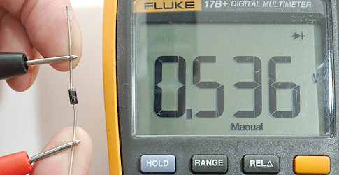
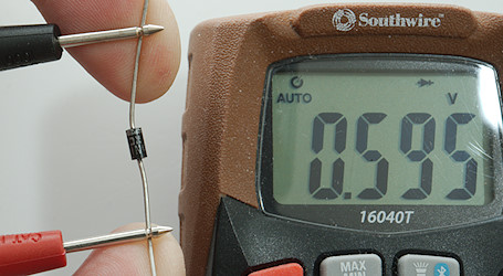
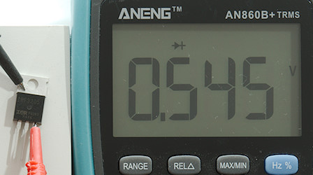
This diode (1N4007) has a 0.536 volt drop when conducting according to this meter.
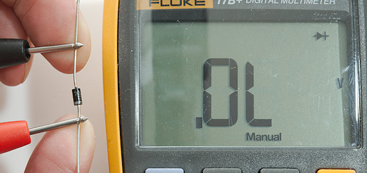
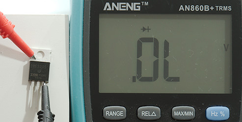
And it is blocked the other way around as it is supposed to be.
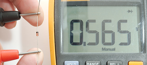
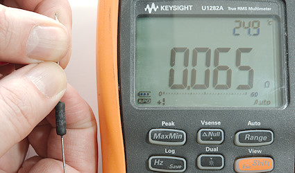
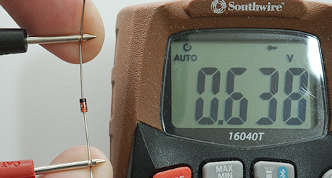
This diode (1N4148) is smaller and has a slightly higher voltage drop.
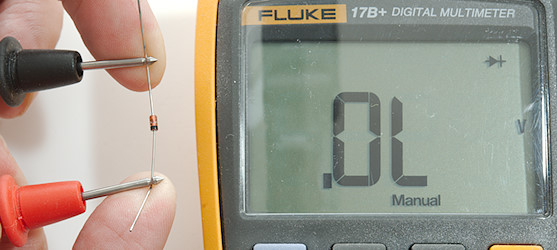
And also blocks the other way around. If the diode has 0V in any directions it is dead, OL in both directions also means a dead diode.
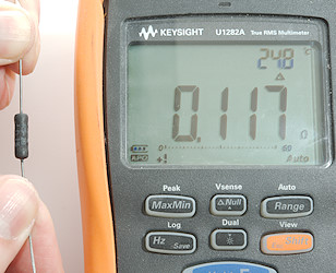
It looks very precise when we get the diode voltage with 3 digits, but with another meter I get another value.
Same with the other diode. What is correct?
The correct answer is both!
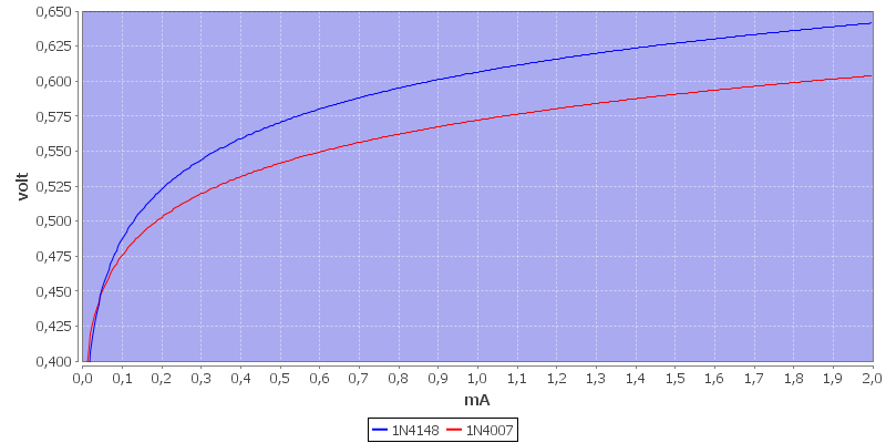
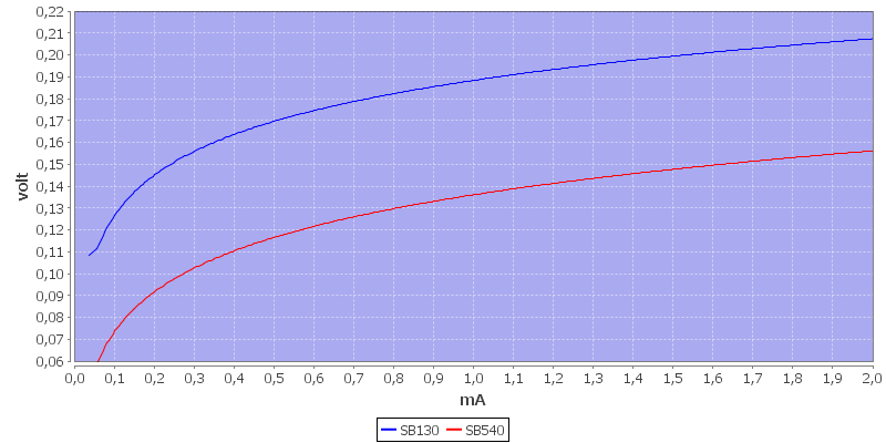
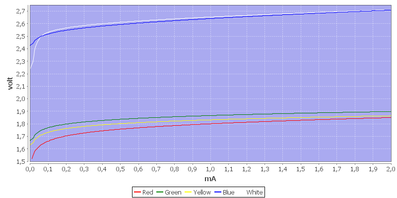
Here I did curves for voltage vs. current for the two diodes. The difference it because the two meters use different test current. For Southwire the current is around 2mA at 0.6V, Fluke is about 0.4mA.
But the precision is not completely wasted, diodes can be used as temperature sensors where the voltage drops about –2mV (–0.002V) for each degree the temperature increases, the meters has enough resolution to make a rough temperature estimate.
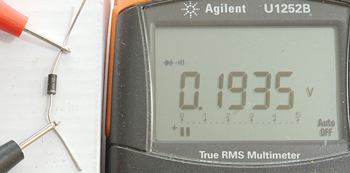
Not all diodes are around 0.6V, a type called Schottky diode has considerable lower voltage in the on direction. These diodes are often used to reduce loses in switch mode power supplies, but they are also used in other places.
The voltage across a Schottky diode is around 0.2V
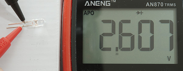
Leds
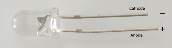
The LED uses the same symbol as a normal diode, except a few arrows are added to symbolize that it radiates something. For 3mm and 5mm leds it is usual the long pin that must be connected to plus.
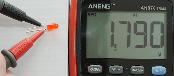
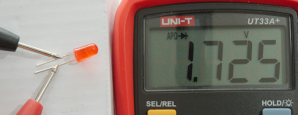
Leds are a type of diodes, but have higher voltage drop. The red one is about 1.8V. There is light in it, but due to the light used for taking photo, it cannot be seen.
Like diodes it is important to put the probes on the right way around, it is often the long pin that need the red probe, but not always.
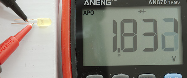
Yellow has slightly higher forward voltage drop.
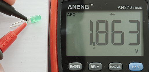
And green a tiny bit higher again.
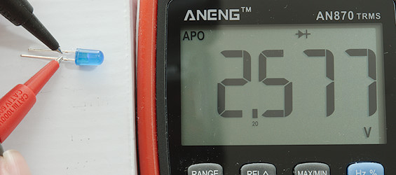
The blue led uses another technology and has much higher voltage drop.
The white led is similar to the blue led. It is a blue led, but with phosphor to convert the blue light to white light. There are also some red, green and other colors that uses phosphor leds, they will all have about this voltage.
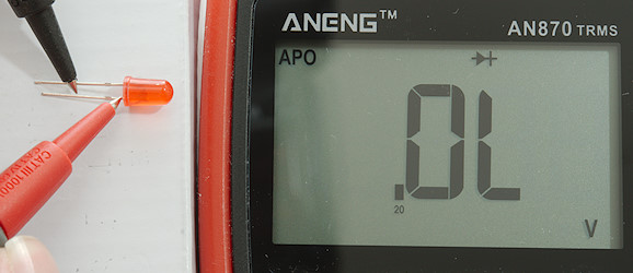
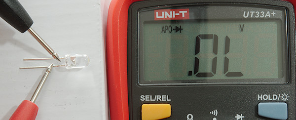
Leds blocks the other way around. If the led has 0V in any directions it is dead. The OL can be either due to the meter not supporting the led type or because the led is dead. On some meters the led might light up, even when the meter shows OL (This, of course, means the led works).
This meter uses a slightly different test current and the voltage is different (See curve below).
But what is this, is my white led defective? The answer is no, but the meter cannot check white and blue leds. Multimeters come in 3 types for diode testing:
-
With 1V diode testing, can only test normal diodes.
-
With 2V diode testing, can test normal diodes and red/yellow/green leds.
-
With 3V diode testing, can test all single leds.
In led bulbs for mains there are often used more leds inside each chip, i.e. they cannot be tested with a normal multimeter.
The forward voltage depends on color and current, this means different meters will show different forward voltage.
This voltage depends mostly on the led color, not as much on package like SMD, 3mm, 5mm or power (There will be a small variation depending on size of led).
Testing in circuit with power off is sometimes possible. The result must not show 0 volt or a voltage above the expected forward voltage. If the forward voltage is lower than expected, it may be the circuit that is doing it.
Transistors
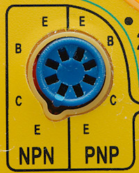
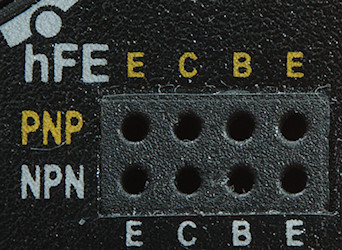
Many cheap multimeters includes a build in transistor tester, it is marked “hFE” on the range switch, that is the letters used for gain in a transistor. This tester is fairly useless for a couple of reasons:
-
Transistors exist in many different packages, only one with thin leads are supported, neither SMD or POWER packages (Like TO220) are supported.
-
Today many transistors are MOSFET, the tester only support BJT (Bipolar junction transistor) types.
-
The tester only works for smooth pins, transistors that have been soldered in a circuit can be difficult to test.
-
The test is very simple and can easily be fooled.
It do also compromise the safety of the meter (Maybe not as much on a cheap meter, they are often low safety anyway). Safety distance from metal part inside meter to where you can put your finger is fairly low on a transistor tester socket and if you have left a transistor in the socket it is non-existent (The inside of a multimeter can be at high voltage when measuring high voltage).
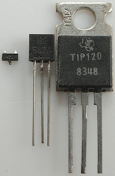
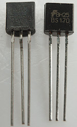
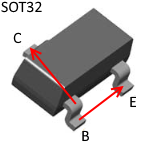
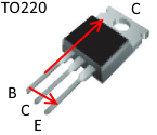
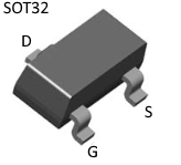
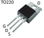
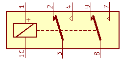
Here are 3 of the transistor sizes: SMD small signal (SOT23), leaded small signal (TO92) and power (TO220) and the two common transistor types: BJT and MOSFET, as I said above only one of these are supported.
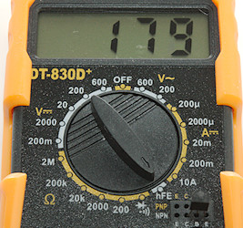
A transistor of the right type in the socket and the range switch in the hFE position, then I can see the gain (at a unspecified current). This transistor obvious work or do it?
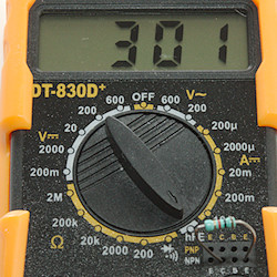
What about a resistor? This resistor has a gain of 300, i.e. it is better than the transistor to amplify current? This is, of course, wrong. The problem is that the tester only measures current, the base current is defined with a resistor. Anything that passes current from C to E connection will be shown as a working transistor with some gain, even a resistor or a damaged transistor.
Transistors again, BJT types
When not using a transistor tester, how can a transistor then be tested?
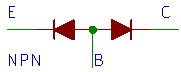
It is not that difficult, the above schematic shows how a transistor will measure. It is basically two diodes and can be tested with any multimeter that has a diode test mode. There is only one problem and that is knowing what pin is what.
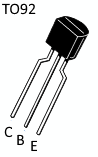
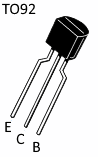
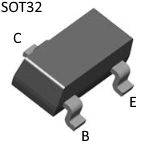
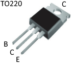
Here is some of the most common pin-outs. In SMD a package very similar to TO220 is often used, it has the same pin-out.
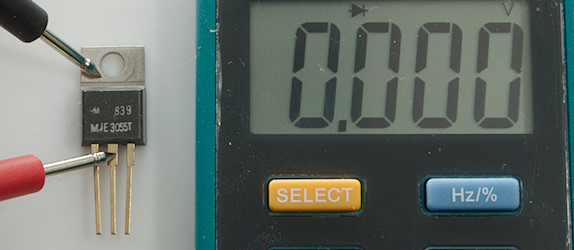
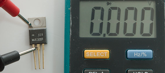
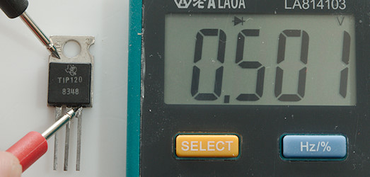
For demonstration I use a transistor in TO220 package, it is large and easier to take pictures of.
The centre pin is the same as the tab on the TO220 package, this is often used in circuits and can also make it easier to measure.
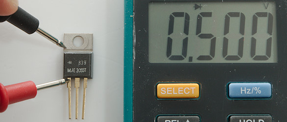
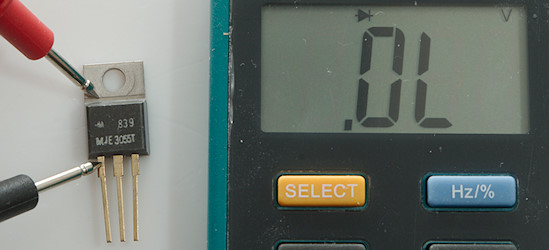
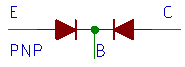
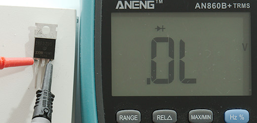
First test is the B to C path, with the red pin on B the diode has a forward voltage and will conduct, the other way around the diode is blocked. This is a NPN transistor, a PNP would be the opposite way as can be seen on the diode symbols at the start.
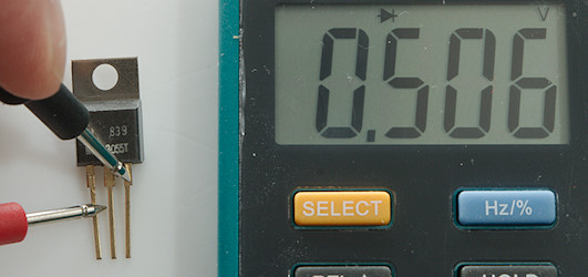
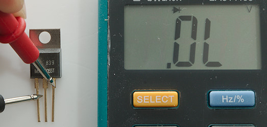
The E to B path is tested the same way and gives the same result.
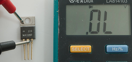
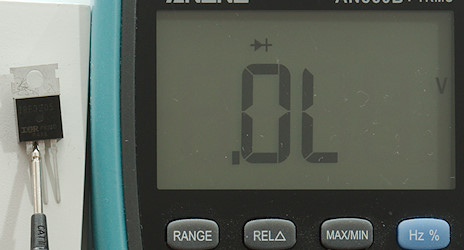
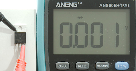
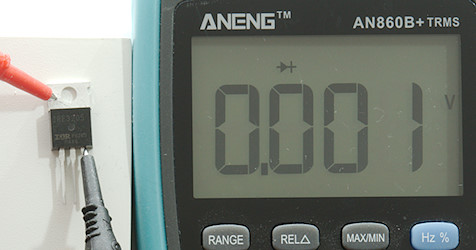
E to C path is blocked both ways.
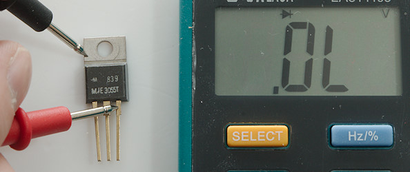
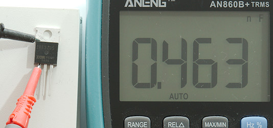
But things are not always that easy, this transistor shows a diode from E to C, is something wrong?
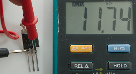
There is also a resistor (Note meter is in ohm) from B to E, what is going on?
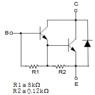
Here is the schematic of the transistor, it is a Darlington transistor (Two transistor connected in this way) with some resistors and a diode. The resistor is not exactly the same as the schematic shows, but close enough.
With some meters you have to be careful when measuring the resistor, it is in parallel with a diode and if the ohm measure voltage is high enough to turn the diode on, the value will be wrong. Solution: Swap pins and measure the other way around or manually select a higher range (It will usual mean lower test voltage for the same resistor)
The diode tests will usual also work in-circuit with power off, except the blocked paths may not show OL, but instead a value. If they are close to 0, something is wrong and you probably need a new transistor.
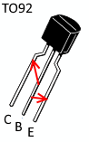
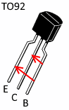
Cheat sheet for NPN transistors, place the red probe at the back of the arrow and black at the point of the arrow to measure a diode drop. For PNP it is the opposite way around.
Transistors again, MOSFET types

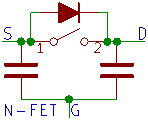

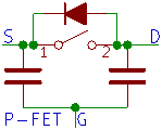
Here is the symbol for a N-channel and P-channel MOSFET and how it looks when measuring on it. What can usual be checked is that the diode is there and the switch is open. The switch will only be open if the G voltage is 0, with enough positive voltage (For N-channel) on G the switch will close.
This MOSFET is called a enhancement mode MOSFET transistor, it will turn on when a voltage is applied to the gate, how much voltage depends on actual type. There exist another FET type called depletion mode, that is on until negative voltage is applied. This type is very rare as MOSFET, but is sometimes used in JFET versions (A JFET replaces the capacitor with a diode in the non-conductive direction), these are also fairly rare.
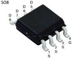
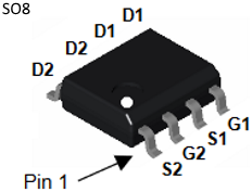
Some common SMD versions. The first SO8 is usual easy to see on the circuit board, because most pins are connected. The second SO8 is two transistors in one package.

The most common leaded versions.
The centre pin and the tab is connected as usual for TO220 packages.
The gate is not connected to anything, I could connect test probes either way and the result would be the same.
G is a capacitor to S and D.
Before testing, be sure the gate is discharged, this is done by shorting G to either S or D.
Correctly G must be shorted to S, but because there will be a short between S and D if there is voltage on the gate capacitor, shorting to D will also work.
The diode is working.
And the MOSFET is blocked the other way around.
A little trick, if it works depend on the diode test voltage (3V or more is best) and the actual MOSFET.
I am measuring between S and G with the positive pin on G (For a N-Channel MOSFET), this means I am charging the G capacitor and turning the MOSFET on (If I have enough voltage in diode mode).
The mosfet is turned on.
MOSFET can often be measured in-circuit with power off, there the gate will usual be discharged, i.e. the diode can be checked and there must not be around zero ohm between S and D.
Other
The multimeter can be used to test many other components and parts, here a few examples.
Bridge rectifier
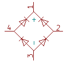
A bridge rectifier is 4 diodes and each diode can be tested.
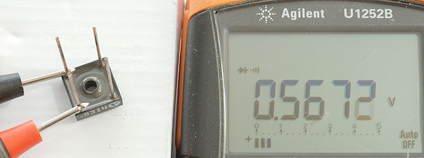
Here I am testing one of the diodes.
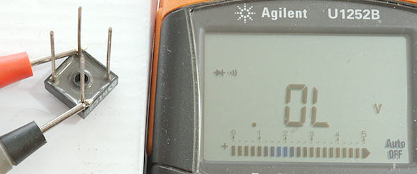
Testing from + to - is also possible, here with the red probe on +.
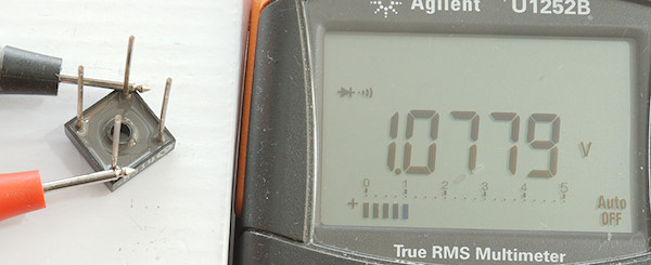
Moving the red probe to - show two diode voltage drops (Beware, not all multimeters can handle that).
Relay
A relay is a coil (Measures as a resistor) and some contacts (The pin numbering on the relay do not match the one I test below).
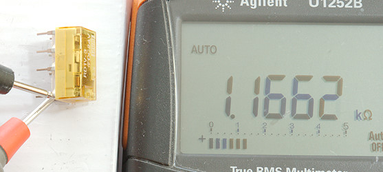
I can check that the coil have a non-zero resistance.
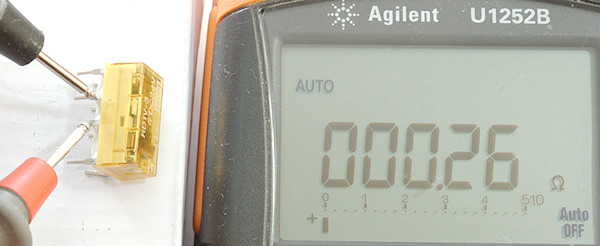
And I can check the normally closed (NC) contacts. The normally open (NO) contacts will read OL or the resistance of my fingers. Continuity can be used for this test.
The relay test is not complete, because the NO contacts is not tested in closed condition, this would require some external power to activate the relay.
Passive buzzer
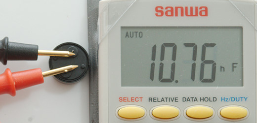
A buzzer is a capacitor and will measure as such, it may also be possible to hear a tone from it, but that depends on the meter.
Another buzzer.
Active buzzer
A active buzzer marked with + and -, here I use diode mode and the buzzer will make a weak sound.
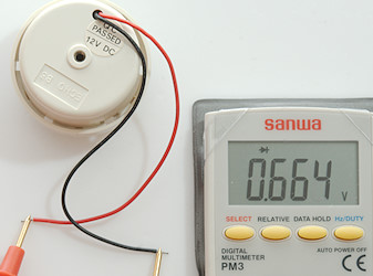
Even this 12V buzzer will sound with the diode voltage.
Switch
With a switch it can be useful to check if it is momentary or toggle, connections of the pins, especially if it has a indicator light and for old switches also if it even works.
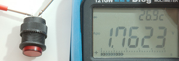
The indicator light, it is a red led. A incandescent bulb must will show a value higher than a direct short, in ohms it may be from a few ohms to a few hundred ohms.
I can also the rest of the switch in diode mode, 0V means a connection.
Continuity is faster, because I do not need to look at the display, I can just listen for the beep.
What to look for in a multimeter
For component testing you have to look for these parameters:
-
Cables/connections: A fast continuity mode.
-
Low ohms, what resolution do the meter have in the lowest ohm range, the best meters have 0.001ohm
-
High ohms, what is the maximum value that can be measured, usual it is between 10Mohm and 100Mohm.
-
Very high ohms, some meters have a nS range (or a high ohm range), that can measure much higher resistance or just get an insulation tester/meter (Most insulation testers are not general purpose meters).
-
Capacity low values: What is the resolution in the lowest capacity range, some meters has 0.01nF, other 0.001nF, you also want a REL or NULL button.
-
Capacity high values: How high do the meter go, best is two digit mF values, also check how fast it is at these values.
-
Diodes: If diode and continuity is same range, the display may show ohms and not volt.
-
Leds: How high do the diode test voltage go, for white leds a meter that can display up to 3.000 volt is best.
-
Transistors: As long as the meter has a diode test, you are fine, test voltage do not matter
Alternative ways to test components
There are alternative devices to test components, some more precise, some more convenient, some more universal, some cheaper. Common for all dedicated component testers is very basic input protection, they are not supposed to be plugged into mains voltage like a multimeter and do simply not need much protection (Be careful with charged capacitors around component testers, they cannot handle them).
The cheapest type is a circuit board with a microprocessor and a display and not much else, it can test many component types and value.
I have tested a few of them:
Component tester Multifunction Tester T1
Component tester MK-168
Component tester Fish8840
One brand have made their own series of component testers, they are not as cheap or universal as the above, but higher quality:
Semiconductor tester Peak DCA75
LCR tester Peak LCR45
And then there is LCR meters, they use AC with selectable frequency to test resistors, capacitors and inductors:
Bench meter versions of these meters have better precision and may also be able to apply DC voltage/current to measure at the correct operating parameters.
Notes
I show a different way to do low ohmic measurement here Measurement on Flashlight This method can be used with simpler power supplies, but requires a power resistor and more calculations.