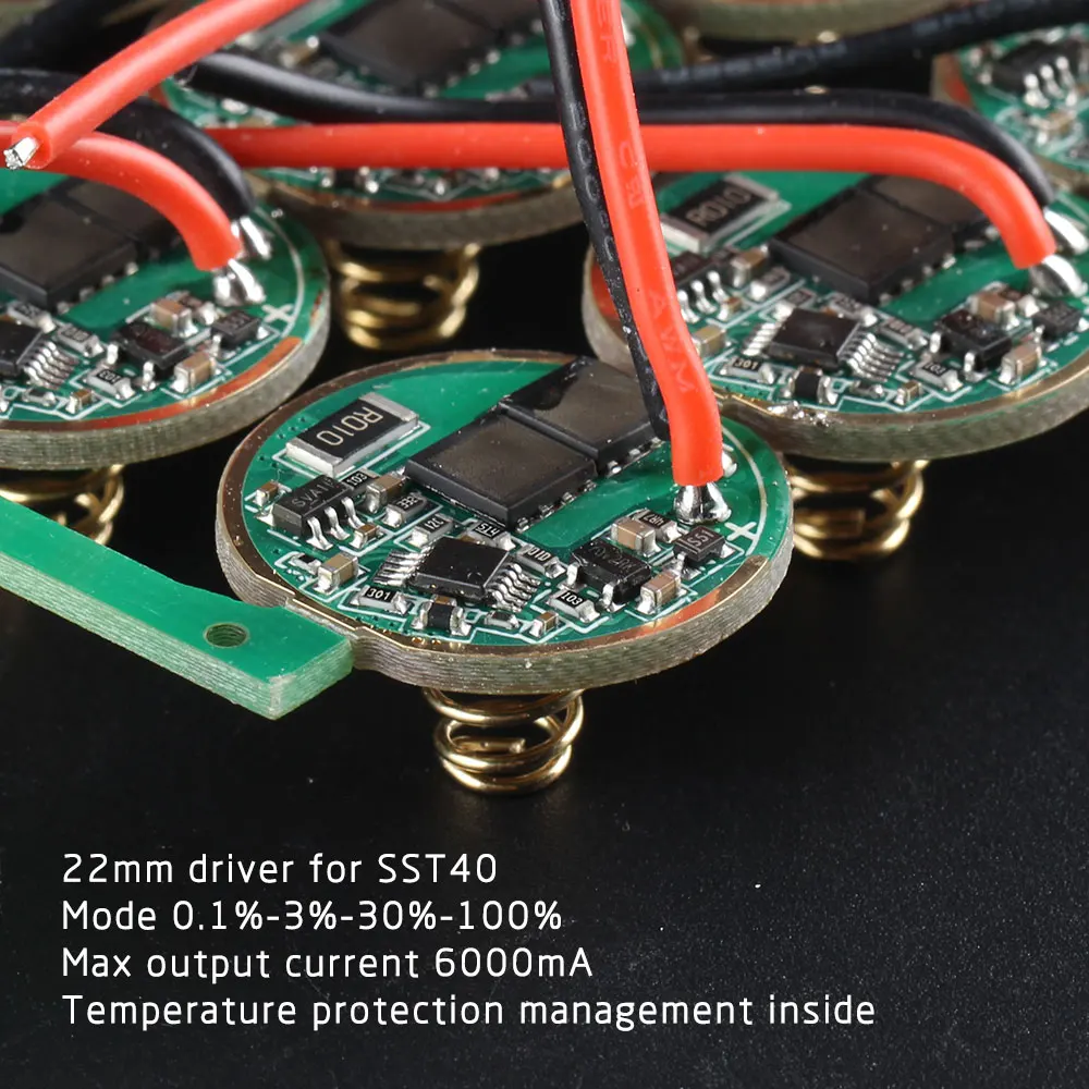
The missing contact ring track or ground ring track is that in the driver's front or upper side, at least as far as I know or understand these things. The back or bottom side is where the spring dwells.
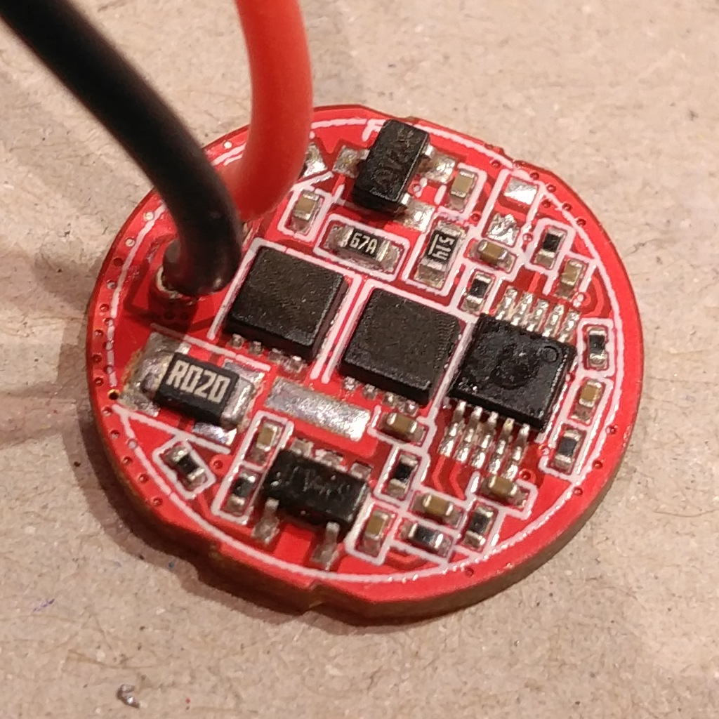
I have a couple drivers and as you can see in my picture, I removed the NTC thermistors.
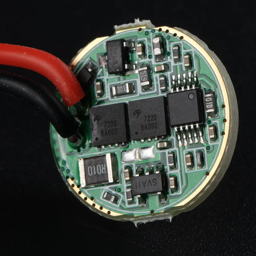
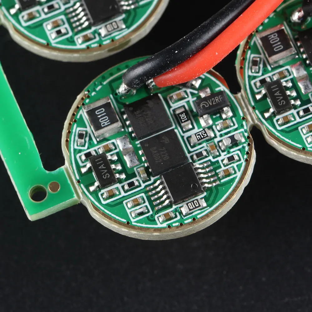
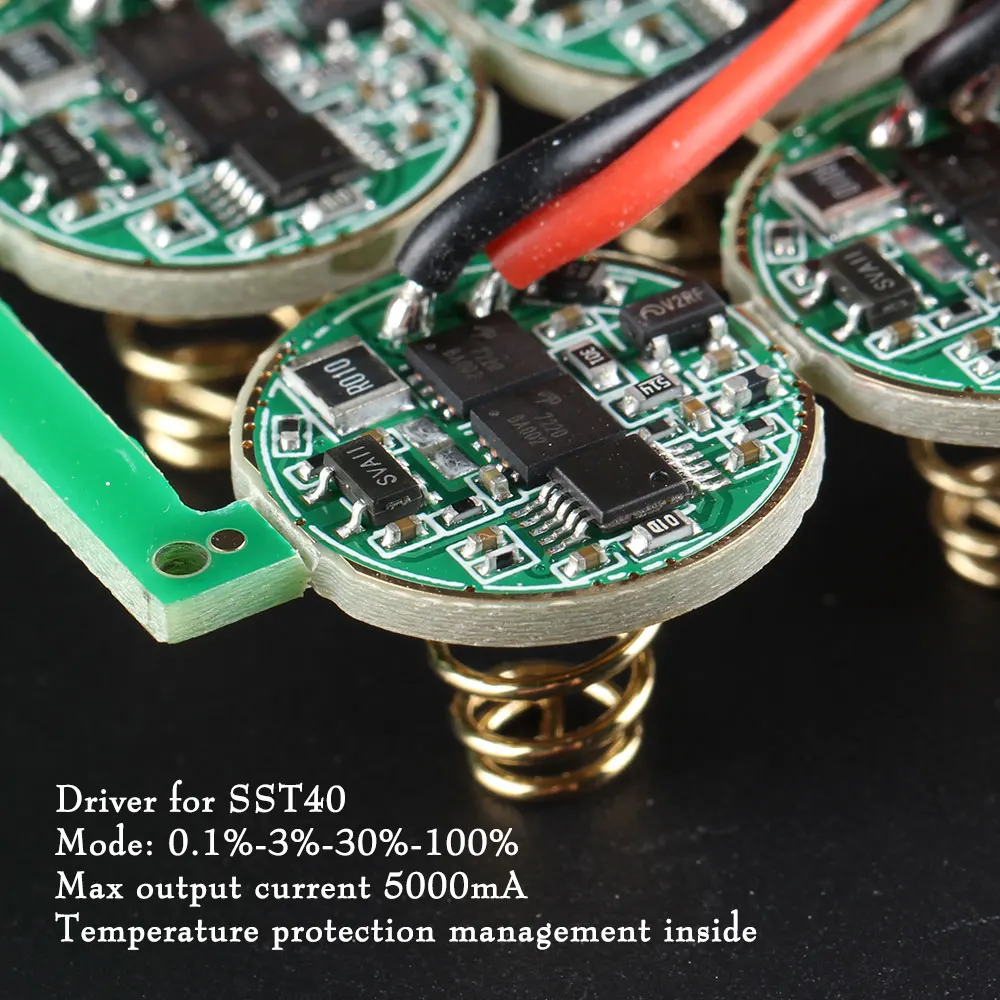
Notice the presence of an outer ground ring track in the green solder masked 4-mode drivers.
Without temperature protection I can only rely on good thermal transfer for my driver to work properly. But these drivers don't have upper or component side ground ring so, unless I am missing something, their life is gonna be rather short because of overheating. :???:
I am feeling rather uncomfortable at this right now.
Still, I have to come back and pinpoint this. My M2 build cannot work this way. The retaining ring has a sloped inner surface ring on the side which is in contact with the driver, and a small flat outer surface ring (which makes no contact with the driver unless I were to forcefully slip it). As it is, I can only make it work reliably by soldering the retaining ring to the driver. And I defitively don't want to resort to that!
Will wait for Simon to see what he has to say. I think I'll have to order a set of 4-mode drivers (drivers with a working, solder mask free outer ground ring in the component side), which even if I get some refund is going to be :(( another long wait.
Is it possible to use by flip’n the retaining ring over, file 2 slots in it for tightening with needle nose pliers. I have wire gauge drills that in this case I would just drill thru the holes in the retaining ring, deburr and use the other side of the ring…
I tried this with my C8 when I got the new “biscotti” driver. It didn’t work with the retainer the right side, so I flipped it and got the light to work for a few seconds then it killed the led and smoked the driver…something wasn’t happy with the setup! Maybe a short? I never figured out what happened.
I ordered 4 drivers, they have not arrived yet.
I’m alarmed by the conclusions of some colleagues, but let's not panic ahead of time. I would like to see Mr. Simon's answer. If a persistent problem is discovered, a solution will be found, I am sure. In any case, you are in a better situation than me, you at least understand the reasons, and how to fix it)
Hum, I know Simon will have an answer or a solution for this situation for sure!
But, the driver structure seems, indeed, strange.
Let’s try going bakwards: was that driver - with the same structure (meaning, no contact on the upper side) - originally used in any flashlight “ready to buy” from Simon?
Or was it made as it is for us moddersn, to try to fit it in “any” flashlight taking a 17mm driver?
Could it be someting related to those adapter rings that Simon sells to make smaller diameter drivers fit flashlights with larger driver diameter holes? https://www.aliexpress.com/item/33023608406.html
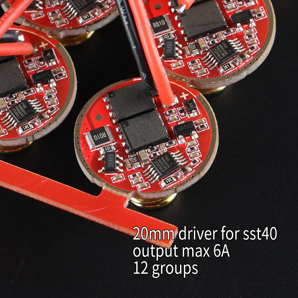
EDIT: I am not sure if my assumption is correct, but these adapters, are sold for 2 specific lights (M21A and S21A) that use the SST40 Leds, the one for which this driver is suitable/designed for.
As the adpaters have an upper ring, that will make contact both with the lower ring (and the bottom of the driver), and the pill, maybe they can replace that contact edge of the driver.
Hence, it seems to me that this may be the reason why these drivers have that design, to be used in those 2 specific flashlights, with those adapters!
But I may be wrong
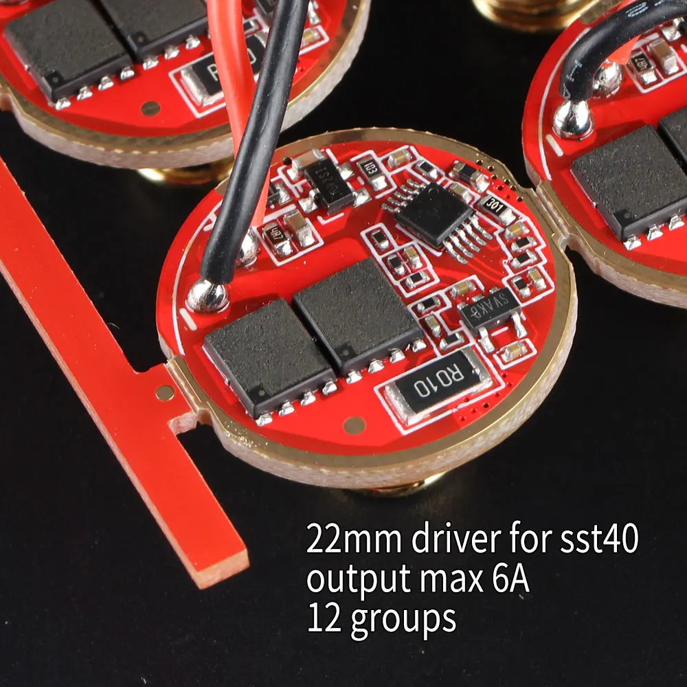
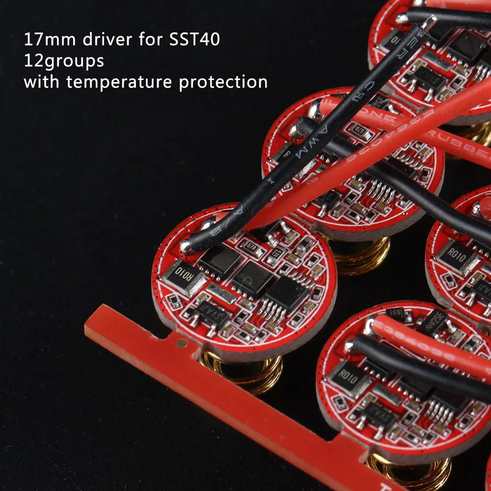
I think this is a problem related to the driver manufacturer. If you look at the driver advertisement pictures, the only driver which has a solder mask covered upper ground ring track is the ∅17mm version with 12 groups firmware:
The 17mm was the one I got that was missing the contact ring. It died in my C8 with the retaining ring. I have another one on order…been in limbo for over a month over the Pacific somewhere. I hope Sim9n has a solution.
I second that - I've done scraping off of solder masks many times. I use an exacto style knife with a curved blade. Did a lot of that on Q8 battery/spring boards but also on many drivers. After you scrape and you might not be sure good contact is made, then add some solder - it can easily be sanded or filed down to the proper height. Again, did this several times.
Sorry, because of some manufacturer’s consideration, it made a little change to the driver, and it will be changed back in the future.
Another cause of poor contact is the bevel on the retaining ring.
I guess you refer to the solder masked top side :???: ground ring in the ∅17mm 12 groups drivers. Is any other driver size or version affected?
This is an unpleasant mishap. I'd give the manufacturer a good pull in his/her ears. Sirstinky already reports a nasty issue here, and I am sure others must be experiencing some problems even if they are not aware at first. The solder mask reduces the heat transfer from the driver to the flashlight body, this may be causing earlier than expected thermal throttling in user flashlights (there are reports already, although don't really know if this is playing a role).
Hope this is fixed as soon as possible.
P.S.: any idea of the actual impact of the solder mask in heat transfer?