Post #1896 for reference... Continued here
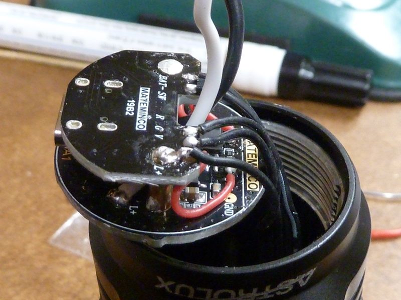
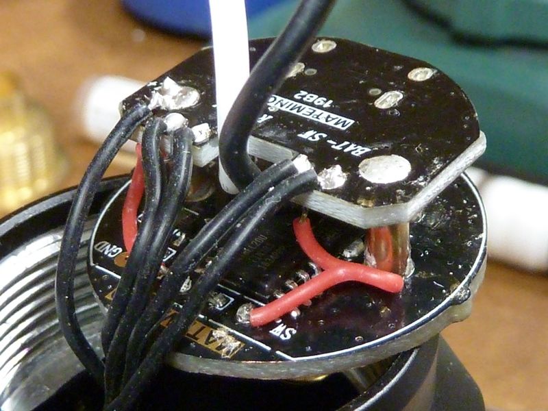
The driver
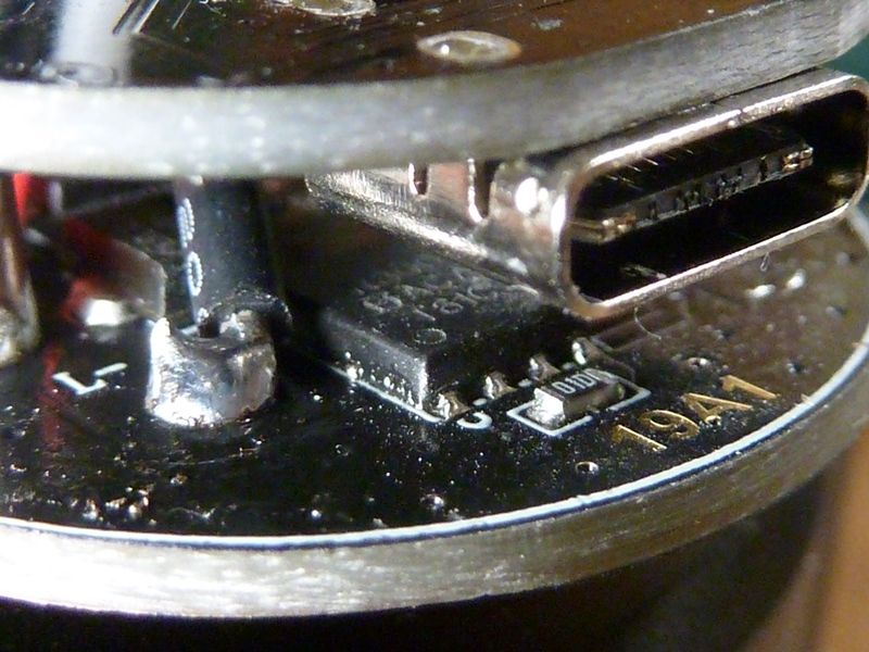
It's got a 5 wire harness going to the switch (Batt+, Batt-, Red, Grn, Switch) - no idea why Batt+ is needed. 2 boards - the contact board id the LED driver, and the piggyback board is the USB-C charging:
The ATTtiny85 running NarsilM v1.3:
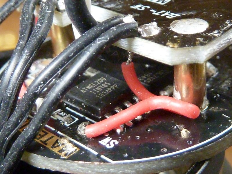
The fake SIR800DP. Yes - these are not the real thing but should work pretty well:
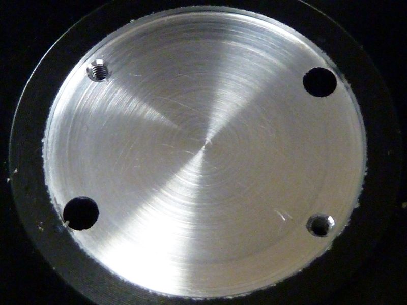
The MCPCB
after polishing, best I could measure was it went from 1.60 mm down to 1.58 mm. Started at 320 GRIT, all the way to 2500 GRIT:
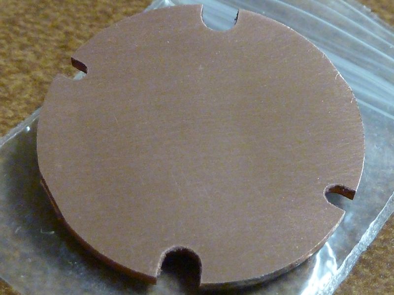
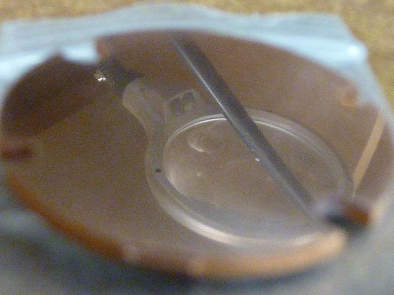
Reflection of a magnifier. Yes, it's quite polished now:
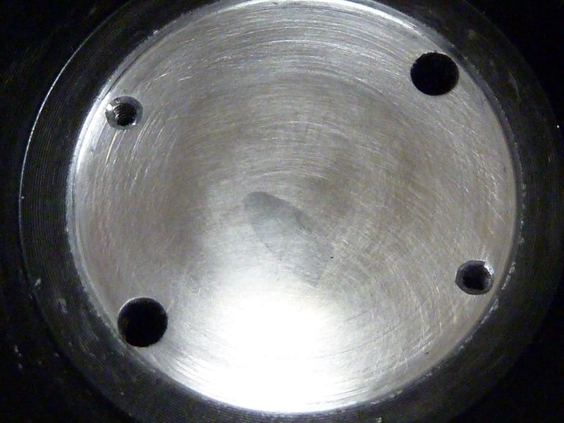
The shelf with machining marks, but after I beveled out the screw holes -- looks nice now, used a simple larger drill bit, works wonders:
After polishing to 2000 GRIT:
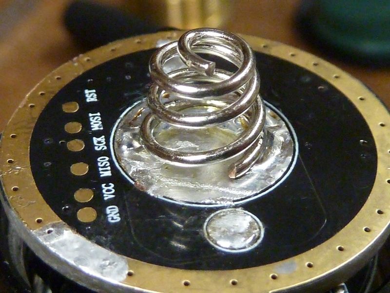
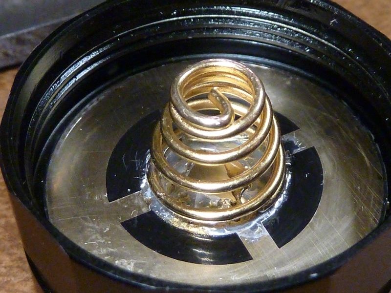
Springs
Replaced the stock double springs with the Blue Be/Cu large from batch #1, cut off 1 1/2 rings off the bottom. I want to get lower compression. Batch #2 springs are too stiff for this usage:
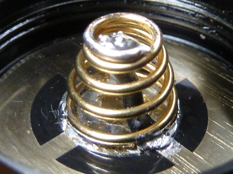
20 AWG bypass:
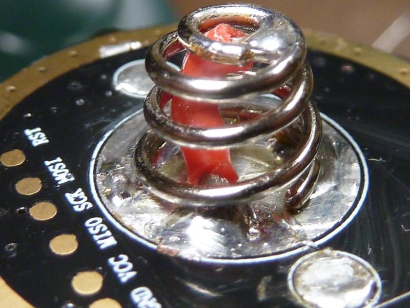
Tail spring with the inner removed, stock outer, 20 AWG bypass:
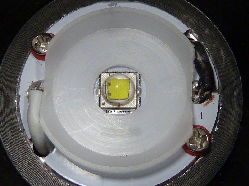
Sanded down centering piece. Could not get the LED centered - the wires interfered:

All done:

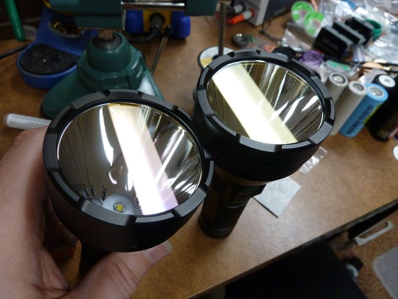
2nd on left, 1st on right. See the purple tint on the left one and yellow on right? It was hard to catch in a pic but much easier to see in real life. Weird they changed the glass:
Full FT03 photo album: https://s1054.photobucket.com/user/TomE2012/library/Break%20Downs/Astrolux%20FT03?page=1