I’ve got new supplies and tools in hand, but have not yet done anything with them. I’ll get motivated soon.
In the meantime I just noticed that this driver also uses the QX5241a: 9A 3-Mode 5.5-12V Circuit board. HKJ wasn’t super impressed with the efficiency, but hopefully better component selection will keep us around 80%. RMM comments that most XM-L2’s seem to die around 4.15v over here (post #110), so we can see from HKJ’s scope traces that depending on the input voltage this thing would totally zap XM-L2’s. HKJ didn’t specifically mention the input voltages, only that the two traces were at different voltages.
EDIT: I forgot to mention that those scope traces (the pictures with green lines that look like wiggly square waves) look exactly like what I’ve been seeing.
Thanks VOB, I’ve been taking a break from FL projects and focusing on other things. I expect the 20mm stuff will be forthcoming as soon as I get back to this, then we’ll re-attack 17mm! The layout issues shouldn’t have much affect on component selection - therefore I expect 4A to be a non-issue. Those could be my famous last words though ;-).
Cleaned off my work area. Realized that the only thing I’m really short on is PCBs. I’ve got one 20mm blank left, so that’s what I’ll start with. After that it’s recycling the ones I had problems with.
… crap, now I gotta remember what all these parts are for and where they go!
Turns out that after all this time, these are still the right parts! ;~~)
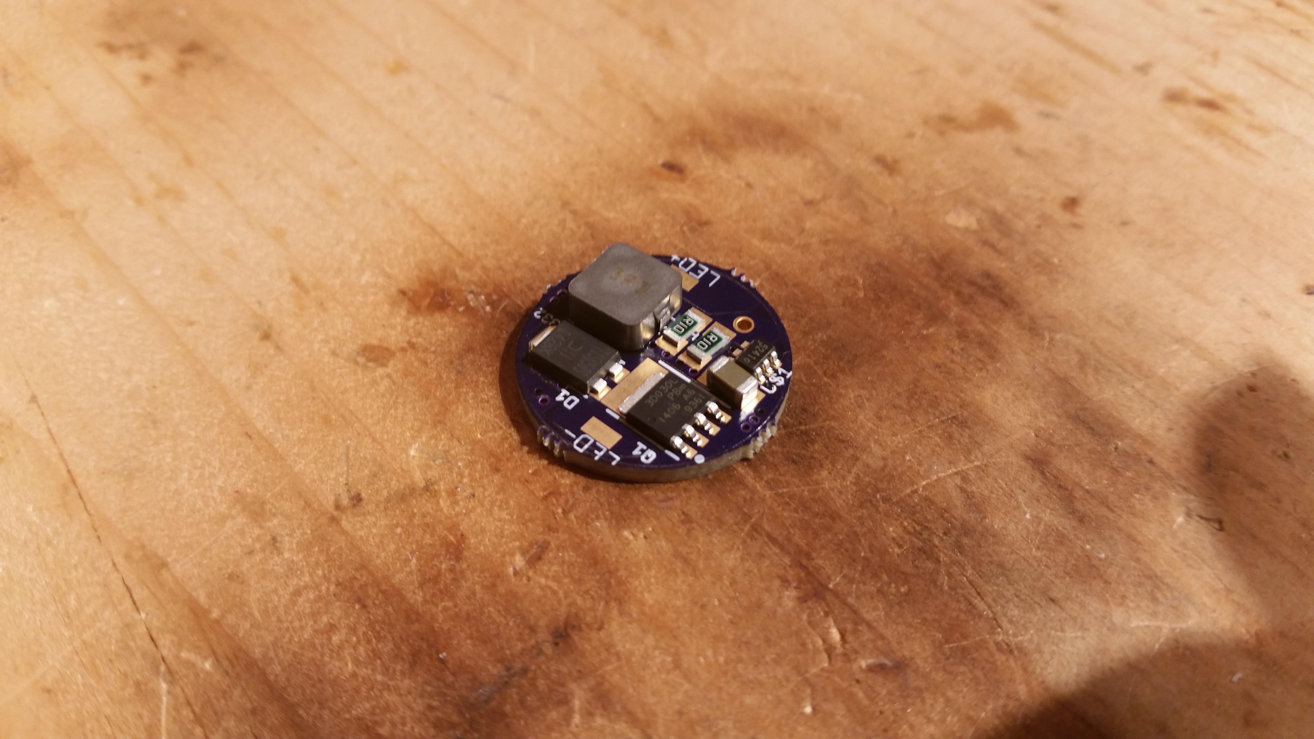
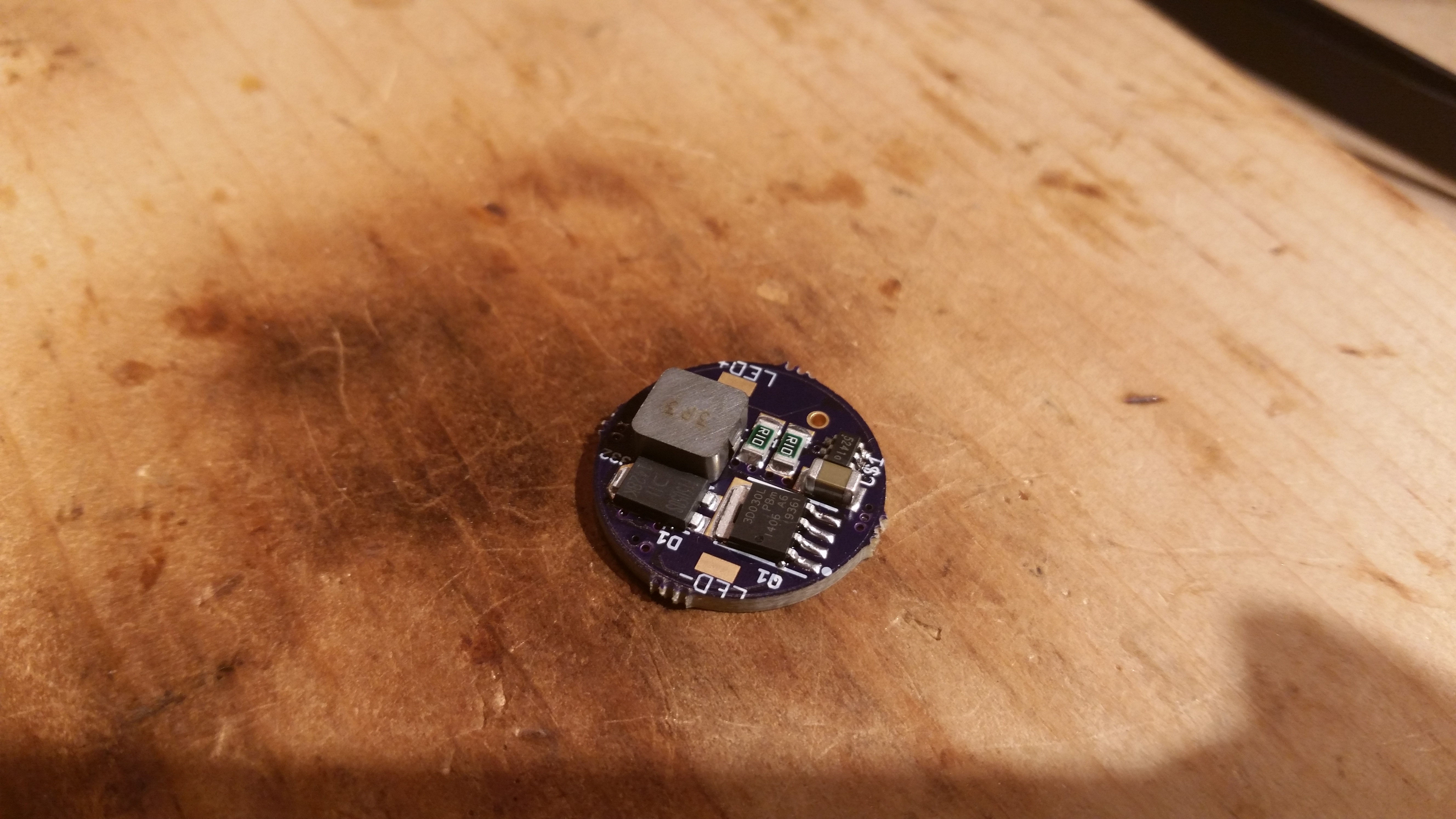
I sat down and checked my numbers, for 4A I needed two R100’s. I picked out enough of each component and laid it out on the driver to make sure I had everything, then went back and checked on the computer since I didn’t put an orientation mark on the board for the QX5241. I put everything in my little parts bowl, squoze out about the right amount of solder paste onto the appropriate pads, then placed everything for the top side of the board. I reflowed using my 1500W heat gun on the High/950° setting, let it cool, then flipped it over and installed both 0805 caps by hand, then a jumper to pull the DIM pin high since I wasn’t installing the Attiny13A. I hooked it up to a PSU at 10v / 3A and it worked, drawing approximately 1.54A and outputting just under 4A to the LED.
Next I’m going to ignore the urge to fiddle with the buck section and jump straight to installing an MCU.
Microa has experience with the QX5241 from past efforts and he did mention something about it’s internal LDO PSU not being up to snuff once Vin (battery voltage) was high enough. That’s what the MCU runs off of in this design. I’m pretty sure that the buck section will be fine with what you want to do. Powering the MCU is the only dicey part based on what Microa was saying. We’ll have to see about it!
Yes, but I will not be confident in how accurate they are. The QX5241 is known to have pretty nasty output and there seems to be some trickyness with measurements.
IIRC I’ve compared the readings from my crappy PSU and my short-thick-lead-modded HF DMM and feel confident that the voltage and current readings they provide are accurate.
But when I hookup a DMM to measure output voltage, current falls immediately. Also it seems that something bad is happening with the buck controller, because the PSU starts indicating CC with a flickering CC light - meaning there are input spikes from the buck driver.
My new ’scope will do measurements and doesn’t seem to make the buck driver wig out, but output current does still fall around 0.1A or a little less when I have the ’scope hooked up.
Here’s what I see with a “hot” test bench (heatsink was around 40-50°+):
Vin = 10v
Iin = 1.5A
Vout AVG = 3.43v
Vout RMS = 3.8v
Iout = 3.52A
Without the HF DMM in place RMS voltage is very close to AVG voltage.
I don’t think we are getting true average current from the HF DMM, so I’m not sure how accurate the efficiency calculation can be.
It seems that efficiency may be beyond >80% at 3.5A-4A output. I think it’s hard to draw a lot more from that data.
It’s also worth noting that the scope sees super high voltage spikes. I clearly see full 10v spikes. The XM-L2 LED survives. Maybe this is a sign that the L value of my inductor is much too low for this controller to deal with.
As a sanity check I put my “new DRY” driver back together and tested that. It doesn’t get along with my PSU super-well in “high” modes, but max output voltage was not equal to input voltage. More like 5.4v.
Next I’ll swap the higher value inductor from that driver over onto one of my 20mm ones.
Maximum output voltage behaves properly with the larger inductor in place. Also with the larger inductor in place I noticed an operating frequency just shy of 1Mhz. I didn’t think to check that when I had the smaller inductor installed.
I think it’s fair to say that the 3.3uH inductor is just too small for the QX5241, regardless of one of the datasheets claiming 2Mhz operation. Depending on your usage scenario of course. That’s a big factor… we might have to do some charts!
I put two of the Bourns SRP7030-3R3FM inductors in series and that seems to keep peak voltage down to 6.4v (from 10v with only one) on 10v input.
Also it looks like I need to learn how to properly use that freq counter. I can get it to show a variety of things, so instead I counted myself. It’s 4.5 divisions at 1uS/div. So it seems like “High” with this driver and the two inductors in series is operating at ~220Khz.
It is most important for things like transformers. If you hook two windings in series you will get either the sum or difference in the voltages of each winding depending upon the polarity (phase) of the windings. If you hook windings in parallel you get either the sum of the the currents… or smoke.
With just inductors, you can get a similar effect if the inductor’s magnetic fields can interact.