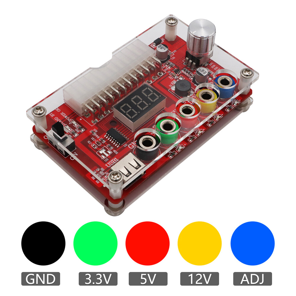
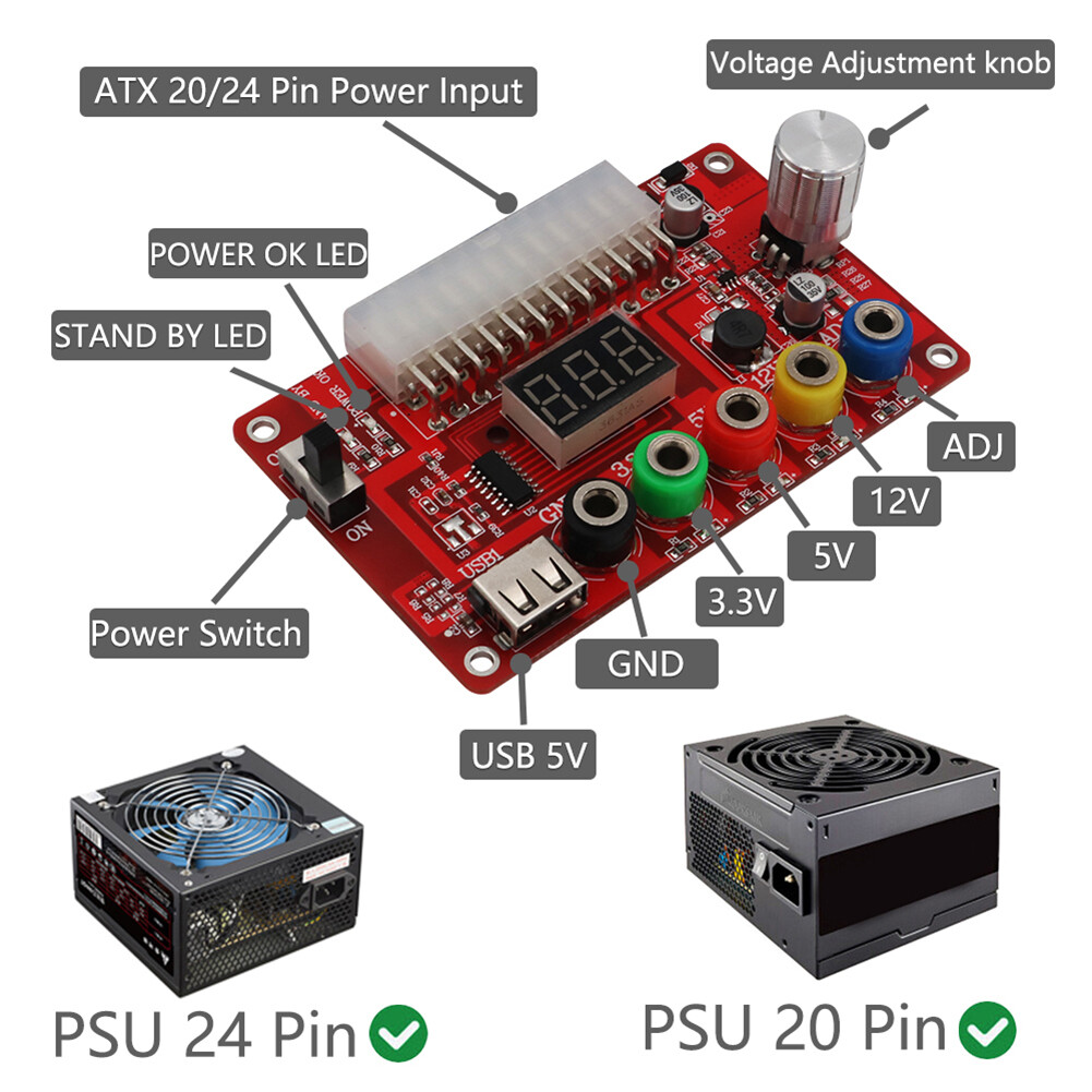
24/20-Pin ATX DC Power Supply Breakout Board Module Clear Acrylic Case Kit
So, I wanted a variable power supply, just a simple one to test/power the odd project. I tried to get help from RD tech, but I just don’t think they understood what I was trying to do, and despite asking several times didn’t get a proper answer.
Being frugal, and not wasteful I wanted to use one of the 2 atx power supplies I had lying round. There are various ways of doing this - but this looked by a long way the best option.
This cost me £12.16 delivered. ebay link
It has 4 magnets on the back so tyou can slap it right on the side of the power supply if you like, ultimately I’ll fit it into an enclosure of some sort, so long as it works well enough when I get the leads.
Later on I will do some real photo’s of it and maybe a review (ish) since I have little electrical know how…… sadly the board arrived before the leads!
What I can say is that it works (untested voltages as yet) .
More to follow….
Thats pretty cool. Any idea how much current the thing can handle?
I have been using an adjustable buck supply that can control both volts and current. I power it with an old laptop PS.
All the Best,
Jeff
That I’m not sure of Jeff, it may be limited to the actual power supply. The one I am using at the moment is really quite old, like maybe 15 years……on the side it says ‘supports Pentium 4’ lol it is brand new, was in a brand new case in the loft lol, it’s specific fit too, smaller than a normal one. Until the leads arrive I’m a bit stuck, I thought multimeter leads would fit but they don’t. I need banana plugs. As soon as they arrive I’ll do some more in depth things and show you guys, well those who are interested lol!
On the side -
red +5v 35A
yellow +12v 17A
white +5v 0.5A
orange +3.3V 20A
and so on.
That is cool, especially as i’ve been looking at turning my PC PSU into a power supply too.
But, the ad states: “The voltage output terminals of the ATX power expansion board correspond to each screw terminal, and each terminal is protected by a 2A resettable polysilicon fuse.”
Marc, I missed the 2a rating.
So not much current.
This is the one I mentioned. $17. Amazon drok buck PS
I like it cause I can adjust the current down to something that, hopefully, won’t pop my toys…
You see, that’s the problem with knowing nothing about electronics this seemed ideal , and probably will do - I got it because it was the easiest thing to use, just slots right into the atx plug.
It wasn’t so expensive, so it’s fine. I wanted one of those rdtech ones - but i just don’t understand what I’m buying lol, I did ask would one fit on a atx power supply but the lady was confused i think.
If any of you would like to point one of those out that will fit on the atx supply, it’d be appreciated. I want one something like this - link will taht connect to an atx supply, is it more than 2A? brain dead me I have always suffered ‘mental block’ - I either understand something right off the bat (most things) or i get a mental block, and no matter how hard i try to understand it, I just don’t - hard to explain (and frustrating).
Revising for an exam would be a good example - if I didn’t learn it the first time i was taught it, no amount of revising would help. had it all my life, luckily I understand most things immediately, just not electronics.
On the actual red board of the item, under each port is a component and an led (both tiny) are those the resistors or the fuses?
on the 3.3v green it’s 7500
5v red is 5101
12v yellow is 2202
adjustable blue is 1062
The controller circuit just controls one “channel”, and all the others maintain (more or less) their respective voltages by the turns-ratio of the transformer. So the 5V channel might need something like a 2A minimum load for all the others to stay in regulation.
Those supplies are just assumed to go into desktops/towers, not to be hacqued for projects, so they’re not really specified fully (at least not on the slapped-on label), as they also assume at least the 5V/12V channels will be used as usual.
G, There are lots of videos that show how to use an ATX PS to make a bench PS.
Remember that the simplest ones will just have 3v, 5v, & 12v.
The ones that use an adjustable buck front end will be limited by the max input voltage.
So 12v in will yield about 11.5?v out. There is always something lost in the buck circuit.
The one you linked to lists 3A max or 96w, Which should give you about 8a at 11.5v.
But remember most of these things are not happy running near max current. They often need some aux. cooling.
If you are looking to get more than 12v, you will need to start with a higher V power supply.
You could haunt some mom & pop type independent computer repair places. And see it they would give you an old laptop PS power brick for $0 or a Fiver or so. Typical outputs run from 15v to 19v depending on the computer model. More watts is better. Watts is Volts x Amps. Volts and amps are always listed on the power supply someplace.
If you want to sail on over to Texas, I’d be happy to give you one……
Here is a video of a guy that seems to be using something very like what you linked to.
The nice thing about the one you linked to is the ability to control current. Very nice for playing with LEDs.
Keeps the “OH-NO” second moments to a minimum….
Skip to 10:30 to get past all the box building.
And here is a guy that builds a simple 3-5-12v version. It is WAY too long but he goes into all the whys and hows of the electrical hookups.
The trick with ATX supplies is having a load (resistor) in the right spot to keep the PS happy and putting out voltage.
Hope this helps, All the Best,
Jeff
Thank you very much Jeff for taking the time to do that - it is very helpful. I have plenty of old laptop supplies in the attic - I didn’t even think of it
This seems to output 10.7 on max - I did wonder why - thanks for explaining.
I don’t want over 12v - that is plenty for anything I’m going to do. should have gone for one of the rd tech ones in the first place. Typical lol!
G, Glad you are on the right track now.
Here is a vid of a guy that is making LED power supplies. His is a 12vLED, but the theory is the same for any LED project.
Skip ahead to 9:45 to see how he uses a current and voltage controlled PS to safely power an LED.
Your won’t need the power module thingie (to run from a 5v USB) because you are building the actual power supply that can control both V and A.
You said you were kind of a newbie to this stuff, so forgive me if this is below your knowledge level.
When you get finished, show us what you made. I and, I’m sure others, will be interested.
All the Best,
Jeff