24 chinese volts drill battery pack overhauling…

good that those have protection diodes.
motors can generate some nasty spikes.

Stray capacitance issues? I'll need to use around 3" of wire up and down inside the battery compartment, hope 4×AWG18 current highway width does nice enough. I'll also take a peek inside the screwdriver/drill, just in case.

And with regards to the still yet to know current handling problem, seems the Si4324 isn't so dirt cheap as AO4409s, yet I see it offered for $0.31/piece plus $1.26 of shipping for up to 10 units in Aliexpress. So ≈$2 should “make my day” if this ends up being an issue.

We'll see.

Cheers ^:)

motors are an inductive load.they produce spikes.
and your aliexpress parts may turn out to be fakes.
pretty common to fake whatever is in high demand and expensive or in short supply.
like the 30f131 igbt.
i use a lot of them to repair panasonic plasma sc and ss boards.
if you got fakes you will know as soon as you turn it on when it goes BANG!


Getting somewhere lately, the parts arrived recently. My ancient 26W soldering iron, with all those thick, packed wires tuck over aluminium pads made with 25 fold wide alu foil plus plenty of FTKA/F61A, is barely making it. Got the catode side done but, the anode… :facepalm:

I think its time to get a more powerful iron.

https://www.aliexpress.com/item/New-arrived-high-quality-Digital-LCD-Electric-soldering-iron-110W-CXG-DS110T-Adjustable-temperature-same-as/32643992944.html This one seems great, but where to get good 900L tips for a reasonable cost?

https://www.aliexpress.com/item/220V-90W-LCD-Soldering-Iron-high-quality-heat-soldering-stand-welding-Electric-soldering-iron-tip-CXG/32717414914.html For 900M tips…

Over-analyzing, as usual.

Cheers ^:)

Allotted some more time to this:

The charger stand now has some real technology inside.

A white led instead of its former old, boring and inefficient red one.

That little plastic lattice from below allows to peek at the board's status leds.

Tuned the board to ≈350mA of current output (the power led sinks ≈5mA from it), that's the most I've considered safe considering the adapter only provides ≈3.3W (11+V, 300mA).

The pack is nearly done too, I'll carve a little window for the voltmeter on its basket tomorrow, let's see if I can finish it. More pics coming soon.

Cheers ^:)

Nice work! I’m interested in knowing how the upgrades affect the performance of the drill (if so).

Well, finished the whole shebang a lil while ago. The voltmeter is activated by pressing over it, as the switch lies just behind its PCB, glued over the batteries. Overall feel pretty satisfied with the thing, as it's been a tight squeeze inside and I've managed to glue the batteries at the right distance for it to work nicely. The hot glue at the sides of the voltmeter outside of the tray makes it hard to press the thing, good because it draws nearly 20mA while in operation, makes it hard to leave the thing involuntarily activated.

Gonna test it tonight, my friend's coming home to see the demo and provide party sweets… :BEER: :UGHH: :BLUSH: :CROWN:

Cheers ^:)

Well, I'm quite satisfied with the tests, my friend quite likes it! The overcurrent protection trips a bit soon, though. I mean, as a drill, you have to be carerul as to avoid too harsh of a start-up or any other over-torque situations. As snakebite said, the overcurrent protection tends to trip a bit early.

Gonna get a pack of this: https://www.aliexpress.com/item/Free-shipping-10pcs-lot-SI4324-4324-SOP8-offen-use-laptop-chip-100-new-original/32509085365.html

I'll stack 3 additional chips over what the 4 it has now, should suffice for ≈28A continuous, 59.5A peak. Mmm, or maybe just 2, 24A continuous, 51A peak. LoL!

Cheers ^:)

Aaaw! I did not mentioned it yesterday but, the over-current protection doesn't resets by itself, which means you have to take the battery pack out of the drill and briefly set it on the charger. Crap…

Untested workaround: setting a 9V PP3 cell's terminals momentarily in parallel with the battery pack ones should suffice to make a few mA briefly flow in and make the pack operative again. A lil annoying, in any case.

Still deciding how am I going to solve the “current” problem, though its owner said the overcurrent thing was not really a problem (he made a bunch of holes on an old fruit packing wood box for fun).

Cheers ^:)

Thanks for taking the time to report on these circuits. I ordered and have received a couple but haven't had a chance to experiment with them yet.

Darn, saw some cheap AO4410 & AO4430 MOSFET packs on eBay. Their 4.5V RDS(ON) values (AO4410: 5.2mΩ, AO4430: 6.2mΩ), while not as low as that of Si4324DYs (3.4mΩ), are low enough to make them worthwhile “stack” contributors to the current gate.

Does this (over-analyzing) stupor sounds right?

Cheers ^:)

I would have added a balance charger wire to the battery pack,

you could glue a socket to the casing and then connect to a portable hobby charger with a wire
or pull out the cable from a cutout section not having a socket at all
The simple solution is just a LiPo pack, you solder the power wires to contacts and the balance plug to a socket

a small hobby charger like this would be enough with 1.5A charge current

So you get a decent charge on the go and may charge at home with a bigger hobby charger
and no risk wearing down the cell not having a charge cutoff

You should know that you need a balance too keep both cells equal, not sure if your protection board can do this or not

I would not use a protection board at all.
a battery warner with a small switch to turn it on or off would have been better
Under very heavy load it may start to trigger an alarm early when the battery reaches 25% of its capacity, if you want max cycle life its time to chatge even if its not depleeted yet
When the alarm goes off at 2.5V at normal load then its for sure time to charge the cells

Thanks for contributing, Lexel. Too bad the only advice I can grasp from it with regards to my MOSFET question is to completely bypass the protection board, something which I already explained to the tool's owner.

4 of the previously mentioned MOSFETs would increase the board current limit by ≈65/55%. This may be enough of what I'm looking for.

With regards to your “max cycle life” tip, my thought patterns are a bit different. Li-ion cells suffer from high voltage stress at the higher end of the scale. Source: BU-808: How to Prolong Lithium-based Batteries @ Battery University

Not so recently, I read a link somewhere where Sony admitted that fact.

So, less is more to me here.

Oh! The battery management board I used integrates balancing circuitry (with big 51Ω resistors).

Cheers ^:)

Lithium cells also suffer from low voltage and high current draw

The thing on power tools is they can drain very high peak currents, if the cell is not full anymore the voltage will drop a lot
Even if the cell can provide a good portion of current the voltage can drop below 2.5V under peak load, which is not good with a normal PCB as they shut down
If you measure the idle voltage its still good

High drain cells are partially rated to drop under load further down than the normal cutoff voltage

Mmmkay, bought a 10-pack of AO4430s for €2.16. My plan is to stack 4 (maybe 5 or 6) of them over the Si4324DYs, should be enough to get the thing working at a 24+A continuous rating (the 8A boards from the same listing were identical to this one, but with just two Si4324DYs). That'd be fine enough.

Barkuti, reporting for BudgetDrillForum.com BLF.

Cheers ^:)

I wonder if just adding MOSFETs works to add current throughput capability or if there is some firmware involved. Can you tell whether there’s a programmable chip anywhere on board? It would be great if stacking MOSFETs is all it takes. :smiley:

Well, I think it's all it takes, DavidEF. Other BMS boards use very low value sense resistors, though its not common. I think they're geared with a (looow value) sense voltage which, coupled with the well known combined RDS(ON) of the MOSFET pack, gives out the continuous/peak current values.

No programmable microcontroller chip on the board, as far as I am aware.

That tiny 6-pin thing on that (8A BMS) photo is the protection management chip, I believe. Sorry, don't ask me what its markings are now. Maybe a few weeks later. :-)

Cheers ^:)

Hell… here I am to withdraw what I said with regards to my overall satisfaction with this stuff. I saw it coming, usually happens when you're a n00b in whatever you're dealing with.

After some more tinkering with the tool, I'm (nearly) sure the protection trip is of over-discharge type. If I activate the voltmeter with the drill rotating unloaded, the voltage drifts away too much, imho. Like if there's some stray resistance on one of the cell contacts, for a significant additional voltage drop on that particular cell. Heck, tripped the protection once while rotating nearly unloaded, with 7.8+V no load volts. Damn on the aluminium foil, had to try half a dozen times to get one of the pads soldered. Ended up looking 0K, but maybe it was not.

500×200×0.1mm copper sheet roll already a few days on the slow boat heading home. Bye bye alucrap and stray resistances.

Goddamn, also thinking I may aswell connect the output directly to B-, using the board just for balancing. Hope my theory is right and this isn't required.

Cheers everyone ^:)

Just a little update fellows. Upgraded the BMS with 4 × AO4430s. Pic:

The Hycon HY2120-CB IC uses a 150mV over-charge/discharge detection voltage. FETs are in a 2S2P arrangement, with a pair's gate connected to the HY2120 over-discharge line and the other two connected to the over-charge (!) one.

The overcurrent ratings I had attained were on the (very) conservative side of things, since for 150mV and ≈4.2mΩ (max 4324 FET resistance with just 4.5V) the amps are close to 36.

With an additional 2S2P pack of AO4430s, it wouldn't even trip at @#$% below 57A worst case scenario. Good.

The stuff is not yet complete, but nearly. I'll keep this updated.

Cheers ^:)

3 × 0.75mm² copper sheet above and one more below over the TrustFire IMR14500 700mAh (red-gold) teamed up cells.

Rose's metal all the way.

6 × AWG20 wiring up and down.

Copper sheet battery contacts.

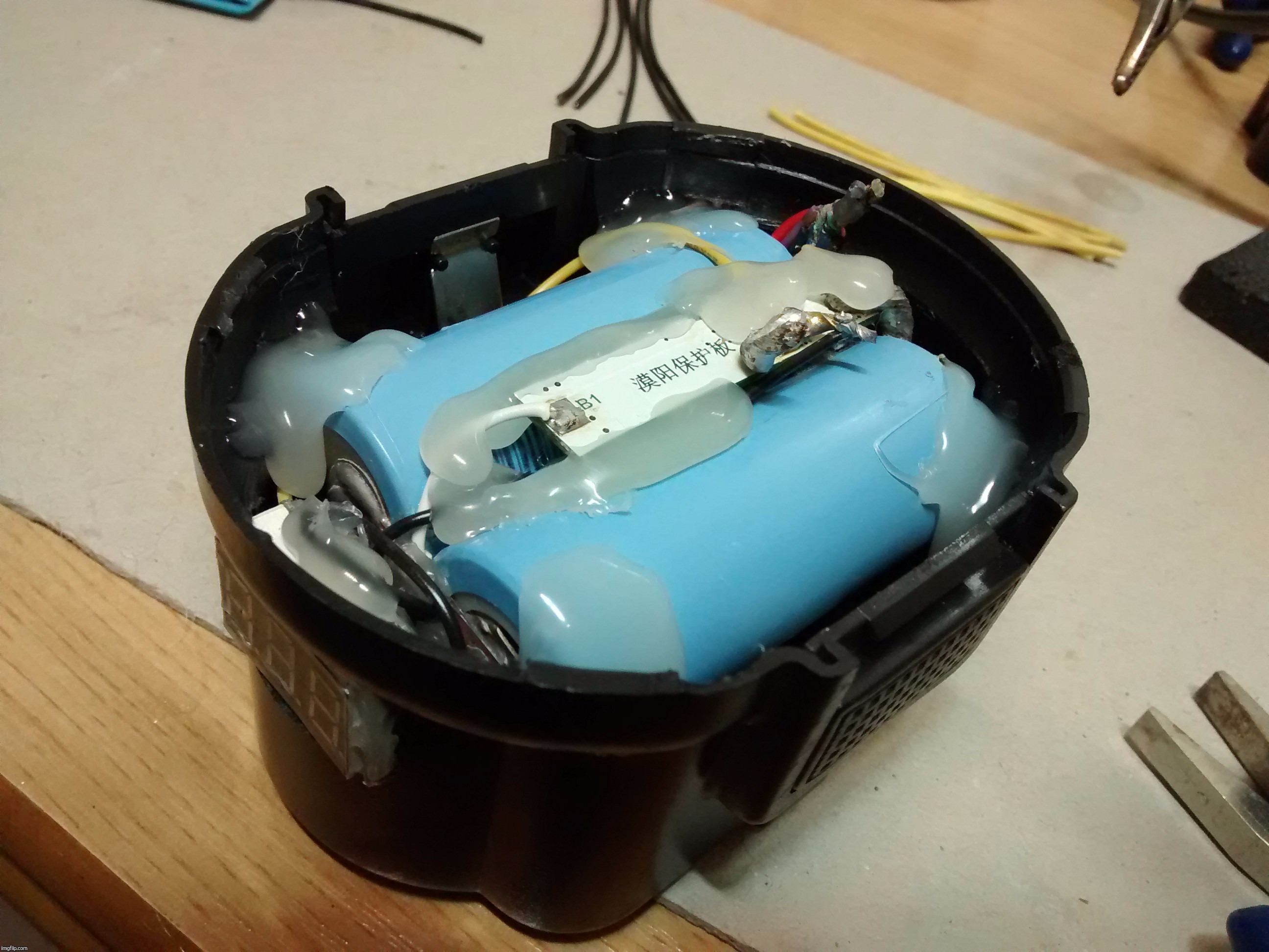
Somewhat rearranged guts. Ended up adding more hot glue over the contacts' stuff before semi-low temp soldering the cables and closing.

Not fully tested yet, but the very little no-load voltage drop with the drill fully running (≈0.16V) tells me the stuff is working as it should.

Massive torque available now…

Cheers ^:)