I’m new to these forums and opened the account to ask for help (please, please, please) with my planned circuit…
• *Power Source:
Basically, I want to power an LED circuit from my PC’s PSU Molar (12v red wire). The internet shows the red wire to be 12+ and the yellow 5+ - does this mean that its safe to assume its 12v, or could I end up overpowering and destroying everything?
• *Circuit Specs:
Voltage input: 12v, LED through power: 3.1v, MA 30v x24 LEDs
• *Aim of the Plan:
I will have 4 fan shrouds at the rear of the case and 2 in the middle (above the motherboard). Each has 4x5mm LED holes so I’m trying to plan a circuit of 16 (rear) & 8 (middle) LEDs for 24 in total.
• *Research:
*I’ve used LED online calculators but they only seems to show 3 LED’s in series per resistor and this would be very difficult to plan due to distances. The calc’s say to use a parallel connection of 8 wires - leading to 3 LED’s in Series followed by a 100ohm 1/4w Resistor on the ground wire?? Shouldn’t the resistor be on the positive wire or is the ground wire okay?
• *Solution?
*Can I plan out a parallel connection of 6, leading to 4 LEDs in series, then which resistor should I use? Would another option be to have maybe 3 wires in series, leading to 3 resistors, then splitting to 6 LEDs (to keep things simpler?). I cant see how 12v can be enough to power 24x 3.1v LEDs regardless of being series or parallel. Can it actually even work at all? I know the calc’s say it can but I’d rather a ‘real’ person say yay, nay or maybe please
I know there’s are a few queries here so if anything doesn’t make sense, I’d be happy to clarify. Please could you take a look as my research has taken me this far, but my experience is zero and I’m struggling to find a similiar situation in forums!
Can’t help you with the LED wiring, but you definitely can use the 12v PSU output for your LEDs.
I have hooked up some LEDs to my old computer’s PSU, but it was a car LED kit so all I had to do was cut the positive and negative wires and solder them to a female molex plug I took from an unused adaptor, by using a plug I am able to easily remove the LEDs.
You could split your LEDs to two or more circuits if a single 12v power source is not enough.
Do you have a schematic of what you are trying to do?
Seriously draw it out and look at it that way...most of your questions can be answered if you have a schematic in front of you most of the time.
When you parallel a circuit it divides the voltages equally between the paths
So 12 volts / 3 paths = 4 volts per path to ground
In the above if you put in 12vdc on the input, and only 4 legs, each led in the legs would have 4vdc on the input side. What is the target current of the LED's?
If you have 4vdc (12vdc total divided between the parallel ckts) and want 13mA per LED, then
Source Voltage = 4 volts
Voltage Drop = 3.1 volts typical for a blue or white LED
Desired Current = 13 milliamps
(4 – 3.1) / ( 13 / 1000 )
If my math ain't screwed up, you would need a 69Ω resistor in line with the LED's or as close to it as you can find
The "Anode" of the LED is the positive side
So lets draw a picture
Above, you have 2 paths 6vdc per path
you have 16 leds on path 1, 8 on path 2, you will have 6vdc in on each led, do the above math
(6 – 3.1) / ( 30 / 1000 ) = 96.66667, you will need a 100Ω resistor tied to the anode side of the LED's
Been a LOOOOOOONG time since I used the electronics fundamentals I learned in HighSchool...my brain hurts :D
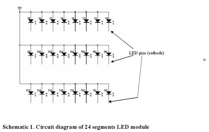
Unfortunately not but I do have a rough diagram of my PC water cooling upgrade. From this picture, 4 LED’s will be on each extender (4 rear, 2 middle) excluding the bottom right extenders. Looking at your schematic - that’s exactly what I’d like to do!
Edit… I’ve remade your schematic to show my specific plan:
Thanks Hawk, yes that’s what I thought too. I was just worried that by using 4 volts on each path, if that’d be enough for the 8 in series afterwards so thank you.
Sorry mate, what are the 4 legs and nbsp please?
Here are the LED specs:
24 diodes
through power: 3.1v
MA 30v
Would you say my plan seems worth it? (despite the complication). I’m well motivated for the effort but am I potentially creating unnecessary risk / or need super expensive resistors?
Your brain hurts? I’m not surprised! Mines melted away! haha
Edit… I’ve re-read this a few times and its starting to sink in! From my understanding then, this can work and all I’d need is a 100ohm resistor on the anode side of each diode then job done? The only other factor was that the LEDs I’m looking at are rated for 30milliamps, would my circuit power those correctly please?
No, the voltage isn't divided by parallel circuits, they'll all see 12v, assuming you don't exceed the source's ability to supply current. The problem you might have with 4 LED's in series is the forward voltage of the LED's are added if in series and may exceed 12V, so effectively no current will flow.
Yeah…I thought about it afterwards, but I had already logged out to fix it, the voltage at the input would be 12, so the math is different
Like I said, its been a LOOOOOONG time since I have done the fundamentals of circuits
I studied this back in 90-92...so it's been a while and there are three things you loose as you get older, the first is your memory............and I can't remember the other two
Thanks everyone and thanks for the link David - This is the calculator I’d used which shows the resistor on the ground wires? I didn’t think the ground wire would do anything (but then my knowledge of electronics is incredibly limited!).
This site shows them all in a 8 parallel connections to 3 series LEDs.
What I’d be looking for is:
2 parallel lines- one with 16 LEDs in series, one with 8 LED’s in series or
3 parallel lines- With 8 LEDs in series on each.
My understanding is quickly growing: For series connections, then all draw the output rated voltage of 12v until the power source cant supply any more. So… I’m thinking if I can find LEDs with a 3.0v forward voltage, then I could have PSU - 6 Parallel - x4 Series with a 1ohm resistor.
Please correct me where I’m wrong Any reccomendations for LED’s that would suit my purpose?
Each led requires 3.1v so if you want 8 in series you need (8*3.1v) 24.8v supply.
Try an array using 4 led in series, they will only get 3v if your psu puts out exactly 12v, ATX psu’s have a 5% (10% for older units) tolerance so it could be anywhere from 11.40v to 12.60v, stick a MM on it and find out the exact voltage, 12.5 is ideal for 4 led.
You could string as many series of 4 as you want like this,
I’m guessing the 12v wire for my PSU may be slightly higher then as its an Antec 1200w PSU. I’ve looked through many multimeters and just ordered one :).
When I test it, I’ll use the calc again and then order the appropriate resistors
Thanks for taking the time to go through this with me. Sorry if I appeared to be stupid because of totally novice questions! I’ve learn’t a lot today and its a lot simpler than the picture I’d created in my mind over the last few days.