The specs of Opus 2.1 has specified voltage deviation <0.03v @4.2v.
In your case, both –0.02v or +0.02v is still within the specs.
Personally I would be happier to see +0.02v because it’s less likely for the charger to overcharge.
Would a small resistor between the pads correct or even fine tune the accuracy?
Hi hohol_m, thanks for your msg :), I’m very sorry that this charger made trouble for you, but I think your problem is something technical and I’m not qualified to answer it, so I will contact with Henry Xu, the engineer of Opus, any update, I will let you konw, could you please wait for some days.
Have a nice day ![]()
Hi CSgearbest
also strange is charging mode 4.35 V.
Upon reaching the voltage 4,20-4,22 V the charge current drops to 100-120 mA.
And so it goes on for several long hours. But the charge does not occur. Maximum receive a charge of up to 4.25 V
![]()
Interesting results on the voltage measurements. The input to the cells is definitely different from what is actually happening at the terminals. I get different reading on each bay from dead-on on bay 1 to 0.03 high on bay 3. I haven’t done anything with the J1 jumper. I have not verified if it is closed or open (probably closed as mine is from the 10/01/14 batch). I think this one is “leave it alone” unit. Although the fan is annoying, it isn’t anything to write home about.
Overall it is a fun little unit for getting some idea of where your cells stand from a usability standpoint, but for serious charging, I’ll stick with the XTAR. It is also my only NiMh/NiCd charger that has some level of readback.
It is what it is. $40 worth? Yep. More? Nope.
Thanks everyone for all the feedback.
NiMh lower 0.03 V.
cleared J1 higher 0.01
![]()
Okay, add one more dead fan to the list.
GB, what can we do about this? order WW1410011910348998
thanks for your information ,i guess many people here can
get a lot .
Hi hohol_m and NightSpy, all of your technical issuses I have made a feedback and sent to our related staff to communicate with Henry or other related party, once have new updating, let you know ;).
I got my copy of the 2.1 version last week and have been using it quite a bit. A few thoughts:
- Mine also read about 0.05V high, and was charging cells to about 4.15V. I cleared the J1 jumper, which seemed to alter the displayed voltage but haven't tested since then to see what it does to termination voltage.
- The fan is very loud on mine. I took it apart right away and packed the fan with synthetic grease. The fan was still incredibly loud, so I investigated further. On my copy, the fit between the fan, case, and outer plastic cover is so tight that it actually distorts the fan a bit, causing it to be louder and probably wear out much faster. I removed the outer plastic cover and with the grease the fan is much quieter now.
With a bit better quality control, higher quality components (FAN!), and a bit more thought to design (voltage switch), this will be a top charger. Until then, it's a good charger for a Flashaholic, but not for the general public.
I believe that voltage switch should never be available to the public. It is right where it should be, hidden from view, available to anyone willing to take the unit apart. It is a hidden feature, only available to those that know it’s there and know how to use it. To anyone else it is just plain dangerous. Speaking of danger.
How many here would leave a cell on a charger unattended?, not I. Now imagine you are the designer of a charger that is sold to the general public. In effect every one of them is used to charge cells unattended, by you! If I was the designer, I would feel very uncomfortable with that.
That J1 says a lot about the thought process when this charger was designed. No doubt there was a concern about some chargers being out of spec and charging too high. The spec is +\ .05V, so a simple safe solution would be set the charge to 4.15V and those that charge too high would be at 4.20V. Problem with that is those that a charge too low would end up at 4.10V. Everybody would be safer, but some would be very unhappy. So the voltage readings were set to read .05V higher than what they really were, people were supposed to be fooled. J1 was included in the design to set or not set that final .05V. It wasn’t jumped at first in v2.0, but probably after some sleepless nights, it was decided to be jumped in V2.1.
From day one there was some concern and the designer chose sort of a sneaky way out.
Today I tested the KeepPower 3400mah cells I’ve been using on the bike. Very well used and likely well over 500 top-off charges and at least 100 near-full charges. one read 3105mah and the other 3171mah. This actually makes me happy, except the fact that I don’t know what the test state was for sure. But I did notice this. I always fully charge on the XTAR charger. I know it terminated perfectly every time at 4.20V. When the test was started on the Opus V2.1, it started its charge routing as normal and then showed 4.25V just before it went into the discharge for the test. Again, I left the J1 jumper in place.
Tomorrow I will test my brand new 3400mah evva-tech cells from Mtn Electronics. This should be interesting. I’ll do the same, top them off on the XTAR WP2 and see if they come close to the expected capacity according to Opus.
However, I am skeptical about all the readings. I know the meter is not reading the terminals. It is doing some level of interpolation. That J1 jumper could be affecting a lot more than termination voltage including internal calculations. I know the same thing happens when it reads voltage on the discharge and doesn’t come close to the terminal voltage (in this case always reads high). The display is simply =some= internal reference, but who knows exactly what.
Also, per the review on the charger, this is =not= a true CV/CC charger and this does cause some really wild readings during the charging phase at the terminals. Yes, this unit is feature packed in firmware, but the deviation in the CC portion really is what makes this thing suspect for a reliable charger. It could well be that the J1 jumper is all about how it manipulates the pulse current for emulate the CC cycle.
Reference: see conclusion here - Test/Review of Charger Opus BT-C3100 V2.1
Hi,
I’m trying to replace the noisy fan but I would really need some help.
First of I was not able to get the original fan out without braking it. It was “attached/glued” with some sort of a white substance. It’s also possible that it was already broken and that’s what was causing it to rattle. For reference the fan that was inside was: HUASIND HXD2507S12M, DC12V, 0.10A, with the size of 25x25x7mm, 10000RPM, 1.1CFM and 25dBA. I really don’t know why a bigger, more powerful and quieter 25x25x10 fan wasn’t used (it wouldn’t be perfect either but certainly better) and why the mounting is so strange.
I’m trying to replace the fan with SUNON MC25101V2-000U-A99 (25x25x10) but it will not fit without some changes to the chasis and/or the motherboard. I would be really grateful if someone who has already switched the fan posted some pictures and a more detailed description of what was done.
Best regards,
Crocodil
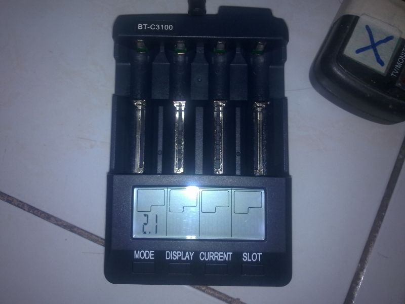
Henry Xu of Opus sent me two pre-production v2.1 chargers. As you can see in the first pic, it does not yet have the Opus logo printed in the upper right hand portion in the housing of the production model. (mine is the same non-logo model reviewed by HKJ in this thread)
The stock fan of the v2.1 is actually much quieter than the ones in the original versions. I also have the v2.0, btw.
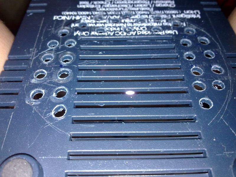
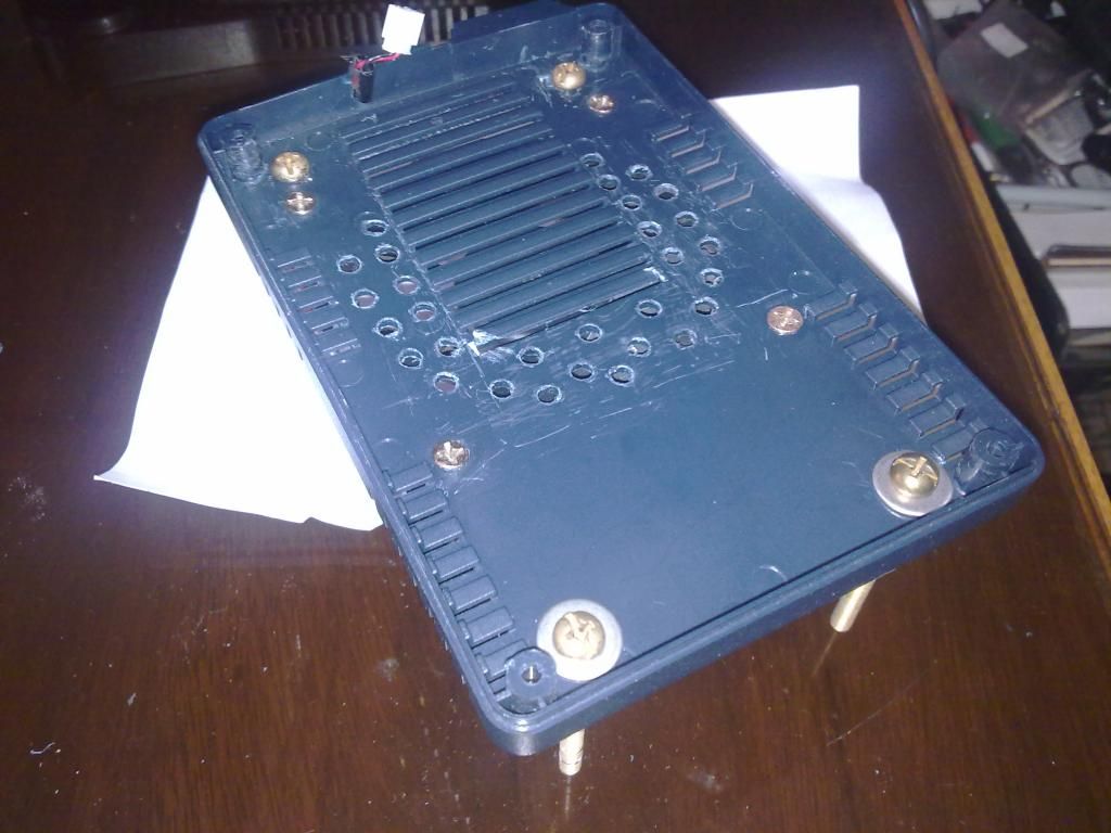
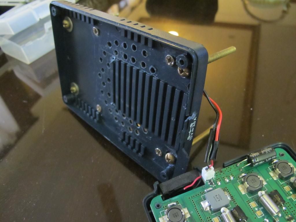
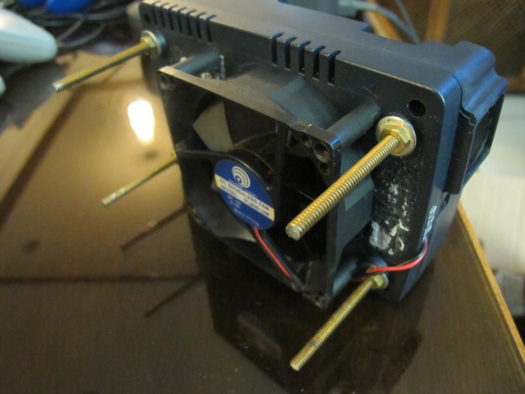
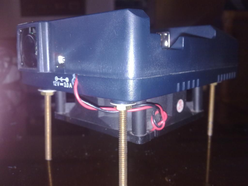
I experimented with one of the charger’s cooling by putting a 12VDC, .13A, brush-less fan salvaged from common ATX PC power supplies at the bottom of the charger. I cut the wires that powers the stock fan then connected it to the new fan at the bottom. The air sucked by the new fan passes from the top, through the charger’s 4 cradle rails, cooling the cell/s and electronics below and finally exiting through the original horizontal cooling and round holes I made. My project will not win workmanship awards nor a beauty contest but nevertheless attained my goal of using a quieter fan.
Since the fan pulls in more cooling air than the stock one, it is not only more quiet but it turns off automatically much earlier since it cools the charger much faster, triggering the sensors that control the fan to turn off the power to the fan much earlier.
! !
!
! !
!
! !
!
! !
!
Note that the charger’s original power supply wire still controls the new fan (automatically switches the fan on/off as needed). I cut the wires going into the original fan and transferred the white connector to the bigger fan leads.
! !
!
! !
!
Make feet with fuel line, it will lower the vibration, that thing looks like it would gouge a wooden surface.
I like the concept though, gotta be overkill, and that is always GOOD ![]()
Later,
Keith
tatasal I can safely assume you’ve voided your warranty ![]()
@tatasal: This is one hell of a tuning ![]() I’m sure it’s now much quieter than with the 25mm fan
I’m sure it’s now much quieter than with the 25mm fan ![]()
What have you used to drill the holes in the base of the chasis and how big is the fan (80mm?).
The fan is about 74mm in diameter. I made the holes the primitive way. For lack of owning a drill, I just drove a hot soldering iron onto the base.
Actually the original horizontal slots already have holes in them already, and can be seen when viewed at an angle. The round holes are just for additional air movement.
Ha, look what I found in my parts box… still in the bag!

@ NightSpy
That fan of yours is better. No need to put the charger on long ‘stilts’.