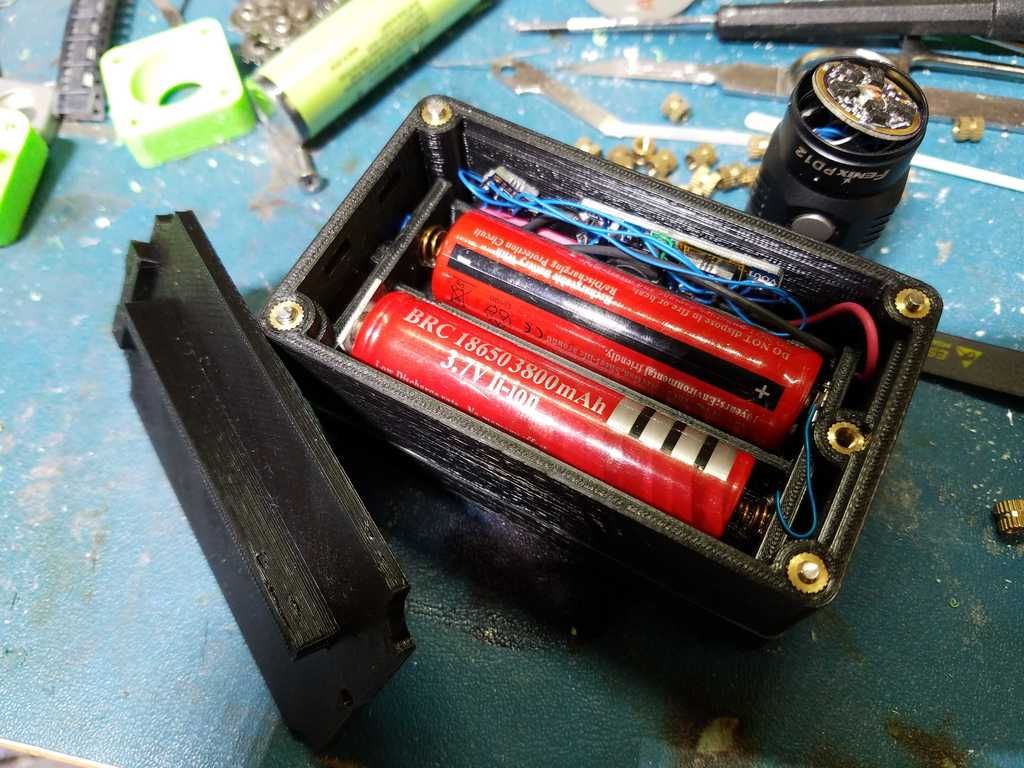
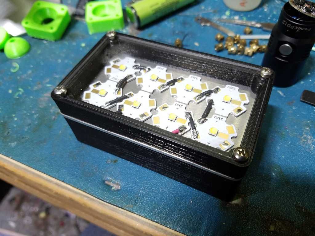
3D printed 18650 light, playing with the idea.

Hello!
Quite some time ago i sparked the idea to build a flashlight, it is a few months later now and i have a rough idea on how to do it.
In my parts bin are about ten 18650 cells, 20 LED drivers, a few Nichia LEDs and a 3D printer, all that needs to be put to good use.
So i am set on these four things, here is what i came up with so far, just made some prints to have something in my hand to play with:

Imgur

What i know so far, a 3D printed case seems to be viable (if printed in PETG), heat dissipation of the LED will be a problem, 18650 makes the light a bit too big then i would like to but i do not want to buy new batteries.

LED options:
Nichia NF2L385AR,170 Lumen, 2700K with 83RA
Nichia NF2W385AR,197 Lumen, 5000K with 83RA
Cree MK-R, 350 Lumen, 2700K with 80RA
I am unsure about a lens, either a whide angle or none at all, i want a floodlight.
If possible i want to put a temp sensor in there so the light can regulate the power down if it gets too hot, just a cheap NTC/Resistor solution.

LED Driver with no PWM
Texas Instruments TPS61165,i have 20 of them and they fit the LED nicely.
It has a digital interface and can regulate the current in 31 steps.

With a max LED current of 250mA it gives a resolution of 8mA per step and so the lowest light output is 8mA at roughly 6V.
Since it does not use PWM the main controller can go to sleep once the current is set.

USB rechargable with build in charger
Microchip MCP73833, i still have some of them as well.
It provides a thermal cutoff while charging if the cell gets too hot with a NTC and it has 3 pin status output.
Not too expensive and i really like the 3 pin output.
It indicates “power good”, “charging”, “full” and “fault” with 4 different states instead of just a light that goes on and of.

User interface
Two buttons for power up/down and on/off or whatever idea i got, i do not want a single button.
One RGB charge indicator LED.
One dual color battery level indicator with rough battery level aproximation through cell voltage.
I never tried that and guesstimating the charge of a Li* cell by the voltage alone is not a good idea but it is all i can do with the selected components.
As a controller i have chosen the ATTiny85 because they are cheap, i want a bit more flash then a ATTiny13A and everything else is too expensive and big.

Other things
The cell needs to have a second protection circuit, i am toying with the idea of a Texas Instruments BQ29700 cell protection IC, it is fairly cheap but i hate soldering compoents without legs and this thing is tiny.

The whole, how will i mount and cool the LED is still a bit problematic but solveable.
The electronics should be fairly cheap, all on one PCB with all components on one side except the switches, if possible.
I may have to mount the switches and LEDs on the backside, i only work with 0805 SMD parts and hate leg-less packages, so i am stuck with bigger components.
With 0603 and QFN packages everything would fit on one side.

That is about it, what to you guys think?

Imgur link is bad.
At 250mA max don’t need a temp sensor
The attiny can easily handle voltage sensing and cell protection, protection circuits have parasitic drain.
0805 smd parts will fit on 0603 pads
Is one switch a clicky and the other momentary or is power also an e-switch.
With no parasitic drain a cell will last years just sitting there at nominal voltage.
Don’t gift it or sell it to someone who doesn’t get it. Liion cells can be dangerous with or without protection circuits and ignorance = genius when coming up with unforeseen ways of sidestepping design parameters. no such thing as idiot proof.

Thanks for your reply!

Sorry, the forum software really does not like the link it seems.!
I can not get the link to work… i re-uploaded it:
Imgur

The test i ran says otherwise, the LED gets too hot with just a bit of aluminium sheet.
That is about 1.5W of heat produced by the LED.

The drain of the TI part is way lower then the ATTiny in sleep mode, 25µA in operation and around 100nA in shut down, once the UVLO is triggered.

My pads are a bit bigger, i hand solder the stuff.
I just do not do this stuff often enough to be able to rationalise reflow soldering from a budget perspective :slight_smile:

Both are soft switches, controlled by the ATTiny.
I expect the circuit to be drawing about 100µA in “standby mode”,
with a battery capacity of around 3Ah i am comfortable with that.

The cell will be build in/non removeable and the charging port is just a micro USB connector, not that much can go wrong with that.
Leaving out proper cell protection, even if the only user is me, is a bad idea.

If it overheats with only 1.5W then you probably need to figure out how to get more than a bit of aluminum sheet in there. I made this one that does just fine at 13.7W(4.5A/3/4V) for short periods and 4.7W(1.5A/3.2V)continuous. In any case I would think it preferable to have stable operation at 250mA max rather than a step down from there. 31 steps from there to 8mA is maybe 28-29 in excess. Not trying to be mean here just my opinion based on experience with 350m lights and at 250mA/6V it’s comparable to .5A/3V which is on par with many single AA lights that don’t get too hot or need very many lower modes.
I think “protection circuit” is a misnomer possibly leading to a false sense of security but if the concern is of a short circuit then not misplaced and I won’t tell you it’s a bad idea. Just don’t forget that you are your best protection. If the cells are to be built in permanently and charged in place then instead of individual cell protection you might consider BMS (battery management system)which monitors each cell individually as well as the battery as a whole both in charge and discharge conditions. You asked for input, that’s my .02.

Hello and thanks again for your reply!

In case i came over a bit grumpy, im sorry, your feedback is apreciated! :)

Yes, i have been thinking about that, i have come up with another way but i am not too happy about it.

I can do a aluminium body, no problem, but... the whole idea is to make this thing only with a 3D printer, it is kind of a design challenge, just two PCBs and the 3D printed parts with a few screws. Nothing else.

A custom aluminium PCB cost about 4 bucks with shipping when i order 10 pieces and i want to use that as integral part of the body, sandwiched between the head and the body of the housing.

So... as a design challenge that is my only "heatsink". At around 100mA that works just fine, at 250mA it gets too warm.

Another way would be to just stack two of the aluminium PCBs back to back, that only incrases the mass by double but not the surface area.

No worries, i never build a flashlight, every feedback is appreciated!

Yes, the protection IC along with the charger form a complete BMS, they monitor the voltage and current during chargeing and discharging including the temperature of the battery itself.

Over voltage, temperature and current protection during charging.

Under voltage and over current during discharge.

And the ATTiny with the TI part forms a 2 level discharge protection, the ATTiny shuts the light down below 3.3V and then if it gets further discharged the TI part cuts it completely of at 2.8V before the cell gets damaged.

As far as i can make it out that is the "industry standard" for every build in Li* battery in handheld devices like your phone.

You could use a protected 18650 but they cost double what a unprotected cell costs and, this is the important bit, i only have unprotected cells and do not want to buy new ones.

Since i use only a single cell i do not have worry about balancing and i get the 6V for the LEDs from the boost driver, i mainly choose this path because the Nichia LEDs are very cheap at just 1,50 Euros and are authentic and i got the LED driver ICs at very low cost.

Instead of an aluminum sheet, can you print the top/heatsink with a metallic filament? Filament Innovations has a good aluminum (40%) version that prints pretty well.

Interesting idea, thanks!

I made a very rough mockup on how the thing is supposed to go in 3D printed body:
Imgur

Not the real shape and form but so not too much has to be imagined.

Maybe even print metallic filament fins?

a 1xAAA would be super light, as well as having less heat issues…

heat is only an issue with high output - 18650 can have low output too :slight_smile:

wle

The wattage he’s considering is already comparable to a single AA light. It’s not the cell he’s using but the lack of enough metal to disperse the heat. At the moment the design is of a point source for heat surrounded by insulation. I’m intrigued by the possibilities and the metallic filament might be enough to solve the issue.

I think i came up with a semi-decent solution that should work:

http://i.imgur.com/OFcwDGC.jpg

Since the PCBs are damn cheap i can just use two and put two spacers between them and screw the whole sandwich together.
The spacers are easily made since they are just two aluminium tubes, maybe i can even glue them together with thermal adhesive.

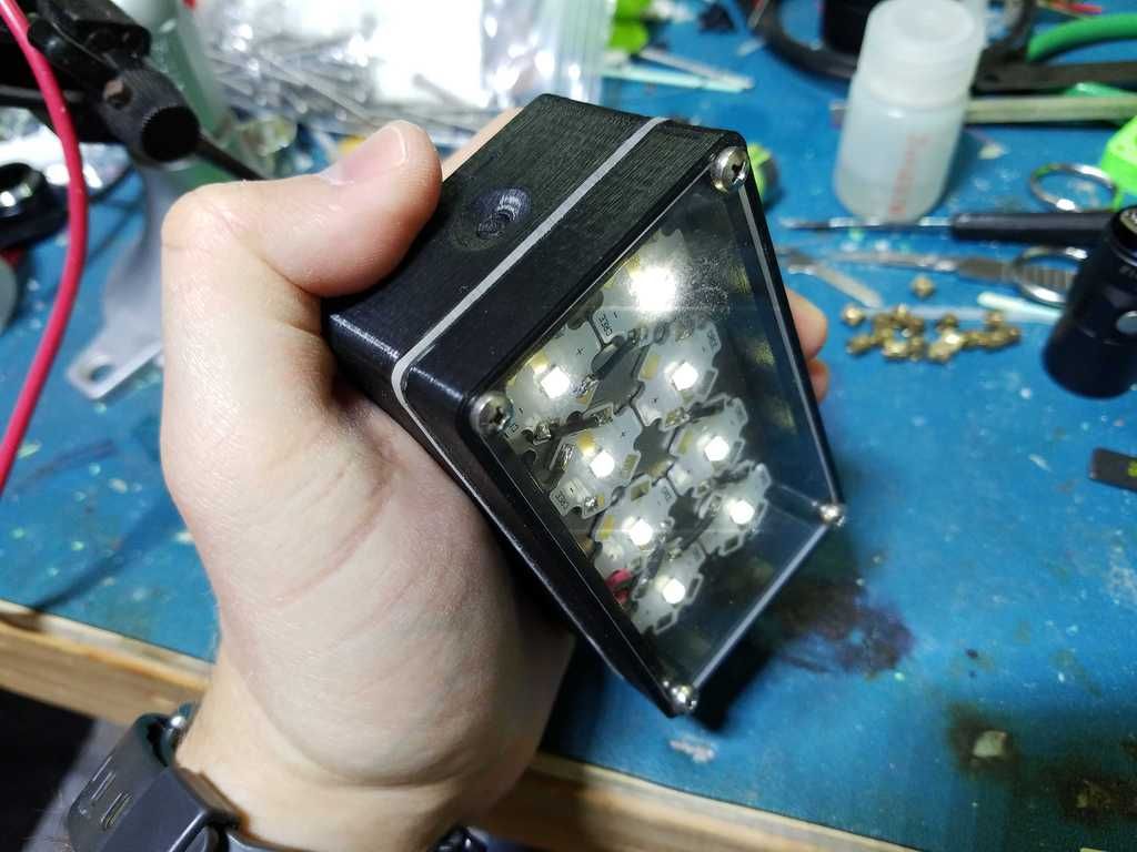
A few months back I made a 3D-printed 18650 light. It’s a wide-area camping light, running 8 XP-Ls in series on a boost converter from 2 series 18650 cells. It was primarily made as a test of hacking the MT3608 boost converter modules to turn them into constant-current LED drivers. It actually works pretty well - you can dim by PWMing the enable pin, as long as the frequency is pretty low. This one is boosting from 8V to 24V at 500mA (output). The firmware is my basic single-channel momentary switch UI, which is essentially a stripped down version of MELD. I mentioned in the video below that I made it open source, which I thought I had, but now can’t seem to find where it’s stored! If anyone is interested I will be happy to share the source code.


A quick demo video:

Thanks for the reply!

You have no problems with the heat in that setup?
It looks like you mounted all the emitters on one sheet of aluminium and sandwiched that between the case halfs?

Yep it’s just a 1/8” sheet of aluminum that comes all the way out to the outside edges. I ran it for about an hour while camping at probably ~50% power and it had no issues with temperature. I haven’t run it at maximum (12 Watts) for any significant time though, it would probably get pretty hot if I did.

I think i finally got a decent way to get the thing cooled, ill try to get something drawn tomorrw and post it.

Maybe someone is still interested :slight_smile:

Forgot to ask what kind of 3D printer you have.

It is a “Duplicator I3 V2.1” that is often re-branded as a “Monoprice Duplicator I3 V2.1”, it is a damn nice printer for the price i think.
The prints look way better then i thought they would be, very happy with it so far:

This seems to be a viable solution, it is not pretty but gets the idea across.
I upgraded to two Nichia LEDs, they get to around 394 Lumen for cold white and 338 Lumen for warm white at max current.
This perticular type is used because i can get them for only 79 cents a piece and they run at 129 and 159 lumen per watt efficiency at 100mA.
Those are pretty good numbers for the price it think.

This still is a very odd combination of parts and LEDs used but the idea is odd in general.
Since the metal core PCBs are rather cheap i can just use 3 of them, one has the LEDs on it, the others just serve as a heatsink, if that is not enough i can just stack more PCBs for more surface area.
Everything sandwiched together with spacers and M3 screws, M3 since i use them everywere in my projects allready.

The cables for the LEDs go through two small aluminium tubes that to through the stack, they serve as alignment pins as well.

There is no optic, this is very intenionally a flood light, the “lens” i plan to use is from a LED strip cover.
A mock up with some duct tape and my bench supply and the two LEDs that i have showed that the beam looks nice that way, it looses a bit of brightnes but finding a proper optic for this was not easy.

Ledil makes some interesting shapes for optics. It’s looking more reasonable now.

I hope you put those Ultrafire cells to recycling soon
Such nice emitters and then those 600mAh fire ells