Hoop, that is a heck of light you built there and I LOVE throwers. As I have mentioned, I have seen a lot of builds with this host, but none one quite like yours.
Nope, this is going to be a flooder almost like a mule. It is what it is.
Hoop, that is a heck of light you built there and I LOVE throwers. As I have mentioned, I have seen a lot of builds with this host, but none one quite like yours.
Nope, this is going to be a flooder almost like a mule. It is what it is.
OK, tonight the glue dried and I hooked up the modules to the stock 12V battery. It draws 6.25A on high, approx 75W
It is definitely a flooder and is almost non directional. Here is a video of this light running on 12V. The reflective sign at the bend in the road is about 225 yards away. It doesn’t show in the video, but I was waving the light around with out much effect as there is no hot spot.

Compare this to a 6 XML-2 SRK modded that draws 18A from 4P 18650. approx 72W
You should be able to click each video and watch them both at the same time. It even looks like I caught the same car in each shot, even though they are 6 months apart. ![]()

Thanks for the vids, there is not that much difference between the two (but even with your expensive glue the new one should cost far less)
Awesome build!
OL, you’re too kind, thanks.
I could stop here with the build. For not much effort I have a light that was is improved over the original.
But now comes performance enhancing attempts, the Li-Ion packs and active cooling
We shall see……, hopefully brighter than ever.
Nice build! I like the tint in the video ![]()
Here are mouse over pics comparing the upgrade to 5S2P Li-ion compared to the 12V SLA battery.
6XM-L2 SRK at 18A vs 18V build
The beam pattern seems different
Yeah, much more light in every direction!
Before I started this build, I knew this light would perform much better with the increase in voltage. I had to get it up and running on 12V first before I proceeded further.
When doing mods or builds, I believe it is VERY important to know that my efforts will be worthwhile.
I completely agree
Coming up next is the actual mounting of the 18V Li-ion pack in the head of the flashlight. So far all I have done is create the power pack and the remote charging adapter.
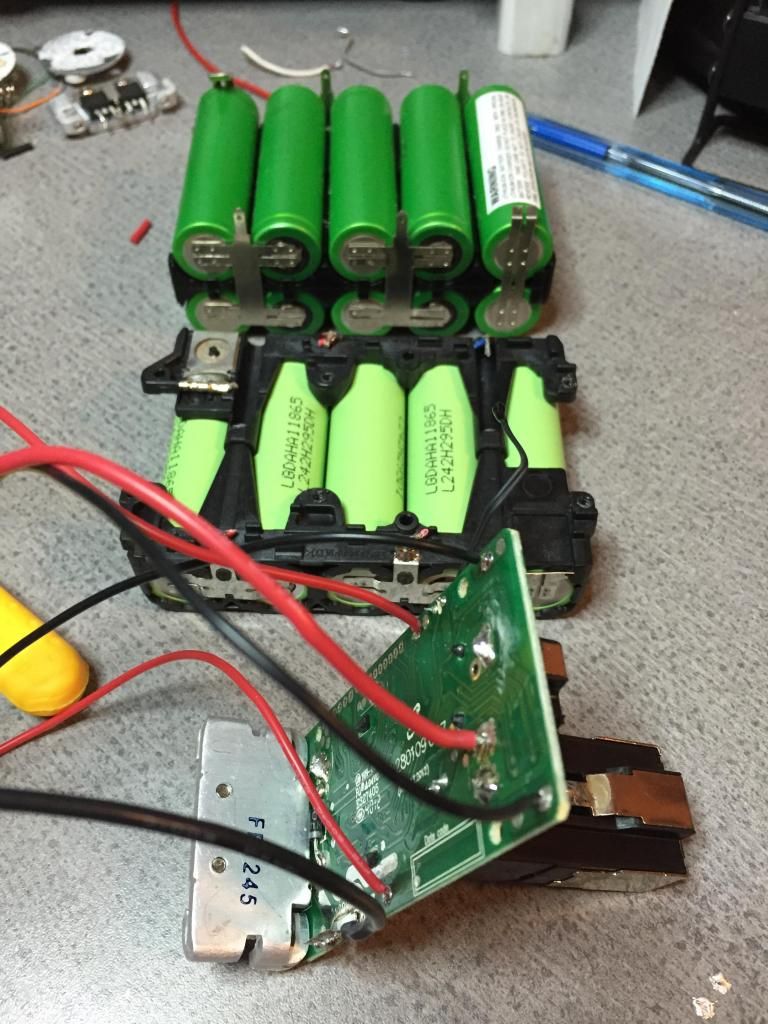
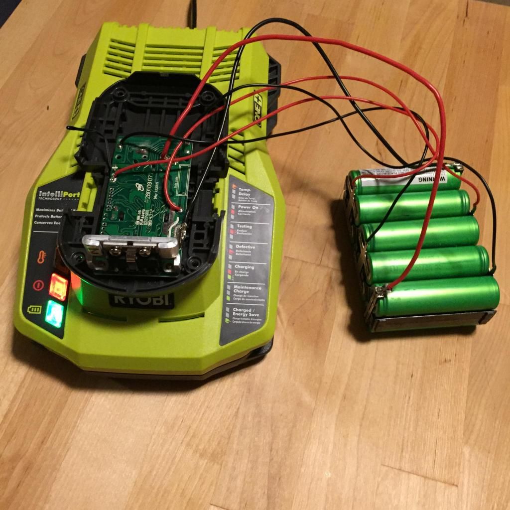
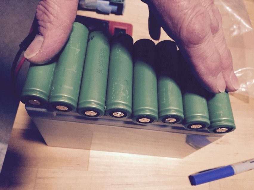
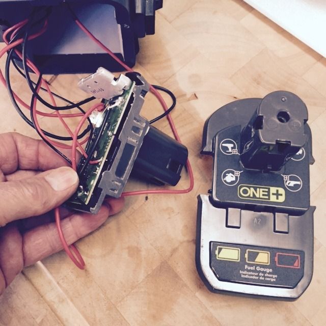
Here is the original BMS board from an 18V Ryobi 5 cell drill pack that I got from the recycle bin at Home Depot. Behind the 5 cell pack is a 10 pack, 5S2P, from the Porta Cable drill pack that I mentioned earlier. This pic shows the new lead wires that I soldered onto the BMS board so that I can connect it to the 10 cell pack.
OK, I have now wired the BMS board and charging header onto the new 10 cell pack. This is just temporary because I want to make sure that the pack will charge up in this configuration.
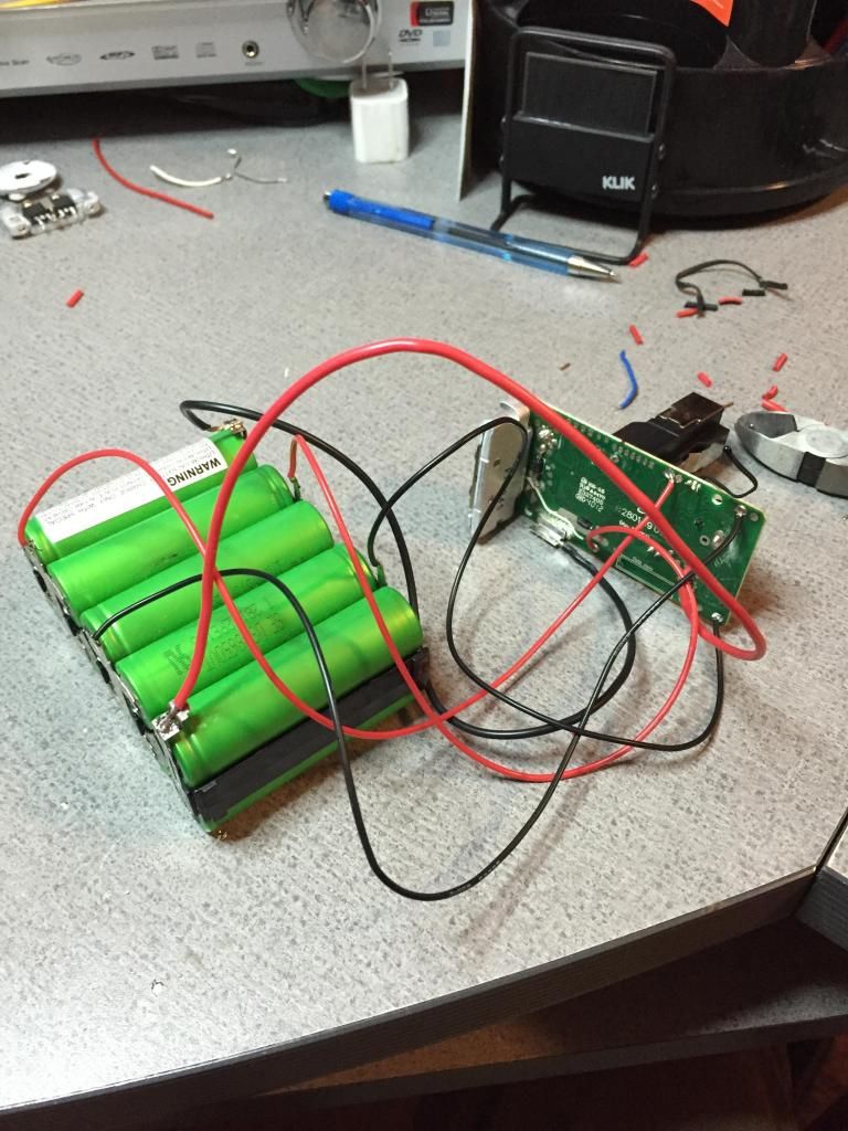
Here it is in the charger, and it charged up just fine.
This next step is to check the capacity of the charged pack. I gutted an old Ryobi Ni-Cad charger and added some Binding posts for output. I had to file down a key that would prevent a Li-ion pack from getting inserted in the slot. Here is that pack discharging into a 3 ohm, 185 Watt resistor. That resistor is resting on 2 aluminum heat sinks and it gets HOT! Hot enough to melt any ordinary lead wire insulation that should happen to touch it. I have a 110V chassis fan running to the right of it to keep it cooler.
I normally use that fan by placing it on top of my surround amp when I push it to an extreme. ![]()
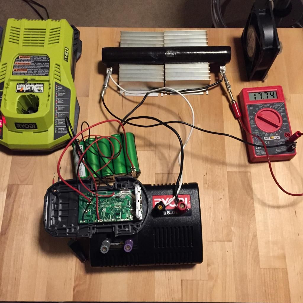
BTW, I take readings of the voltage across the resistor at intervals and use that data to ESTIMATE the capacity of the pack. Being able to estimate is a very important and powerful tool, one can not always know or calculate exactly what a quantity is, and learning how to estimate things is often times good enough.
Anyway, it turns out one of the cell pairs is a little weaker than the rest, and the capacity estimated out to about 2600 mAh.
I forgot to mention, I also wanted to test that the pack would shut down when it is depleted and also that no cell pair would overcharge. Everything is fine.
Now what is left to do is separate the temporary wiring and mount the 10 cell pack and BMS board in the light. Also to be done is separate the charging connector from the BMS board so that it can extend out to reach the charger. The wiring and the charging connector will be stored in the back of the light where the 12 SLA battery used to reside.
Then, IF all that goes well, I will install the fans. I think there will be 3. A large one with a relatively large CFM rating to “mix up” the air inside the head of the light and 2 smaller ones in a “push pull” configuration to exchange air with the outside world.
Just keeps getting better and better!
Great beam shots and power mods. Really has my brain wheels trying to turn.
The tint and CRI of your light looks great. Reds are showing up nicely. I'm trying to picture how your light will look completed. Seems like it might look a bit like a giant spider eye (or is it eyes?).
I am presenting this build primarily to the unexperienced builders on the forum. We as forum members must always realize that every day new members join that are just starting out and I think it is a good idea to have simple build content for them to see.
Lol don't sell yourself short bro, as a 'new member' this is nothing short of complicated and labor intensive! Very impressive! Granted I was able to follow along with most of what you did, unlike some other builds on here, it's like trying to read the Spanish side of the user manual lol.. Thanks and well done!
I already had it up and running on the 18V drill pack, so I knew how it would shine, After that it was hard for me to muster up enough character to actually finish it. I guess it is the laws of diminishing returns, not much more improvement for the amount of effort. Actually is just a character flaw. I have always been better at starting things than I am in finishing them.
In the first post I bragged about how “lucky” I was that a 10 cell pack would fit perfectly in the existing structure in the head of the light. While it was true that it did, weight wise it was not the right thing to do. By placing the cells in the head, and not having the original SLA 12V battery in the tail, it became unbalanced weight wise. But once again I was lucky, that same cell pack fits PERFECTLY in the tail section! The width of the original SLA battery is 652mm, same size an 18650 (18mm x 650mm)
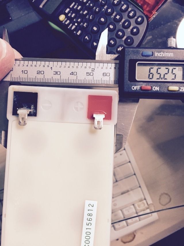
And the height is the same as 5 - 18650’s side by side
Sometimes I am just so lucky I can hardly stand it!
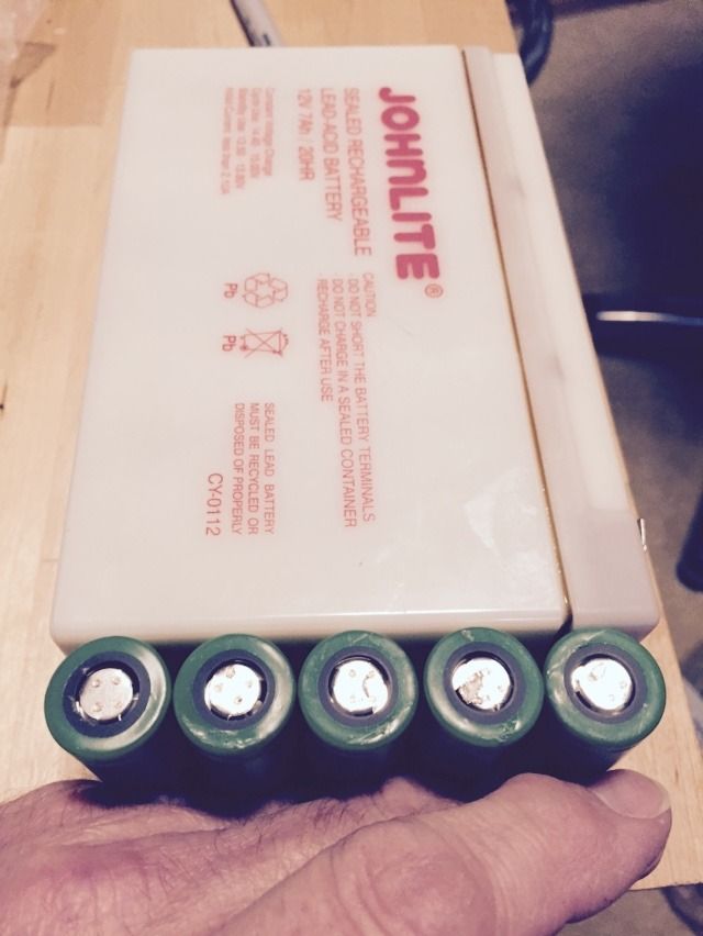
The length just happens to be the same as 8 - 18650’s side by side!
While I only used 10 cells in this light, a block of 40 would perfectly replace, size wise, that original SLA.
This light draws about 7A off the 10 cell pack and the cells are IMR. But I think it would be safe to say that a 40 cell pack could be made up of NCR’s and would benefit from the increased capacity. I would dare say the same BSM board could be used to charge a 5S8P pack as the charging current would be spead out across the 8P cells. I think in the future, If I build a bigger, brighter light and use that 40 cell pack idea, I would want to locate some new old stock (NOS) laptop batteries for their cells.
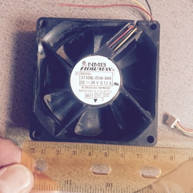
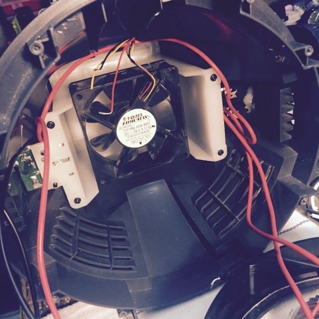
To keep the modules cool while this light is running as I am greatly over driving them, I used this old case fan I had. The battery pack when fully charged is 21V and will automatically shut down when if falls to about 13V. That’s why there is no need to used individually protected cells. The fan I am using is an 80mm, 24V fan. I must have retrieved it from a laser printer or something as any PC case fan I have ever seen is 12V. It is perfect for this application.
And of course, it fits PERFECTLY. Lucky, see what I mean? :bigsmile:
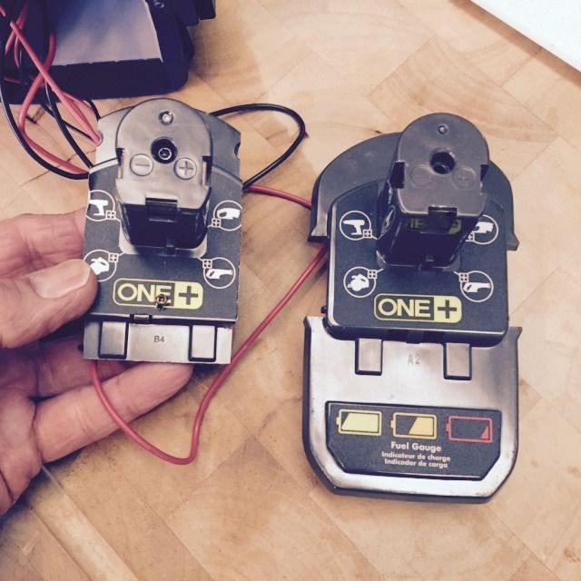
To charge the 10 cell pack i made a charging header from a cut down top of an old drill pack. I decided to keep the BMS board on the header. It’s not as elegant as my original plan, but it works. I will do better next time!
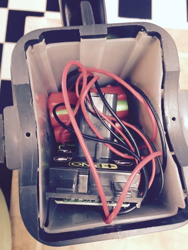
Here is the back of the light with the 10 cell pack and charging header tucked inside.
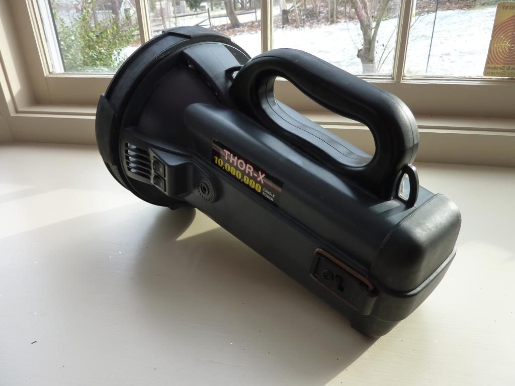
The finished light.
There are 2 switches on the side, towards the front. The bottom switch is low mode, just one of the modules is lit. The top switch turns on the other 6. The 10 cell pack and the charging header are tucked in the back of the light, behind that removable strapped on cover.
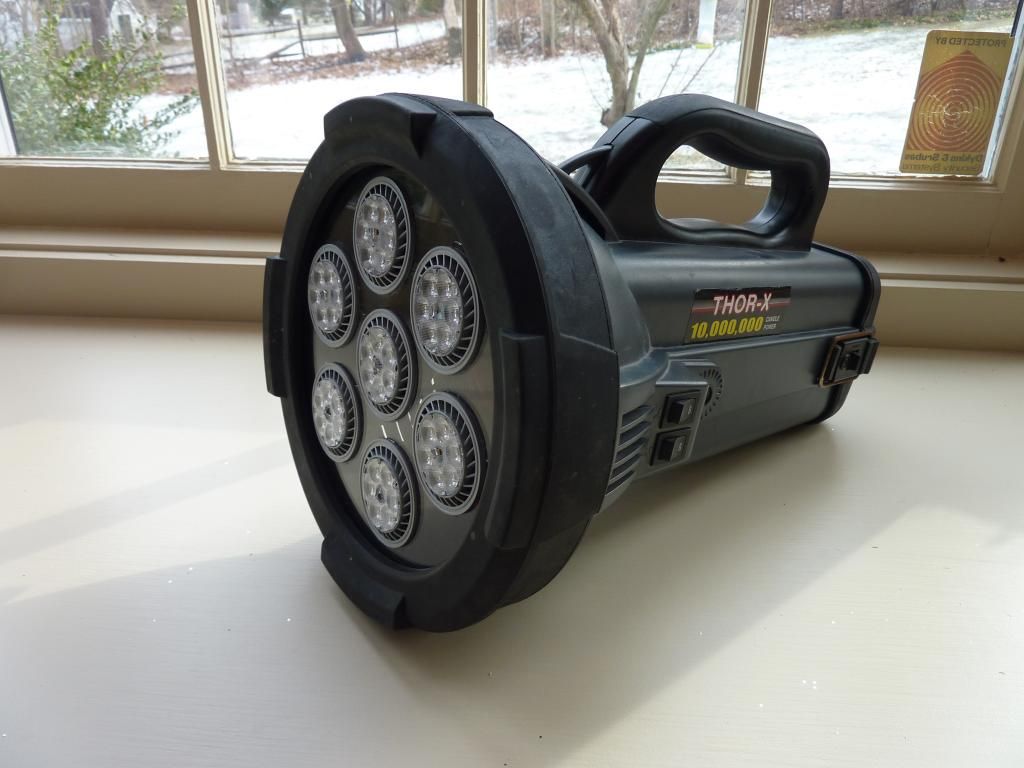
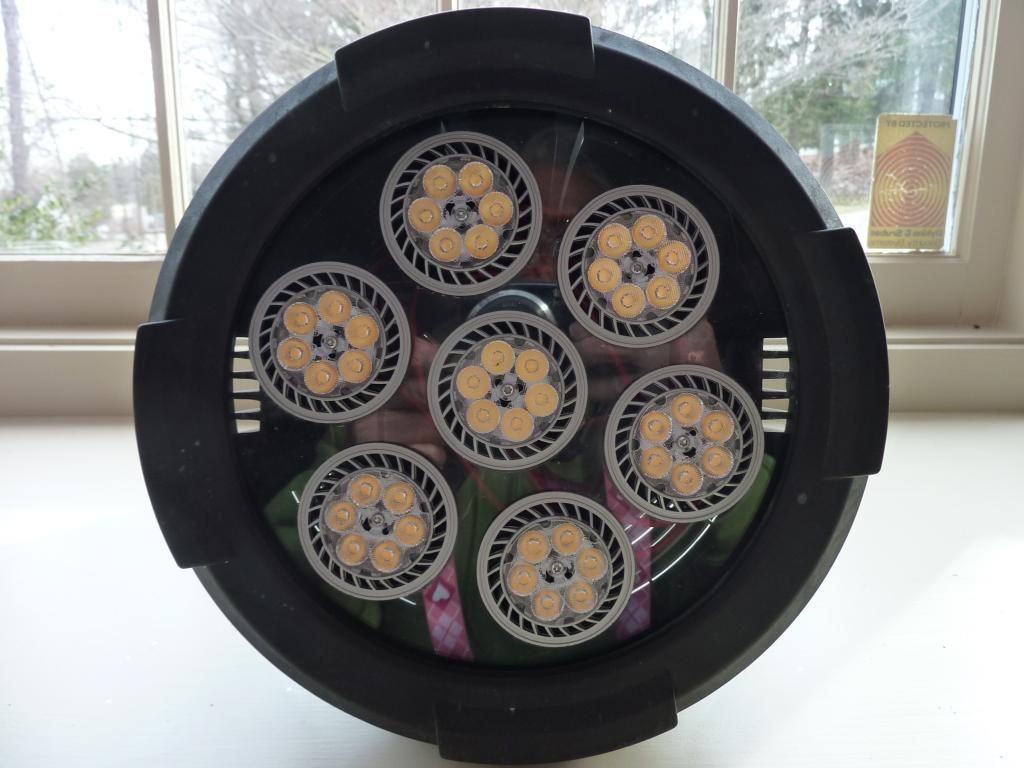
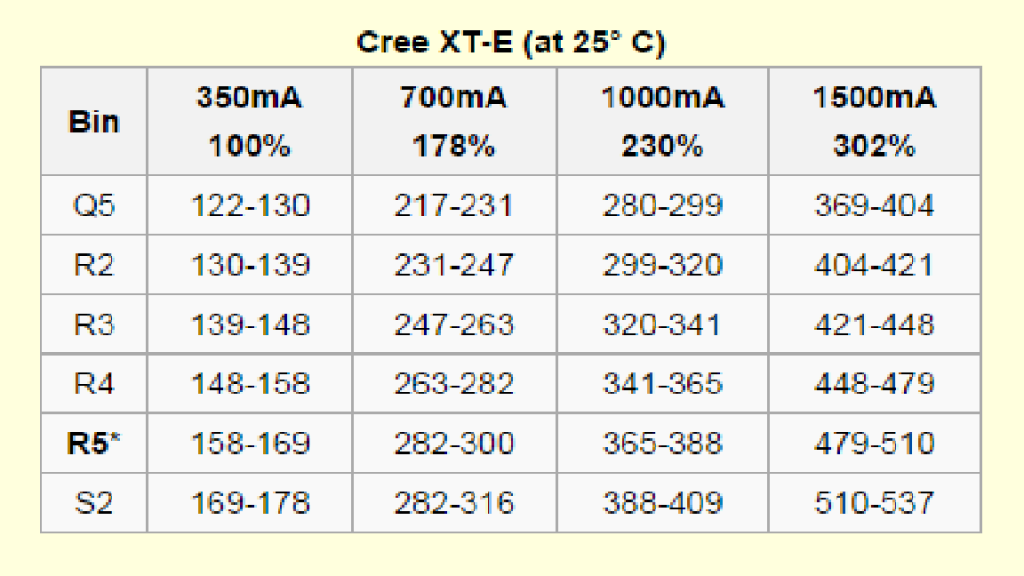
This light is NOT a thrower and it warm white in color. It does throw out a TON of light. I know it is hard to believe that 7 lowly MR-16 lights can do that, but these are high performance in the first place and they are being over driven. Don’t forget there is a total of 42 XT-E’s, each driven close to an Ampere each.
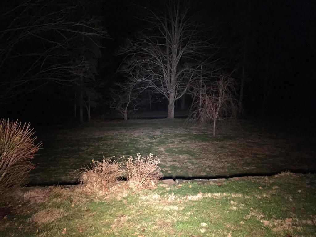
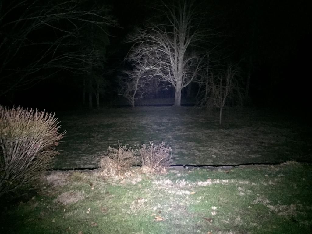
I want to find a nice open area to test the flood of this light, but until then here is a video of a test I did last night in our front yard. It is 60 yards to the street and I had to watch out for passing cars when I shot this, as I did not want to distract them. I compare the same SRK 6- XM-L2 light that is modded for higher output that was posted in a video earlier in this thread. Now though, this light is running on 18V whereas the previous video is was running on 12V. I know that 6XM-L2 light is considered a flooder, but compared to this light, it’s a thrower. The white light of the SKR looks washed out and throwy compared to the warm white flood of this one. There is some ambient light as I have LED landscape lighting all over the place. ![]()
One of my favorite lines from Breaking Bad was in the last episode when Walt drives up in his Caddy and one of the bad guys asks him what engine he had. It was a 500CID V-8 and the bad guy says
“There is no Replacement for Displacement”
6 XM-L2 vs 42 XT-E. First the SRK, then this light.

Im sure u guys might no how to take those battery holders apart but i just found out a Mag D Alan wrench works the best :)
nice mod
Thank you for the posting.
But you call this a “This build like others that I have posted about only require very limited knowledge and skills.”
Again thank you but yes I have a soldering iron and I am using flashlight mod to lean about the non mechanical world, but this is
“only require very limited knowledge and skills” well yoou think too highly of me. It is still good to see a data point and for that I am grateful, but this is not an easy mod.
Again thank you.
“(BTW, i realize that other members have put together some really unbelievable mods in the past. Probably way beyond the abilities of most of us here. This build like others that I have posted about only require very limited knowledge and skills.
I am presenting this build primarily to the unexperienced builders on the forum. We as forum members must always realize that every day new members join that are just starting out and I think it is a good idea to have simple build content for them to see.
I also am aware that there are other, more advanced members that want to see something more advanced. That’s why I want to show and evolution of difficulty in this build. First a simple build using the stock 12V SLA, then a progression to Li-Ion.
Something for everybody, although the final complexity of this will fall far short of what others have done here.)”
Dude, that's a huge build, in more ways than one. I like how you add complexity as you find more parts that seem to be perfect for your purpose. Every time I try to add parts I end up wrecking something.
Ronin, thanks for taking note of my post. You are the second person to comment on that and I am sorry.
You did quote what I said, word for word, but I don’t think that you really understood what I was attempting.
A lot of mods here, right from the get-go are beyond the reach of some of the newer members here. This build of mine was a progression, and I guess I didn’t document as such well enough.
The first step was to take a functioning light apart and install some stock MR-16 light bulbs that I bought. Granted, it took a drill press and a hole saw and some glue (which I didn’t have and had to go out and buy). I simply glued them in place and reconnected the stock 12V battery. Sort of a “bulb change” Looking back at my first post, I now realize that I sort of melded all the steps together.
In essence I did the same thing here, a simple “bulb change” Only in this post I swapped out 1 incandescent bulb for one of these MR-16’s and that was all I did.
My intent here was to show a progression in the complexity of this build, each time ending up with a functioning light. Anyone following could try and duplicate my efforts, stopping when they reached a point where they were no longer comfortable. Believe it or not, sometimes the hardest and most time consuming part of a mod is the documentation and the write up. That’s what I meant when I said something for everyone.
Here is a post of another light that was modded with 1 MR-16 that only took 15 minutes and some glue.
A really, really easy 10 minute 18V power tool flashlight mod
Nice finish. Whats next on the agenda?