I have changed posts at work and now I am over at the plant which is closing this week. It will be just us guards till they get all the equipment out of the place. I will be making rounds inside and outside every night starting next week, so I wanted something that would be bright, easy enough to handle and double as a club if need be.
I got a 4C Maglite and now I am starting to put it together. I will use 3-XM-L T6 leds (cool white), with three 8x7135 drivers, master/slave, to give 3 amps to each led. I don't want to push them super hard or have it get too hot too fast, so 3 amps each ought to be about right. Most of the time I will probably run it on medium anyhow, but I want the brightness if I need it. It won't be a DrJones driver, just a stock 7135 driver with H/M/L/Strobe and SOS. I will have to run the batteries parallel and I will use three 18650 batteries, either the Panasonics or the 20R batteries, so that I have some run time. The biggest chore will be making a parallel battery holder for the 4C. I will also be using a Judco switch in the stock Mag housing.
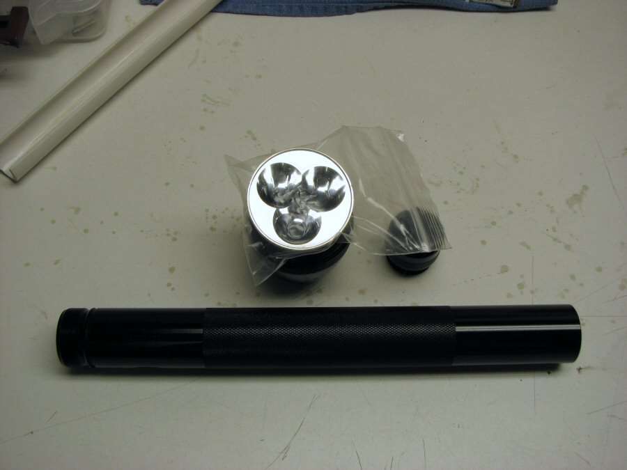
Good thing the head is the same ID as a "D" Maglite, or I couldn't have used the normal 50mm 3-up reflector.
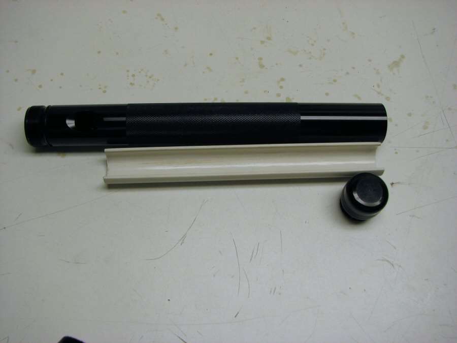
I first thought of using a plastic battery holder and I worked on making one out of PVC pipe, but I soon realized that the bottom battery would have to go into the tail cap, to have enough room for a fancy made parallel holder.
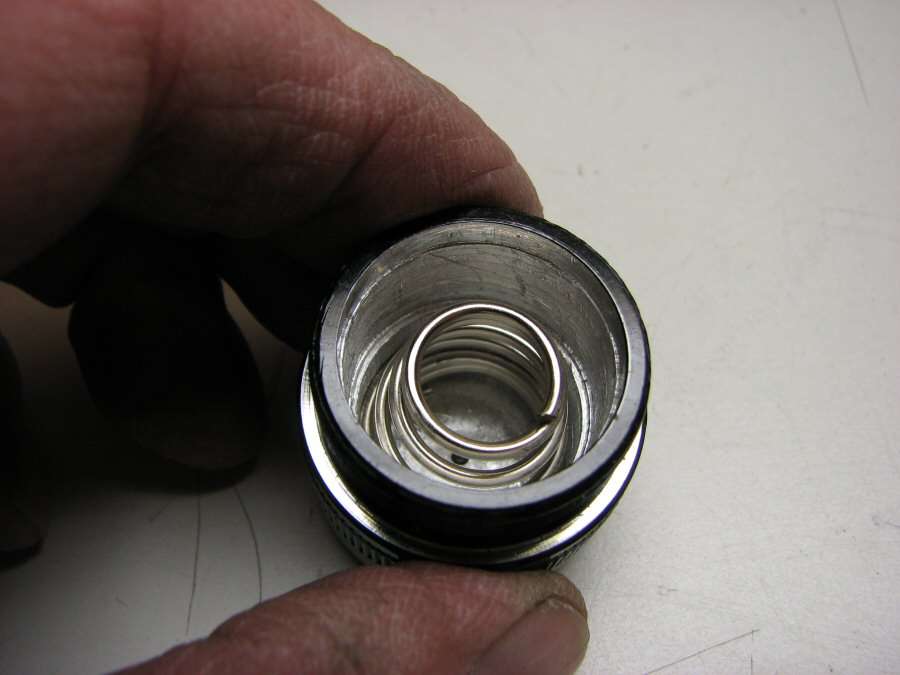
So, I bored out the tail cap, so a modified spring would fit in and I also bored it out so something else would fit in too.
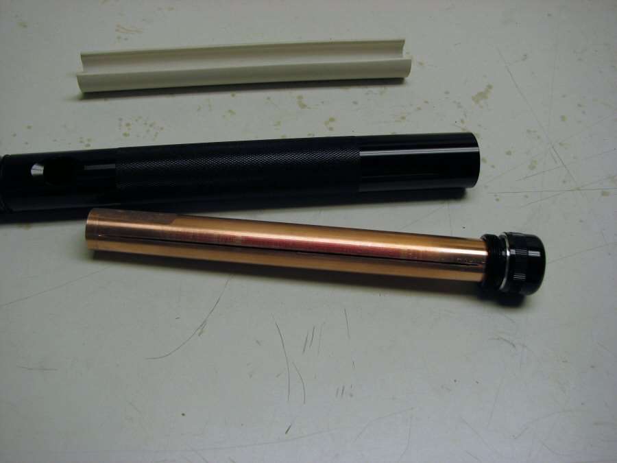
This is 3/4" Copper pipe. I am fitting it down into the tail cap and it will be the battery holder. It will be press fit and it will remain in the tail cap. When I take the tail cap off, the complete holder will come out with it.
I had to figure out a way to cut the pipe, so that I could remove the top half, for changing batteries. I settled on using Dremel cut off wheels in the drill press and made up a Rube Goldberg fixture, so I could cut straight lines down the sides of the pipe.
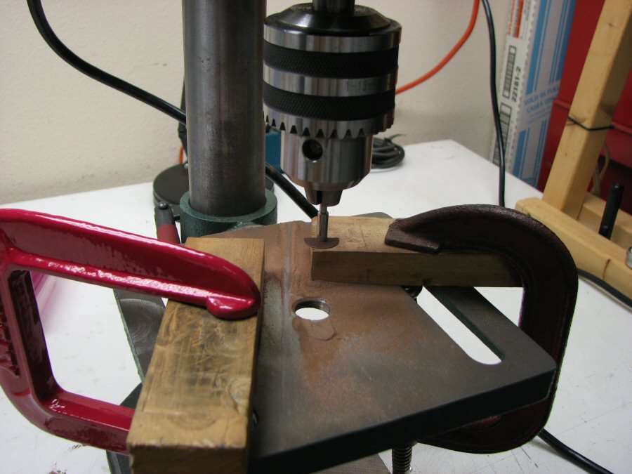
I went through a few cut off wheels doing this, but it did work out very well and it got the job done. Then I cut the ends with a hack saw and I left the ends full round, so they will add some stability.
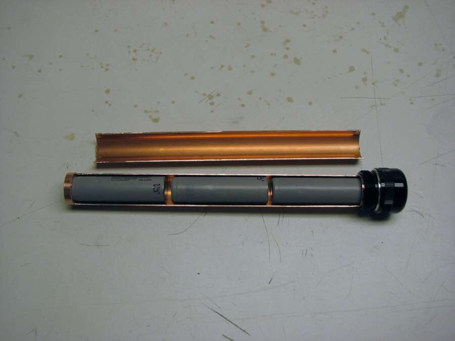
Now, I have to make the spacers between batteries, so that the positives all go forward and the negatives can just go to ground right against the copper pipe. The spacers will be made out of Copper and soldered to the pipe, with plastic spacers and small copper discs on those spacers, for the + terminals. It will make more sense when I get there and take some photos.
I will post more when I get more done....
---------------------------------------------------------------------------------------------------
12-13-13 OOOhh, Friday the 13th.
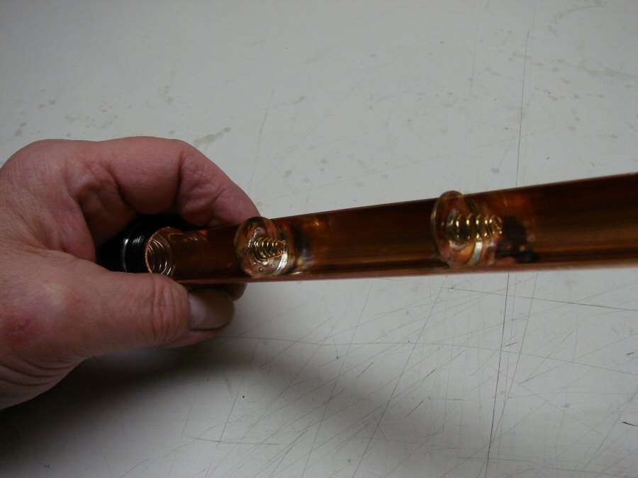
The negative contacts are in place.
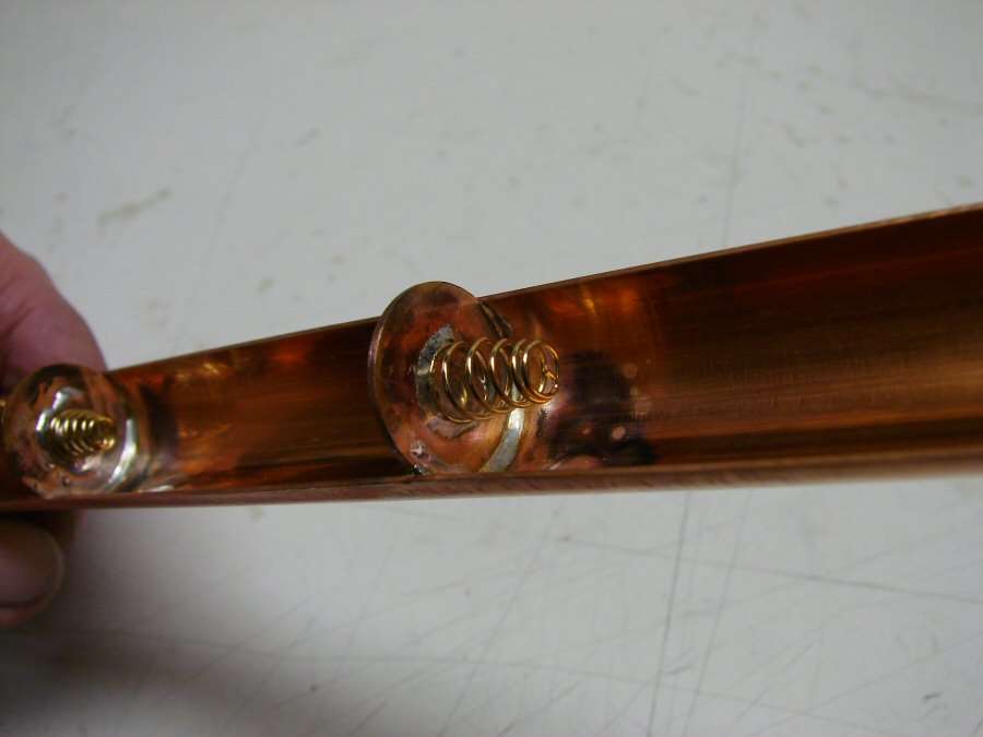
Closer view. I made a couple of copper discs out of some heavy copper plate and soldered them into the holder along with a couple springs. On the backside of each one will be a plastic washer, a smaller copper disc and wire for the positive contacts. I have to go to the hardware store to find some washers. I had none at the shop.
I also got the leds/stars reflowed and I got the heat sink made. I will take photos when it's more together.
---------------------------------------------------------------------------------------------------------
12-14-13
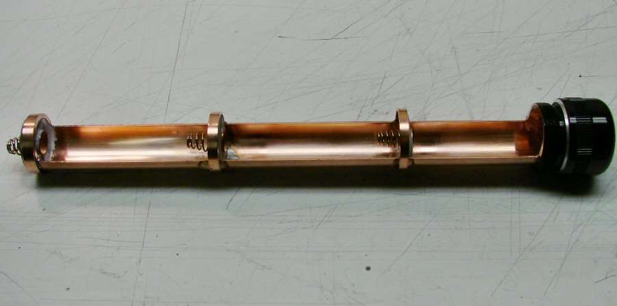
The Parallel holder is finally finished!
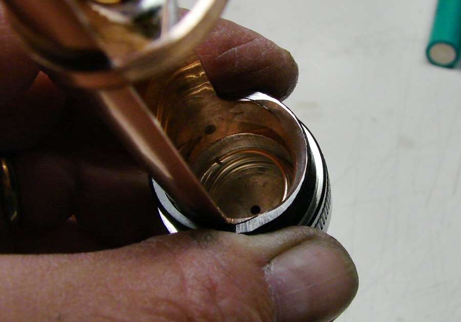
One of the problems was the fact that I had to sink the back battery down into the tail cap, to get all three of them in the space allotted. I had to do some dremel work here, to oval out the hole, so the battery could go in angled.
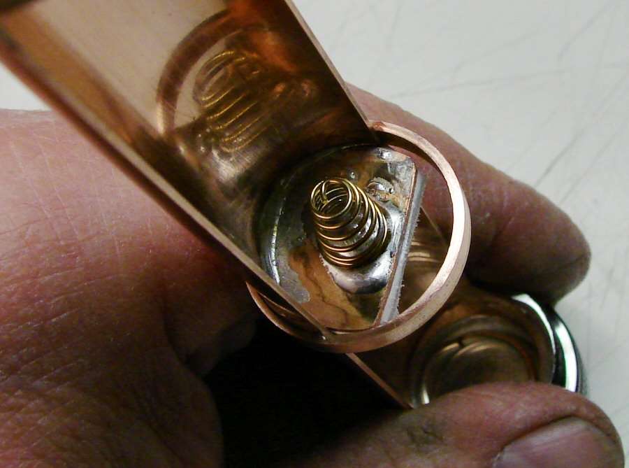
Also, I have to do some modding to the top end for that battery, so it would clear when putting it in at an angle.
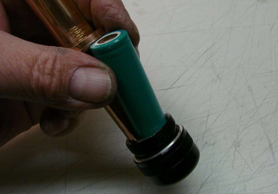
You can see what I mean here. It barely will go in, but it does go in and that's the point. A button top will not work in this light. It has to be an unprotected flat top.
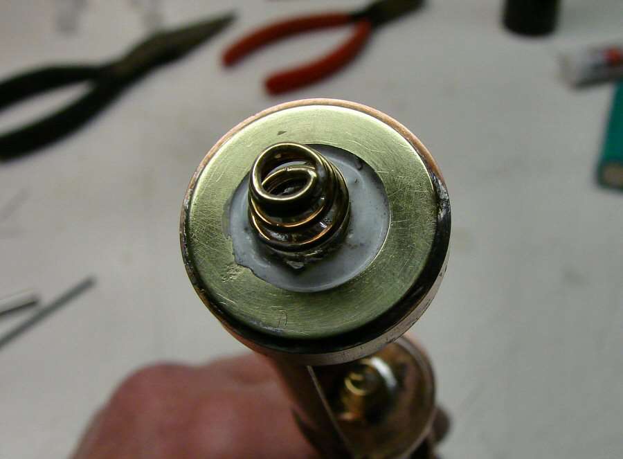
The top positive contact.
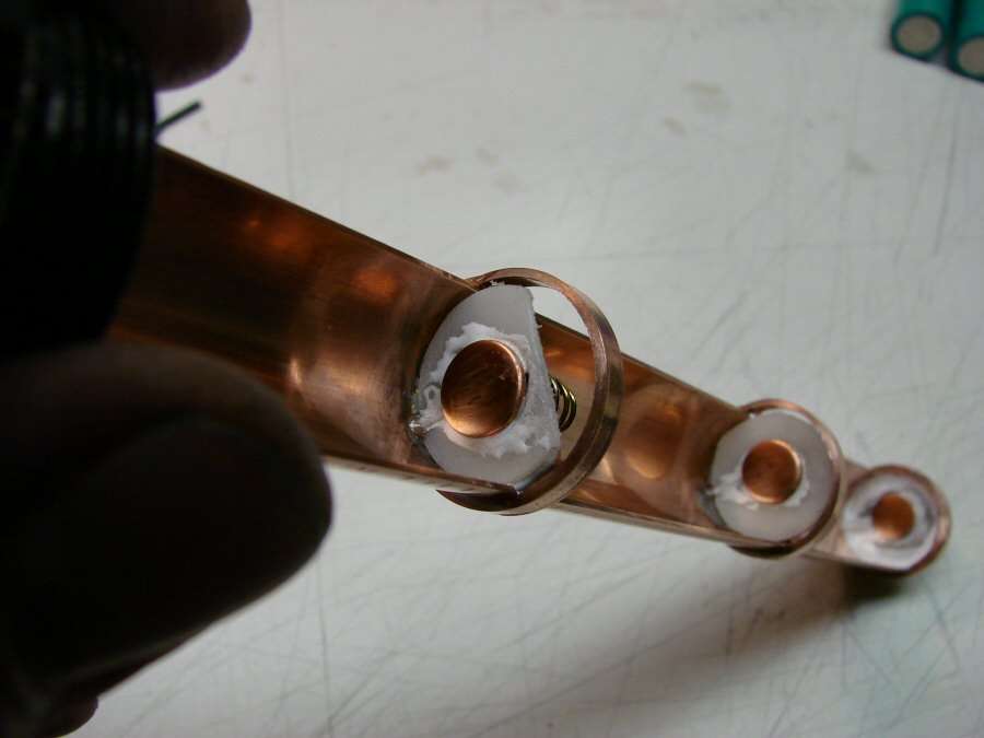
Here you can see the positive contacts on the underside of each set.
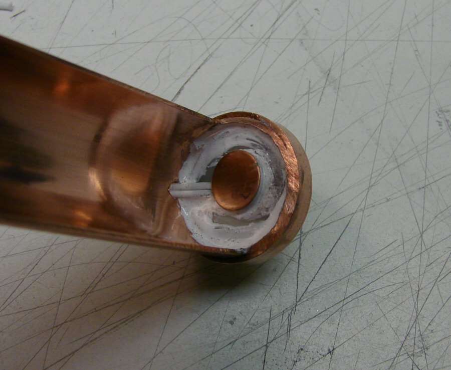
The underside of the top, where the wires from the other two come up in and join the top one.
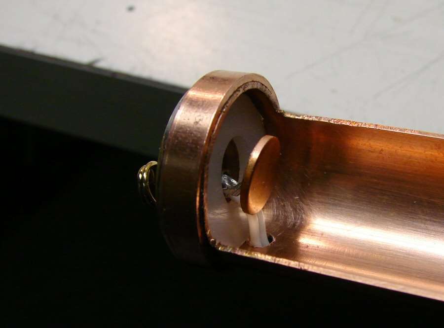
Before it was put together, you can see the wires that came up inside where all three got joined together.
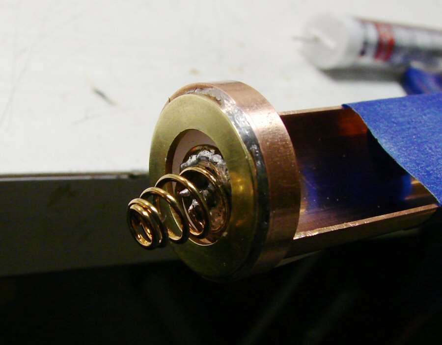
Before the upper positive spring was finished, you can see that the spring is on a copper disc and the three wires come up inside that disc. The disc sits on the plastic washer and I used a liberal amount of AA, so that there would be no contact between positive and negative.
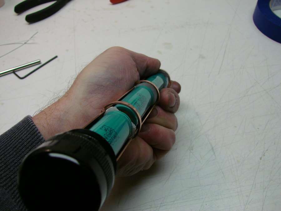
Everything was metered before trying the batteries one at a time and it all works!!
I did not know if it would really work and it was all done by trial and error, with a lot of hand fitting, but it's about the most robust holder I have ever made.
Now it's time to get back to the "normal" modding, like drivers and such...
-----------------------------------------------------------------------------------------------------
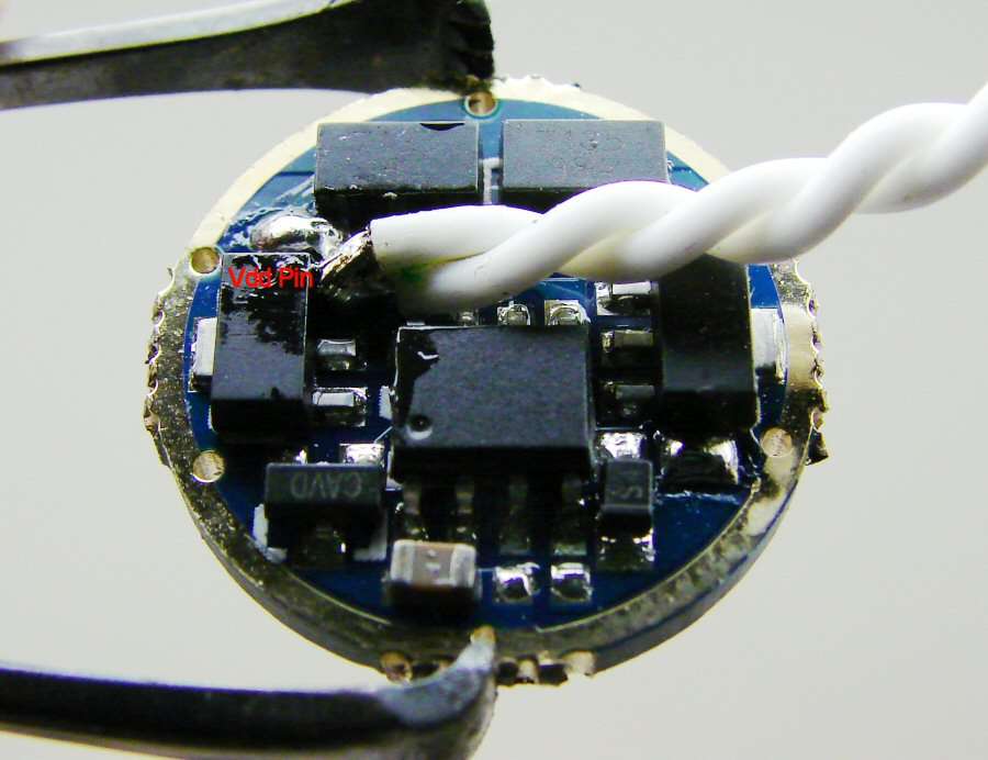
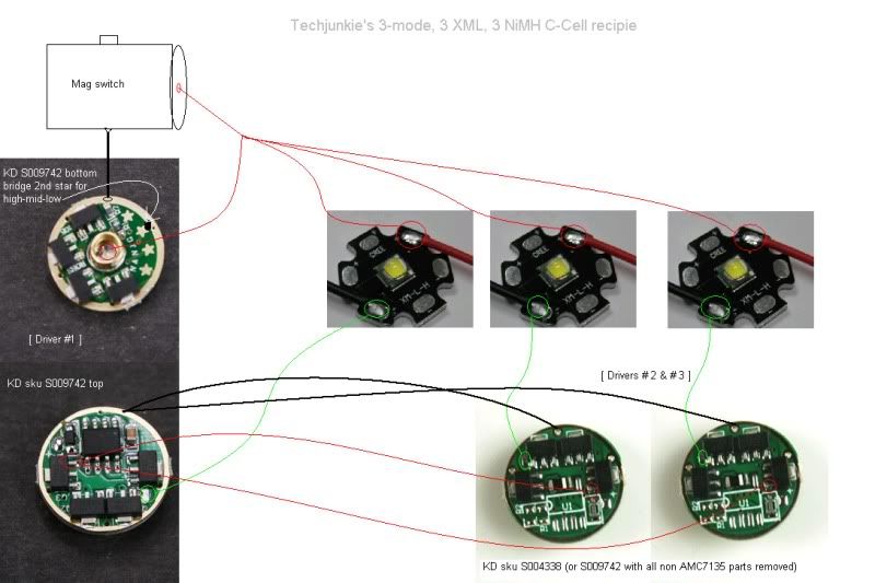
Master Driver has two wires soldered to one of the Vdd pins on any of the 7135 chips. I used this chip. but I could have used any of the other ones, as long as it is the Vdd pin. The pins are Vdd, Ground & Output.
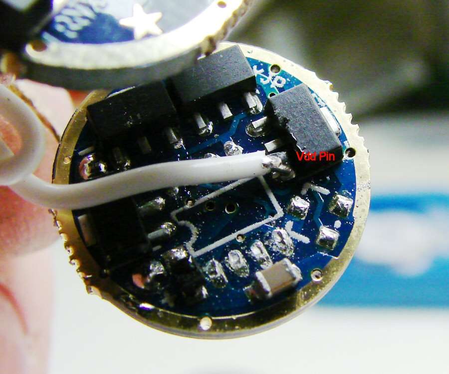
One of the slave drivers - One of the wires from the master driver is soldered to a Vdd pin. Does not matter which chip, any one as long as it is the Vdd pin.
The rest of the wiring is as follows;
- Positive goes straight to each led, (led plus), from your source and it also goes to the positive of the Master driver, right where the spring usually is.
- Negative, (Ground), goes to each of the three drivers. Usually soldered on the outer ring of the driver.
- led negative, (minus), from each driver goes to one led. Let me sat it another way, One led minus from a driver goes to one led and do that with each driver. Each driver controls the amperage to one led, independent of the other drivers, but because Vdd goes from the Master to the slaves, the Master controls the modes.
- I removed the controller from both of the slave drivers. There is another way. You can just cut the pin of the controller that is in the Vdd circuit on each slave, but I just cut all the pins and take the controller off. Either way it works.
- led Plus on all three drivers is not used, because we wired the plus side of each led, direct to the power source.
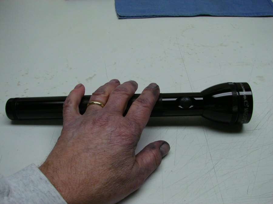
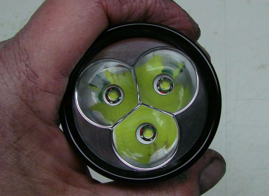
The last 3-up reflector I had and the derned thing was peeling! I had to sand off all the plate and then polish it. It came out good enough for a work light. I hate lousy plating...
Beam Shots
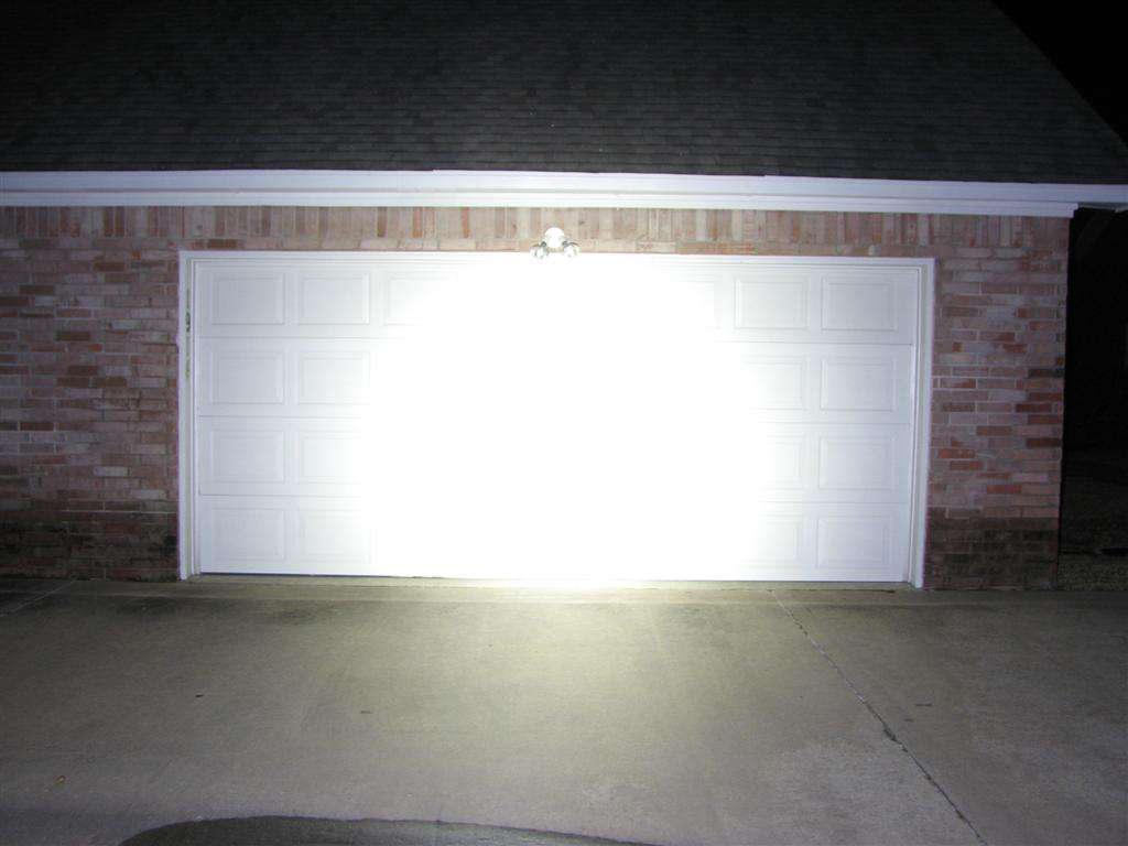
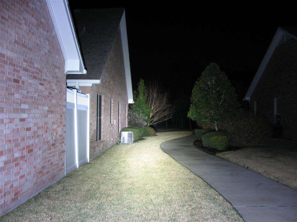
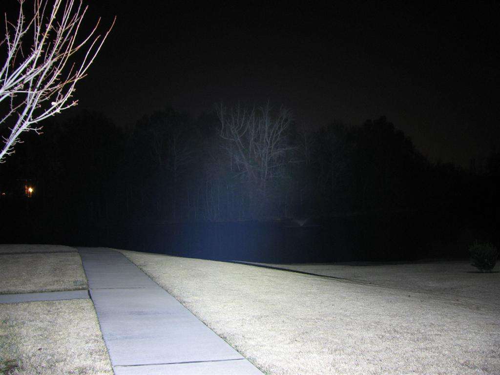
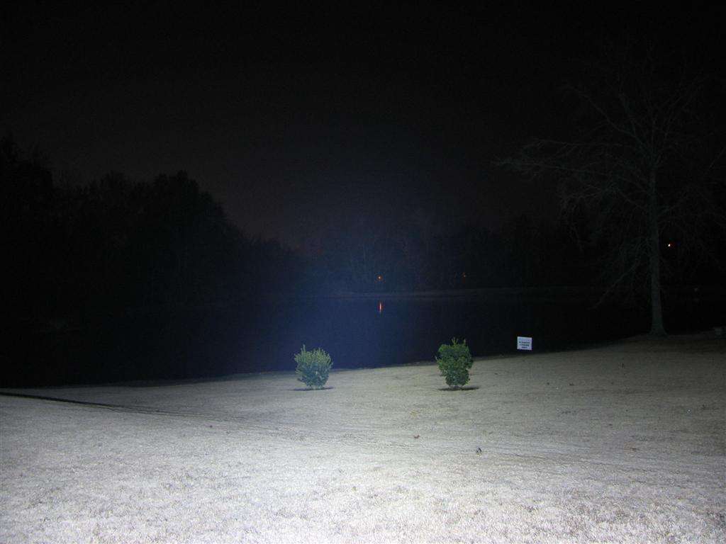
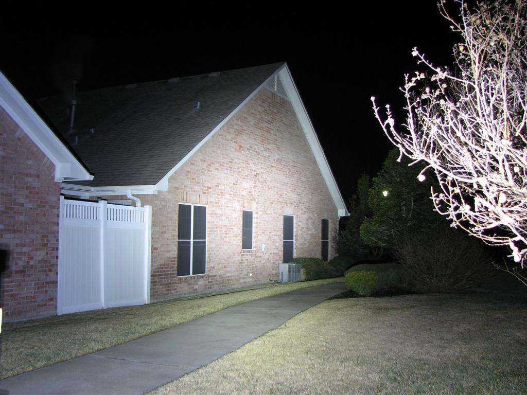
HIGH
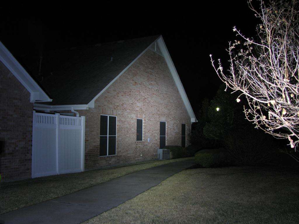
MEDIUM
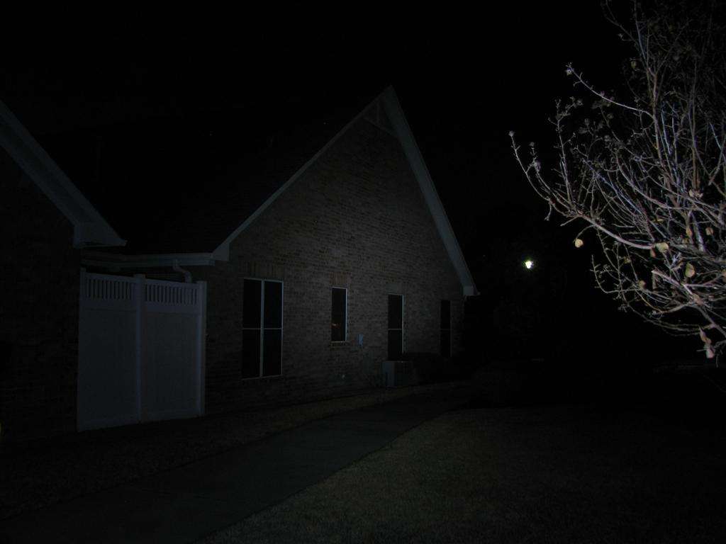
LOW
-----------------------------------------------------------------------
That's it. It works and it's bright enough for my needs. Most of the time I will have it on medium anyhow.
The drivers I used are the Fasttech generic 8x7135 drivers that go for cheap. Different controller, (I think), but the circuits work the same way. I added one chip to each one, since they were 2.8 amp drivers.
