10/31 Finished in post #227
Some numbers in post #3 and more pics in post #4
 Tail cap current measured at 4.3A with a 4.1V cell(Sanyo NCR 18650 BF)
Build posts have been daisy chained for continuous boredom
Placed a few orders and did some shopping at the salvage yard, bulk brass is $4/lb, copper $6/lb. didn’t buy any copper but also noticed they have big fat Alu rod stock(3-6” dia.) if anybody wants me to put a chunk in a medium flat rate box.
I’ll be using one end of the larger (7/8”) compression fitting for the male and female bezel fittings. From there back to the tube I’ll have to cobble together some fins on the outside and threading for the pill on the inside. P60 pills have 20 x 1.0mm threads and I was able to get a tap and die last year so I can make a threaded copper pill and tap it inside the fins. Figuring out how to keep all the fins centered will be tricky.
Does anyone have a few inches of Type K 3/4” copper? No local stores carry it. The ID of type K is just right for tapping 20 mm threads.
7/19 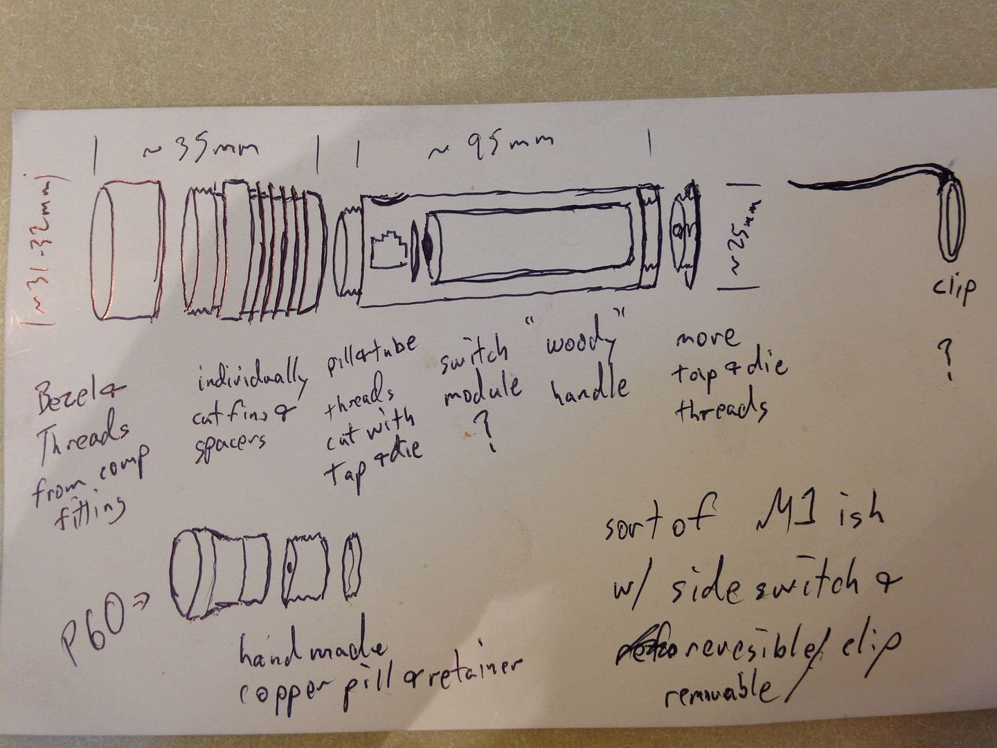
Later that same day …
I don’t have one of those builtlikeabattleship motorized hacksaws but I do have a reciprocating saw and that and a vice made this cut in short order. 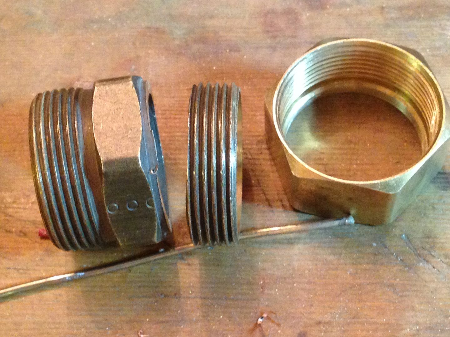
Then I screwed the threads and comp nut together and went to the drill press where I loaded up a hole saw with tape and 180 grit w/d. 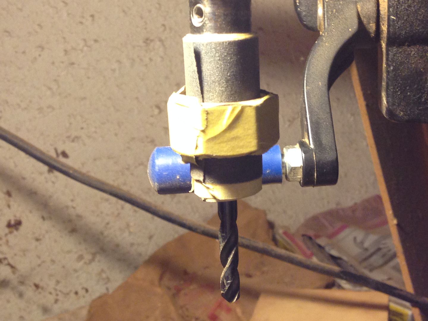 After a few hours and many additions of 2”tape(several feet in all in 1 1/4” increments).
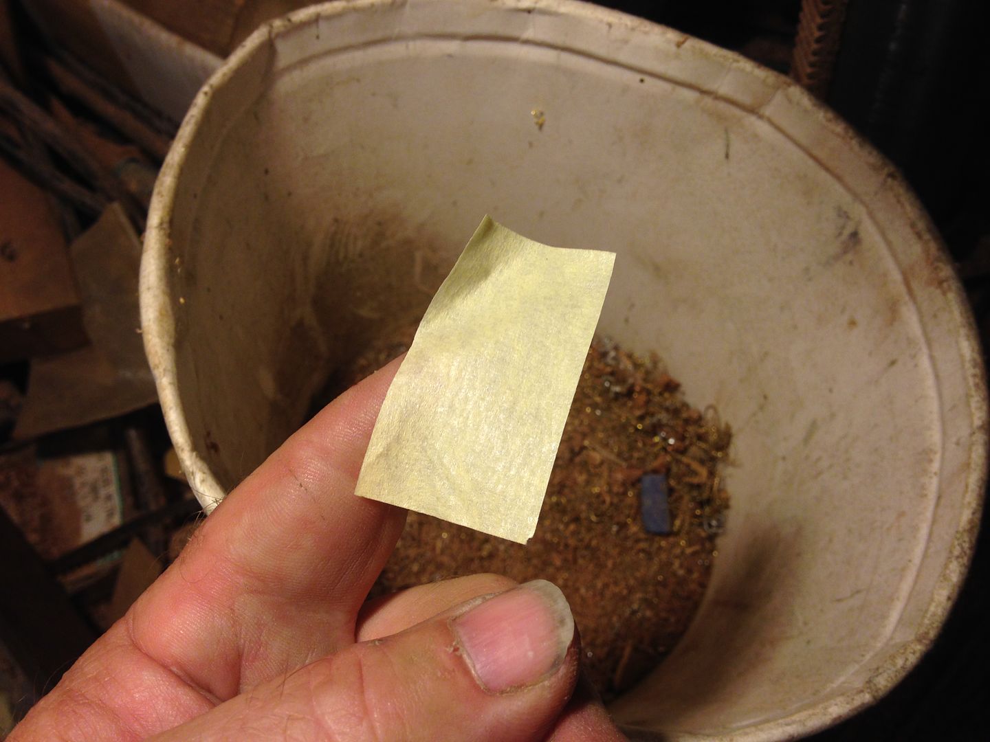
I had increased the ID from 22.4 mm to 25.5 mm lightening it considerably though the real reason for doing it has to do with how it all goes together. 
7/20
Now to start building back from the threads. I need a strip of brass cut, bent into a circle, and brazed into the threads. It needs to be very round and very snug.  After annealing it I rolled it around my 3/4” pipe sleeve stock which is ~24mm OD.
  Getting the ends to round is difficult but if you roll the strip inside another snug fitting tube it works pretty well.
  The ID of the thread piece was chosen partly to make this work out but only partly. I work with several different tube and pipe sizes that don’t all sleeve together tightly. In this case I was able to take advantage of the gap between the OD of 3/4” repair sleeve and the ID of 1” copper pipe to get a nice shape to the strip.
7/21
I lost some time after work as I had trouble finding my pieces. :rage: Once they were found I set about cleaning them up and brazing them together. All gooped up and wired.  Don’t touch, it’s hot!
  After a hot bath in Fuze Clean FS flux dissolver.
 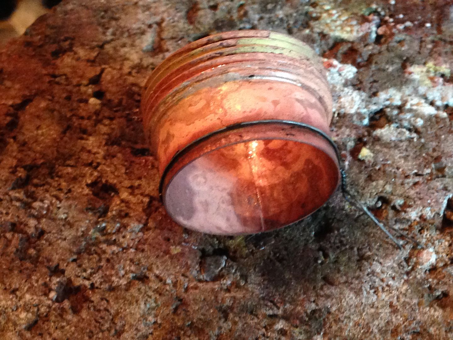 Heat brings copper to the surface of the brass but buffing removes it quickly enough.
 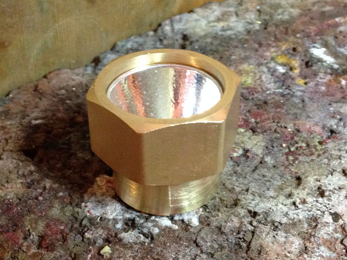 For what it’s worth, it ended up within .1mm of round, that’s ~4 thousandths. Still plenty of hand sanding to clean up the ragged saw cut end
 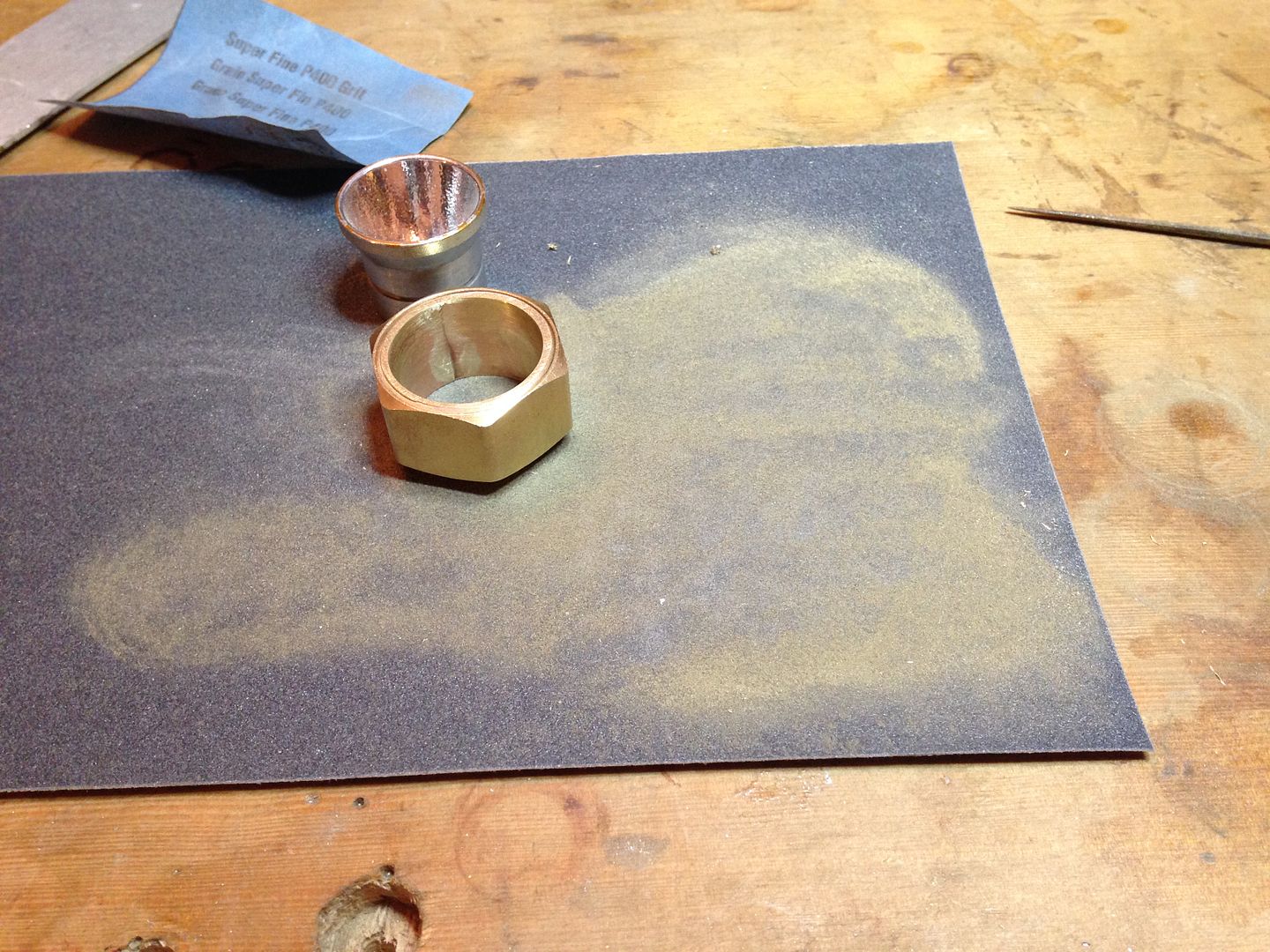 and to get it true on the ends.
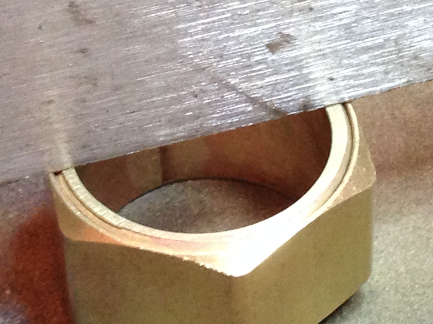
I’ll need to make more parts before the next assembly step.
7/22
Earlier this year I acquired some stuff from a member including a cigar tube and remembered it just in time to save me a bunch more reaming and grinding on the seat post I had been going to use. It is sealed at one end and has an o-ring at the other so to preserve those I cut a section for what I need from the middle 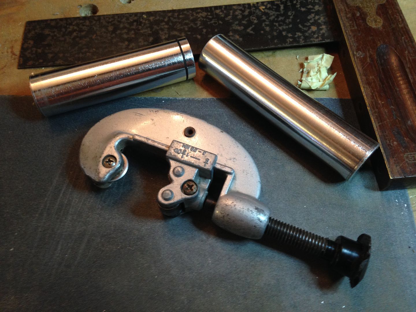 and sanded both ends square. I also marked the hole centers of some discs I’ll cut from a 1.5mm X 33 mm strip of aluminum.
 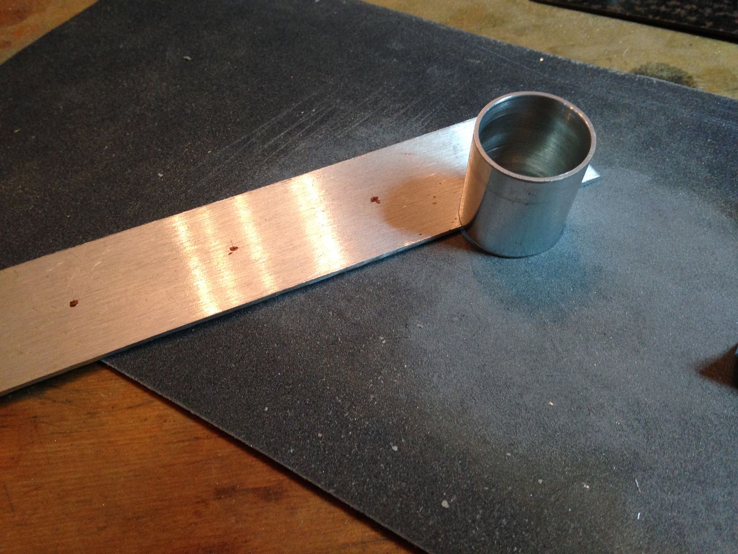 I’ll also need another piece of wood from that whateveritis root ball. This is what it looks like au naturel.
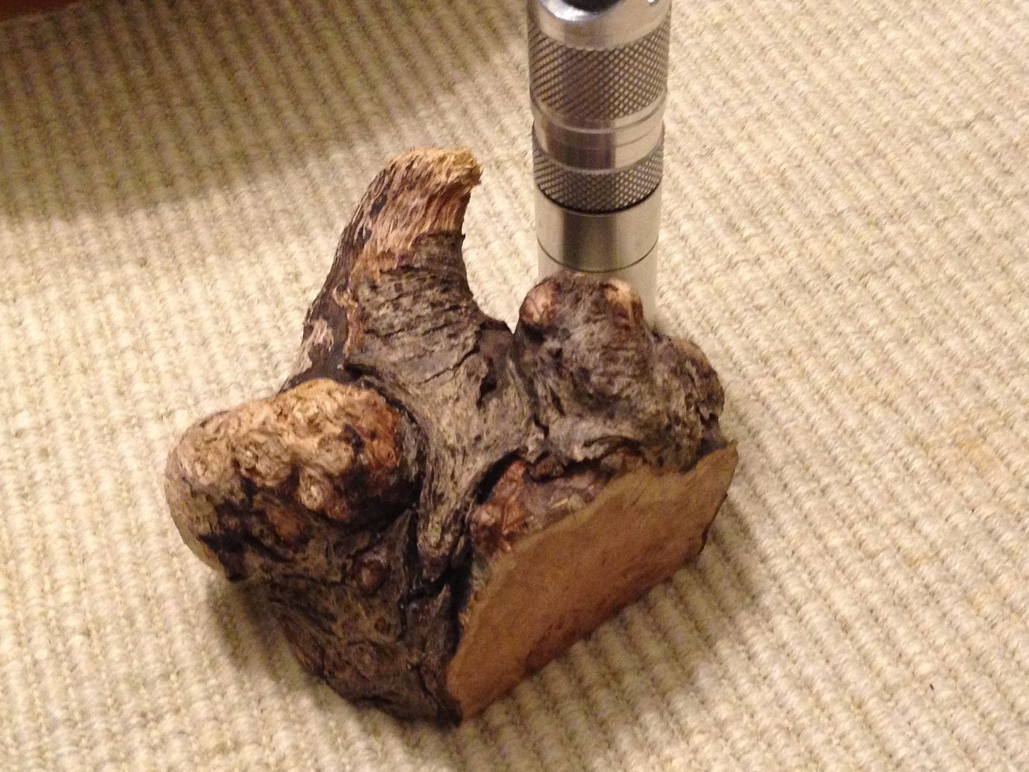
7/24
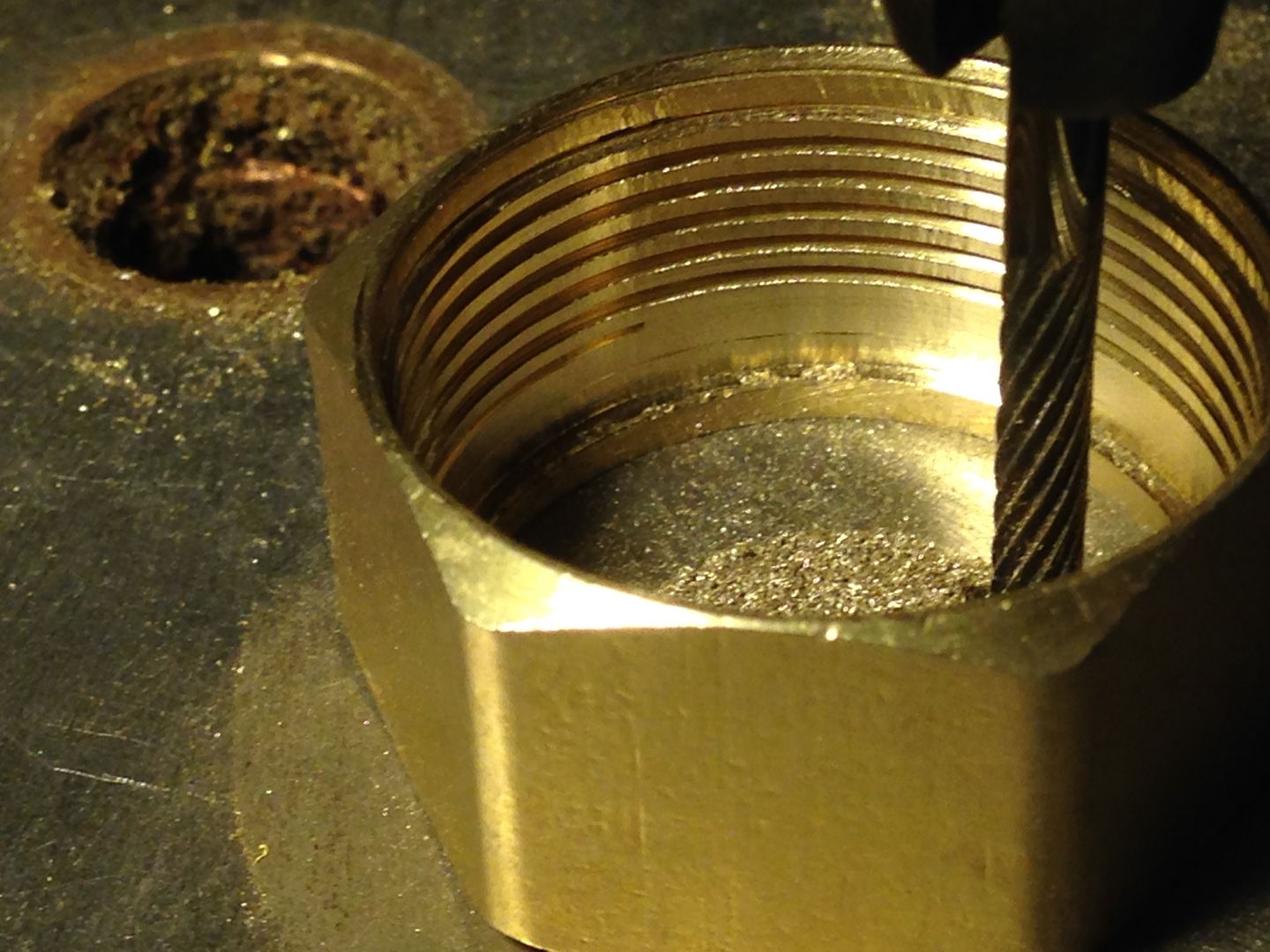
The bezel is too thick. I could sand it thinner from the outside but I’d rather cut from the inside instead with a Dremel bit. 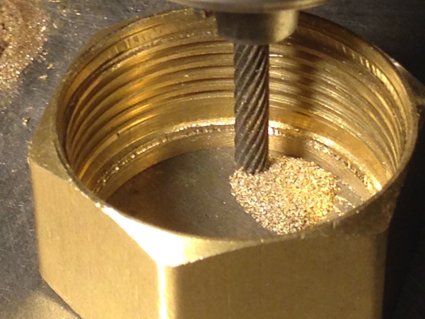
 I also cut an 11mm slab from the piece of burl just above.
 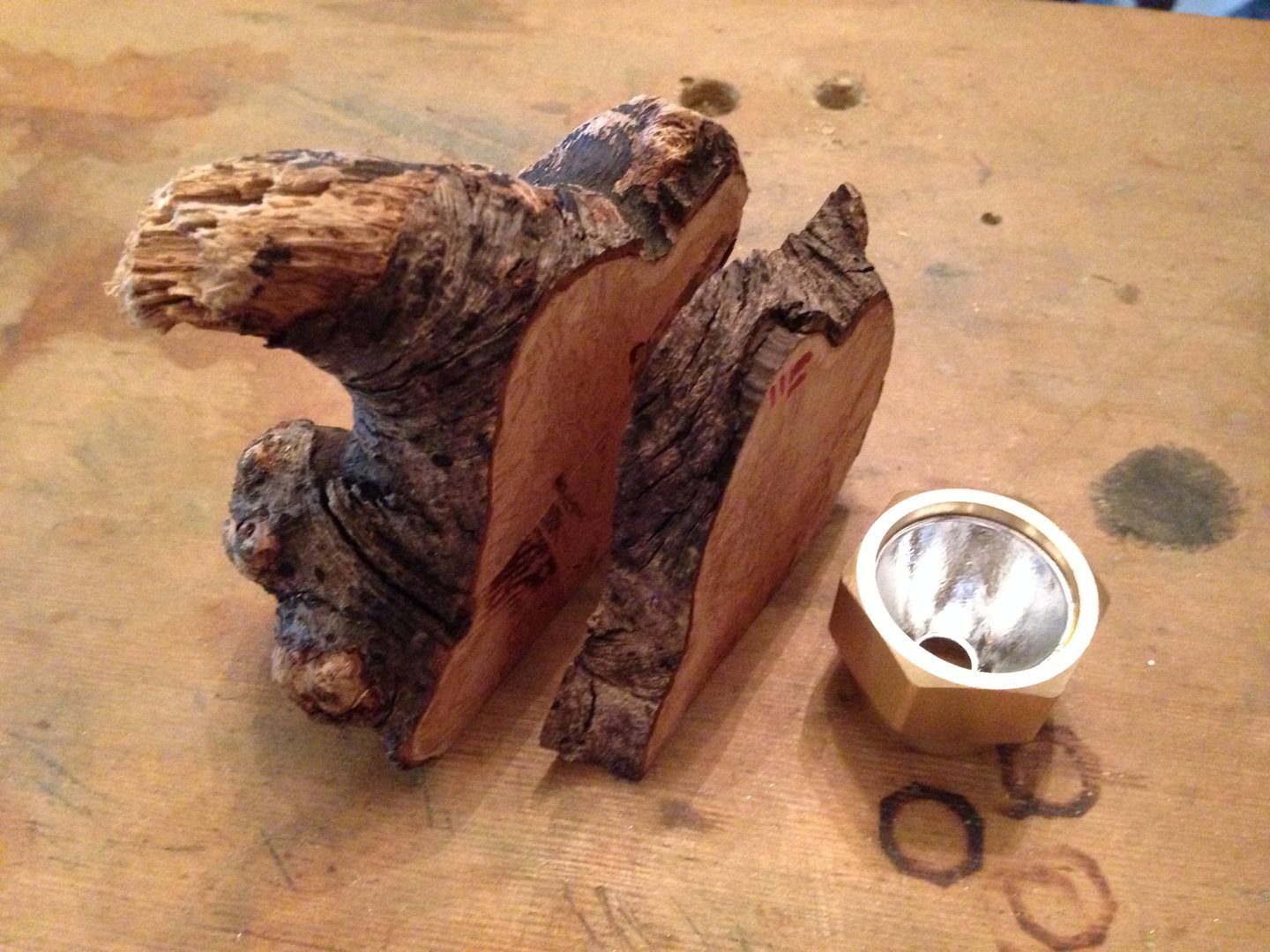 And after a bit of sanding saturated it with epoxy sealer to minimize chipping when it gets smaller.
 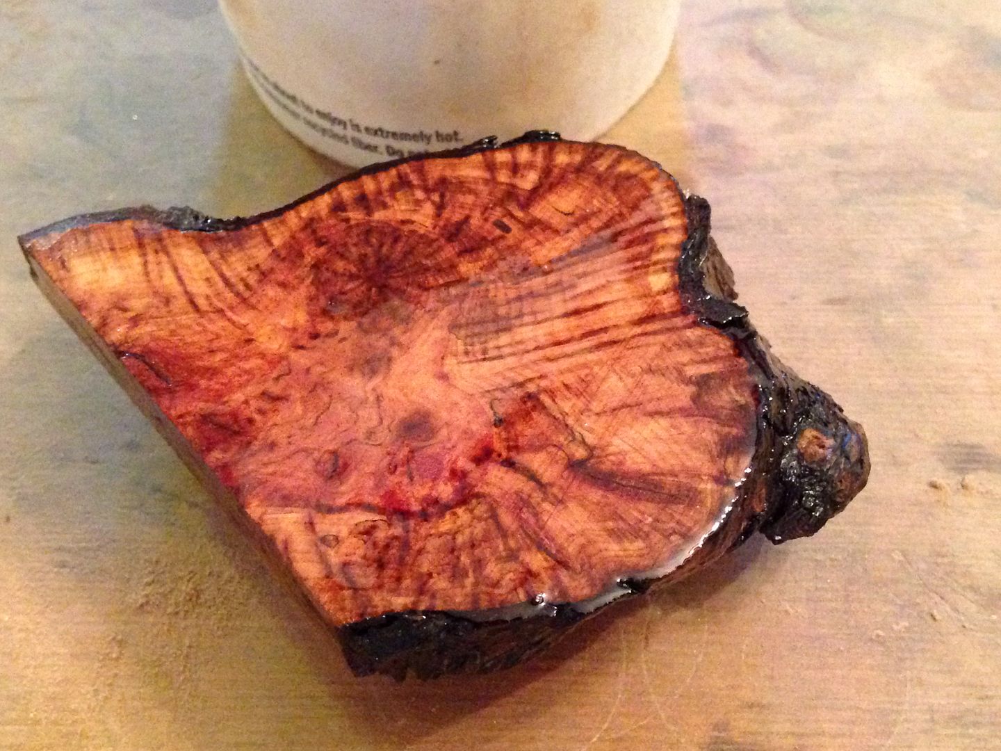 I won’t be able to work on this much for awhile so it will have plenty of time to cure properly.
7/26
Just time enough today to set up and punch out a few loose fins. Oops, one slipped!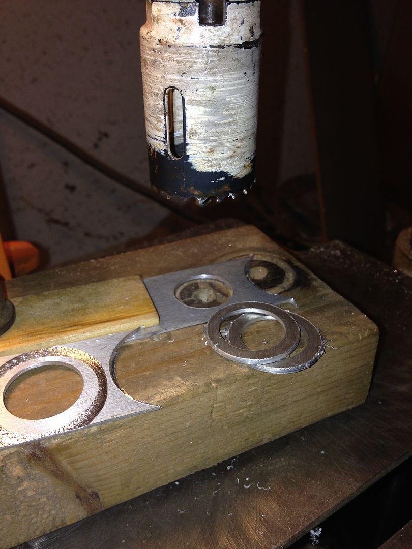 I’ll need to cob up a jig for the spacer rings as I want them to end up the same 1.5mm thickness as the disc fins. For now I ended with taking the plunge and mistreating some wood in a similar fashion. I learned the trick of gluing a small piece to a larger one separated by paper to allow for clamping the small piece way back in 8th grade wood shop.
  Tune back in this weekend to see whether it survived two separate hole saw attacks.
7/27
Can’t do any physical work on the light but need to figure out the details of moving the switch from B- to B+. To that end I’ve made a rough sketch to get started and improve the picture in my head.  The button cover has a rectangular apron bent into a curve to fit inside/outside a tube but I need to create the space for it in the layers of brass tubing, hopefully under the wood and outside the innermost tube that is the switch module. I might need to add another layer or two of tube to account for it since it would be stronger to have just the button hole itself in the outer brass layer where the wood is dimpled around the button.
7/30
I started by squaring up both ends and marking and knifing a start in each. I’ve intentionally marked slightly off center to maximize clean length.  Then I used a small bit to get started, once in awhile allowing the wood to spin slowly and adjusting in the direction of the wobble to correct it. Perfection isn’t likely nor necessary at this point but good is definitely better than bad.
  Then I switched to a 1/8” bit and after again noting the high point off the wobble angled slightly in that direction. This bit is still too short to get all the way through but I have another for that.
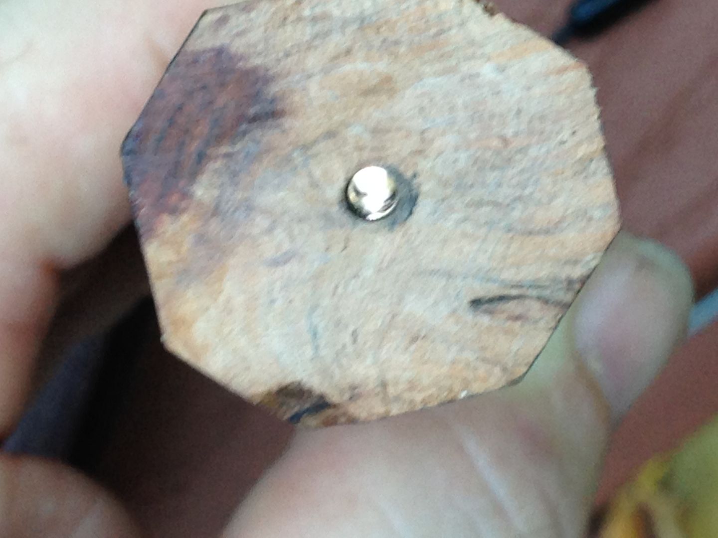
 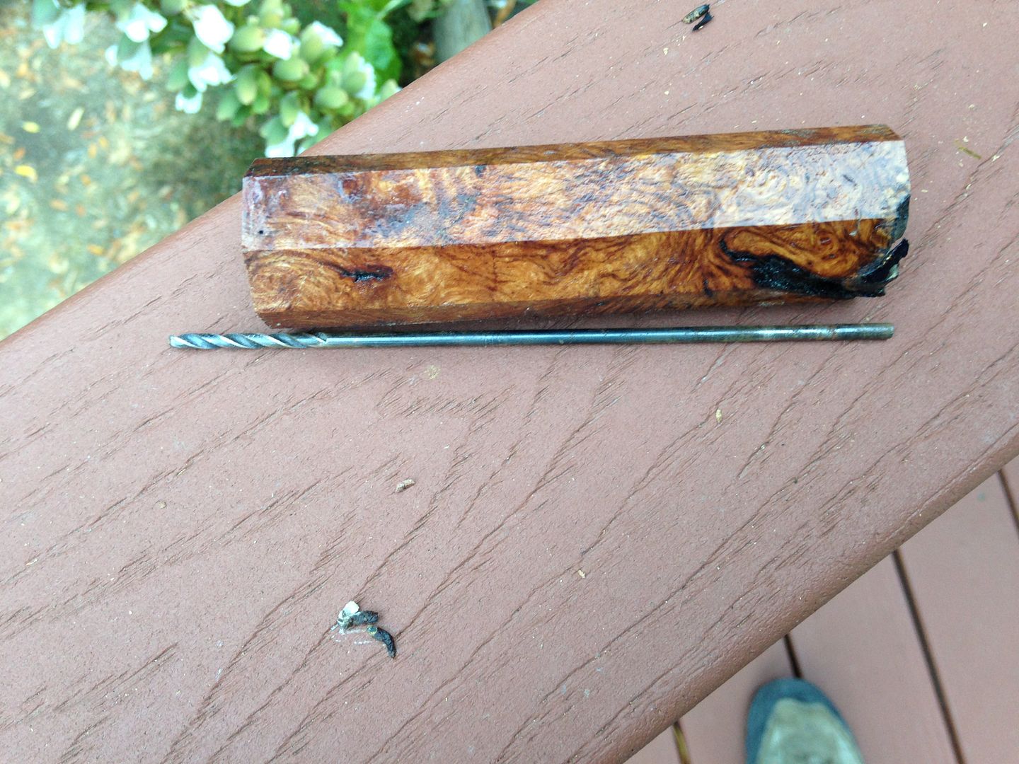 Bingo.
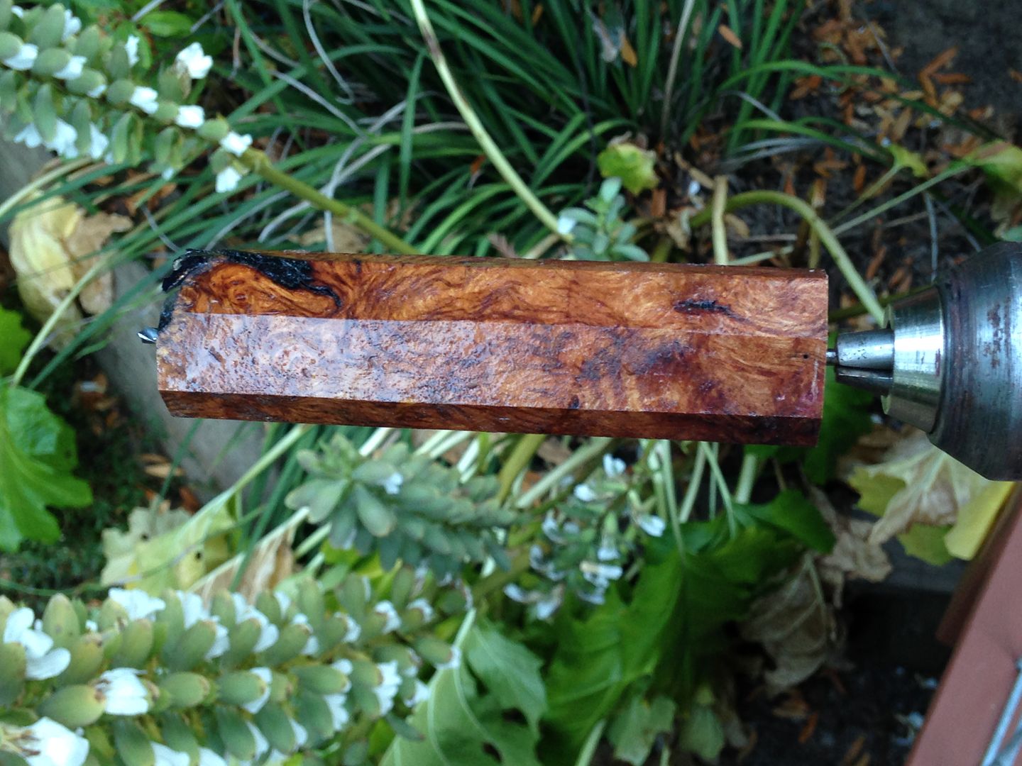
 From here until I hit 1/2” or so it’s just a matter of stepping up the bit size gradually so as not to explode the burl with pressure from within. Here it is at 3/8.
 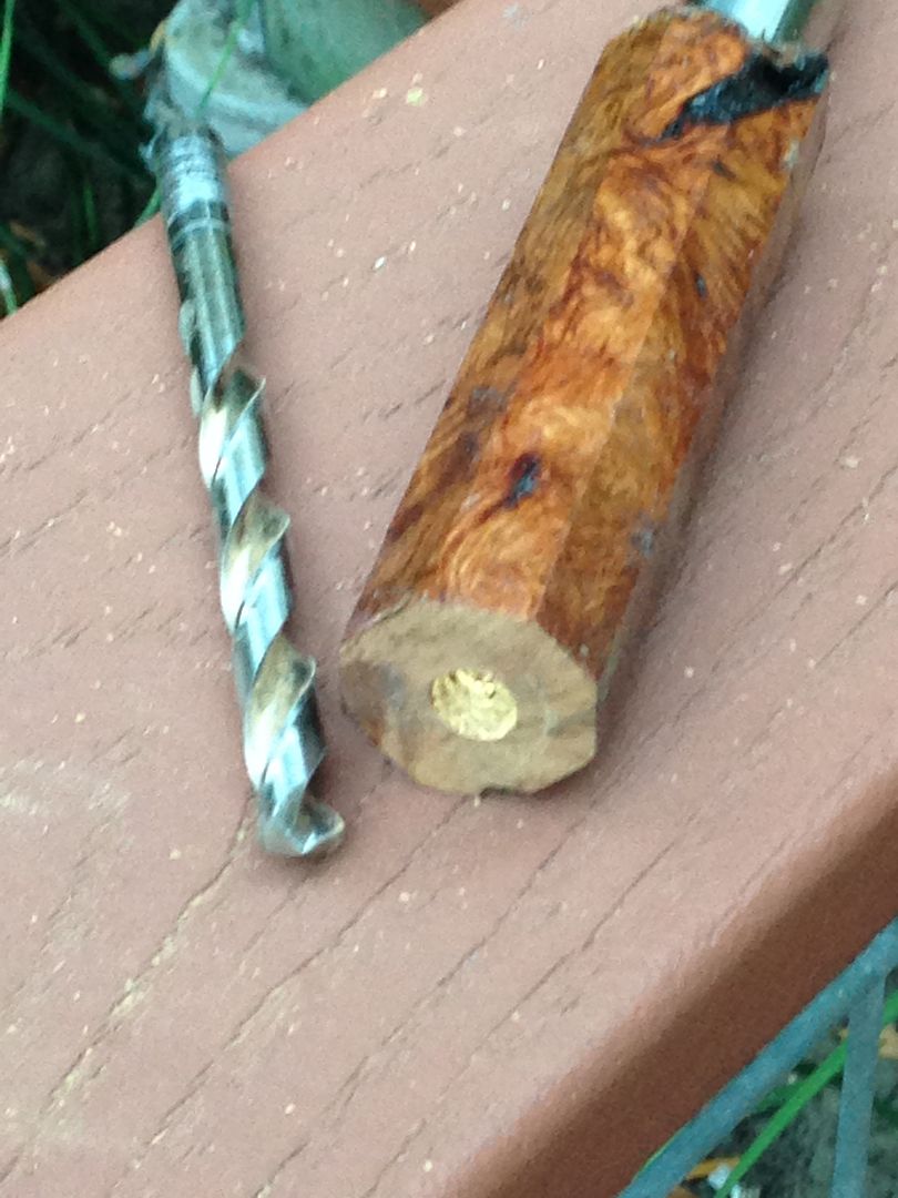 Once I reach that point I’ll switch to sandpaper wrapped spindles to increase the ID with even less outward pressure. When I get to 5/8” or so I’ll start saturating the wood with epoxy sealer from inside the tube to strengthen it for the next session. I won’t turn the outside of it until the brass sleeve tube is ready to be epoxied into it to act as a structural core.
Link to continuation
 Grain matched
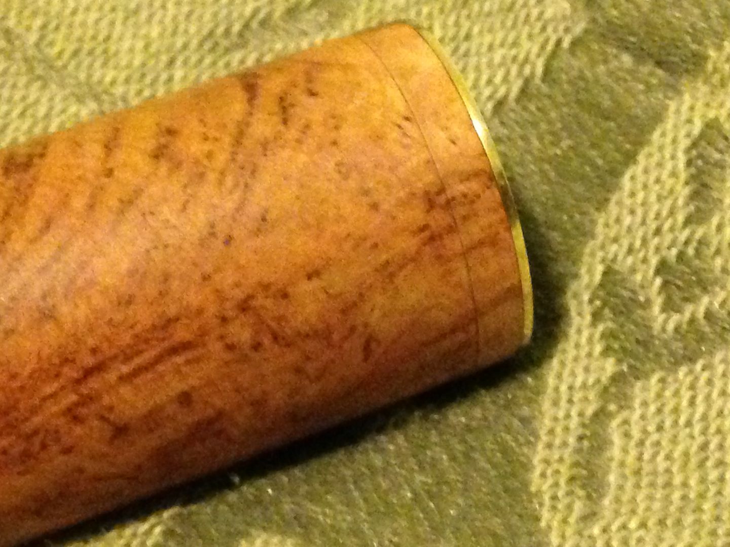
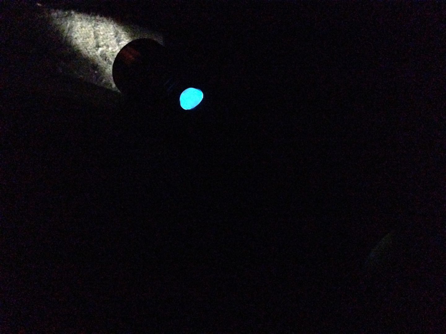
 Trit lit cabochon is actually quite visible to dark adjusted eyes though not in any way bright.
 Looks great. Look forward to the finished product.