http://www.ebay.com/itm/161104795308
Chinavally replied that this version is confirmed using the JB driver. However I don’t think he can confirm if it is XM-L2 or L.
http://www.ebay.com/itm/161104795308
Chinavally replied that this version is confirmed using the JB driver. However I don’t think he can confirm if it is XM-L2 or L.
Like has been said though, the aluminum star is the main throttle to performance that won’t destroy the emitters. Buy an assortment of smd resistors and play around with a dmm and ohm’s law to figure out what resistance you need to put in there so each emitter gets maybe 2-3 amps, which is okay for an aluminum-sunk emitter, and at that current level the difference between XM-L and XM-L2 is not noticable.
Or, you can buy some copper stars and reflow the emitters onto them. But then you’re three dollars per star away from buying XM-L2’s pre-flowed onto those stars. So really it’s a relatively small matter if you need to upgrade to –2’s given the cost you’ll already be investing.
I like the copper plate underneath the aluminum mod, it seems easy enough for a newbie like me to mod.
Reflowing the original emitters to new sinkpads are quite a large task, and I dont think I can do it without damaging the existing emitter.
I think adding the copper plate give it more surface area for the heat to spread. But not sure how effective that would be.
I think doing the wires and resistors for me would be first and I will see what else I can do.
Clearly you do not understand what Comfychair was getting at with his posts.
The copper plate WILL DO NOTHING as long as you’re using the original aluminum star. If you do the wires and resistor mod you will cook the emitters to death. Go back and re-read comfy’s posts before deciding on the mods you’re going to do.
With the copper MCPCBs the LED is soldered directly to the copper base. With the aluminum MCPCBs, since you can't solder to aluminum, there has to be a thin layer of copper over the aluminum, and there has to be a thin layer of insulation between the thin copper on top and the thicker aluminum on the bottom, to prevent the whole thing from shorting out. Insulation is a Bad Thing to stick in the middle of a thing that's supposed to transfer quite a lot of heat. This insulation is made into the middle of the aluminum board like a multilayer sandwich. Any heat from the LED has to go through all those layers before it ever gets to the copper shim you stick underneath, so if the heat can't get there in the first place it doesn't really matter what it's sitting on.
You don't need to do any LED re-soldering, XML2s of various tints are readily available already mounted on 16mm copper MCPCBs. There's no guarantee you'll get a light with XML2s in it anyway.
Gotcha.
So what is the first thing I should do when I get the light?
I bought the black 4x version, cause Chinavally replied saying its a JB driver and I didnt want a champane 3x.

It depends entirely on how much you want to invest. If you want to bypass the resistors and direct-drive this light you will need four good-quality, low resistance cells. They don’t need to be brand-new Samsung 20R’s as a 9-10 amp draw spread over four cells is reasonable and laptop-pulls, provided they are genuine, will yield suitable fodder.
Secondly, you will need to put the emitters on copper. It will be $16 to put the emitters on copper if you reflow them yourself. You may as well spend $28 and upgrade to XM-L2s at the same time.
Thirdly, you must know that this turns the light into a battery-burner that will get too hot to hold in a matter of minutes, and you will spend most of the time using it on the ‘low’ setting.
The JB driver with the resistors bypassed, 3x XML2, and running on medium is right around 50% more light than a good unmodded 3x SRK with the old 3-toroid driver puts out on high.
Thanks for the tips guys, can’t wait for the flashlight to arrive!
It’s too bad we don’t have FLIR unit to measure or see what the outcome is after adding the copper plate underneath the aluminum one…
I bet FLIR applications would be a good thing for the flashlight modding community as it can show heat signatures where we can improve our lights…
Was thinking of buying the wallbuy’s samsung 18650 since I don’t have any 18650 laying around the current moment.
Hi comfychair and oldlumen,
I just got this flashlight here:
I was wondering if I upgrade the wires driving the emitter and driver to something like this,
Will it be okay or will I fry the emitter/driver?
Thanks in advance!
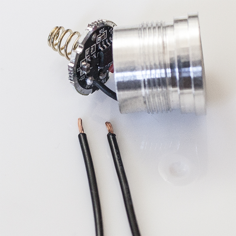
Firstly, that looks like a simple low-current driver, an amp or so my guess. At that low a current level the wires are an almost negligible impedance to output. Either way, automotive/household 12ga wire is not a good choice for flashlights as its just too big and waaaay overkill.
That is a 20ga copper speaker wire pulled from some spare wires I had laying around in the basement.
I couldn’t get access to the star since there’s a white plastic piece glued down to the star. Thinking if I should change up the wires still…
There's nothing to be gained by just changing the wires. Besides, a single LED isn't comparable to 3 LEDs in parallel, all 3 being fed by only two wires. That JB driver is capable of over 15 amps depending on which cells you use. Totally different animals.
Ah I know what you mean, reminds me of those glass fuses how 2A is very very hairline thin.
I won’t bother with swapping the wires, I’ll stick to the original ones. Thanks!
Can’t wait for my Securitylng. Hehehe :bigsmile:
I’ve got my light, how do you dissemble this thing to get to the driver?
use needle nose pliers in the divots in the ring around the button. Unscrew it so the button comes out, the momentary switch underneath and its pcb may be pulled out. Using a chopstick or some other rigid rod, pop the driver out from the inside.
In addition to what TGT said, you may want to use the search function. Include the term SRK or Skyray King as that is essentially the same light.
Hi Comfychair, I moved the wire here.
Should I remove the resistors or just keep them?
Thanks in advance!
This worked perfectly! Thanks!