Here is something I’ve been slowly working on recently: a tool to flash Sonix MCUs in recent Convoy drivers.
As you probably know, recent Convoy drivers contain SN8F57xx microcontrollers instead of the old ATtiny13. The only way to program them used to be a 50$ proprietary SN-Link programmer. So I bought one and decided to reverse engineer it to replace with cheaper hardware. Turns out the programming protocol is just single-duplex UART, and you can use a cheap USB-UART dongle! The only catch is that the chip would only listen for a few milliseconds after reset, so a dongle with exposed RTS or DTR signals is recommended for a hardware reset circuit.
But then, it turned out that a lot of Convoy drivers don’t have programming pads. And most of them have their programming pin (SWAT) attached to an RC circuit that interferes with UART signal, so you can’t really program them in-circuit. Here are my research results:
5A 12-group linear driver for S2+: has programming pad, has RC circuit
5A buck driver for S2+: no programming pad, has RC circuit
6A driver for S21E: no programming pad, has RC circuit
6A driver for M26D: no programming pad, has RC circuit
1.5A dual-fuel 12-group driver for T3: no programming pad, has RC circuit
1.5A dual-fuel 4-group driver for T3: no programming pad, has RC circuit
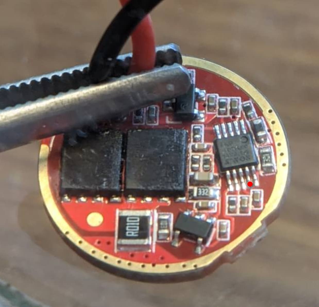
5A dual-fuel driver for T6: has programming pad, no RC circuit
So, the only driver so far that is confirmed to be easily programmable is the 5A dual-fuel driver: it has an exposed programming pad and nothing is interfering with the signal. Sadly, the drivers are read-protected, so the only way to have custom firmware on them is to reverse-engineer the hardware and write firmware from scratch. But it’s a complex driver with both boost and buck circuits and a lot of tiny parts, so the idea of reverse-engineering it is giving me shivers
I’ve also ordered a couple of simple 7135 drivers to see whether they can be programmed in-circuit as well. I’ll probably try starting with them first.
So here is a question to the community: are you interested in custom firmware for T6 Convoy drivers? And if someone has already tried to reverse-engineer the driver, I would be very happy to hear about that.
This is very lit, very well done. I am v interested in new firmware for Convoy drivers. Even if it’s just the 5A T6 driver it’s still 17mm and so fits in lots of other hosts. The simple addition of a medium press to go backwards (and to turbo from moonlight) as found in Bistro or the BLF A6 firmware is sorely lacking, in my view, from the Convoy UI.
Having the ability to flash Bistro onto regularly available, reasonably priced, reasonably efficient drivers would be a real luxury.
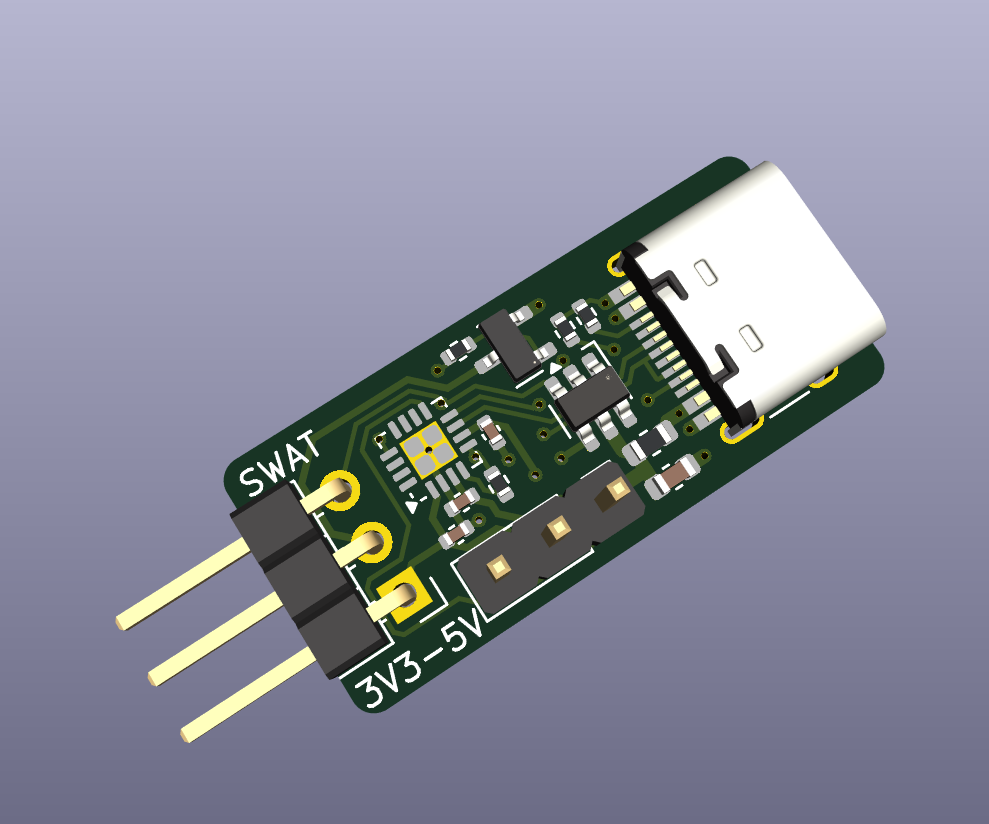
In case the firmware development for Sonix Convoys gets anywhere, I just clicked together a small dedicated programmer based on your writeup that directly outputs VIO (selectable between 5V and 3.3V), GND and SWAT. ESD protection on USB datalines, VBUS, SWAT and VIO too, because why not. Wonder if I should add a fuse, too…
EDIT: Just added a fuse. There was still space
If people are interested I will push it to github, together with the files to order them at jlcpcb for cheap.
I’ve contemplated making something similar once the software part is sorted out, but you were much, much faster! Would definitely try to build one if you publish Gerber files.
Regarding the T4 driver – nice find! I’m pretty confident the pads are connected, but the question is whether there is an RC circuit or not. Sadly it’s hard to judge by the official photos, because the MCU is sandwiched deep between the two boards. I’m not sure why Convoy engineer even bothered with programming pads on the 5A linear driver, since it can’t really be programmed with that capacitor soldered in.
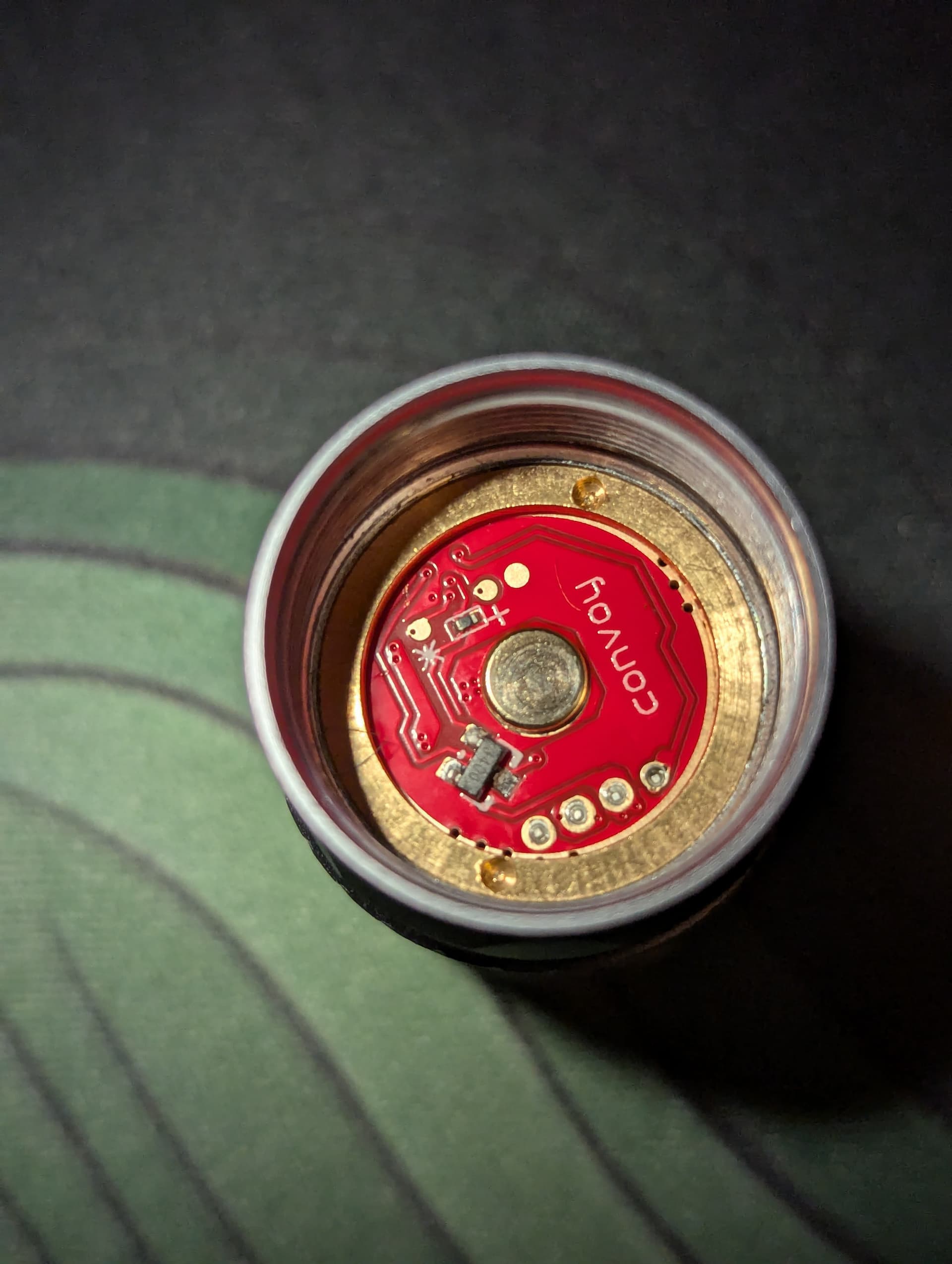
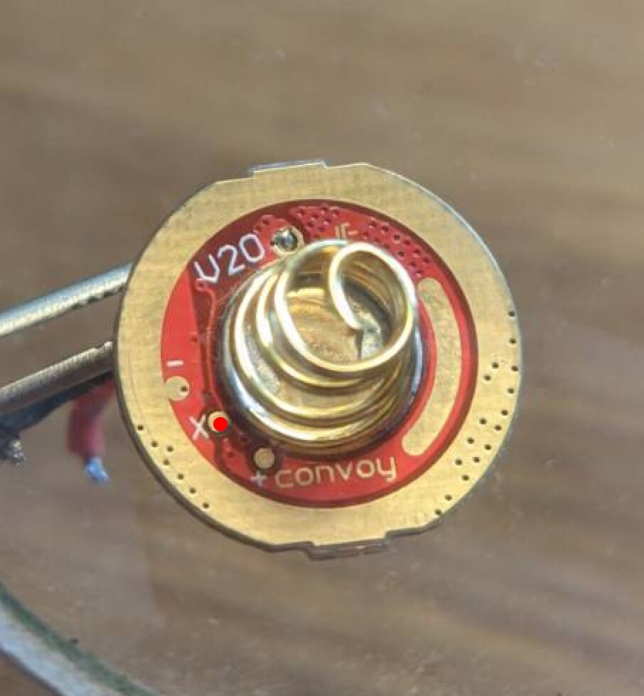
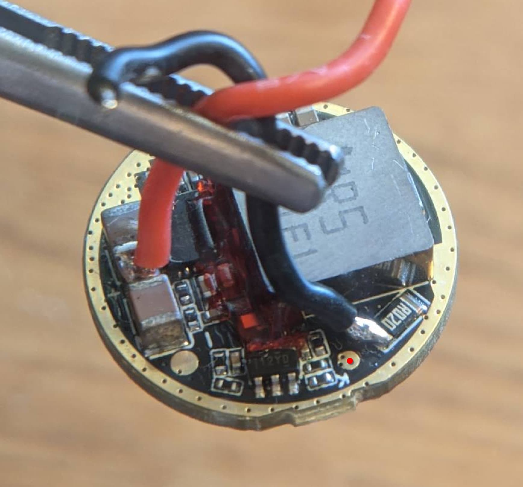
I’ve had a little look at the spare drivers I’ve got and I think I’ve found two that fit the bill. I just had a little poke around with the multimeter and presumably if the programming pin isn’t connected to any resistors or capacitors nearby then its fine? Connected areas have the little red dot
Programming pad, no RC circuit:
3V 6A 20mm linear driver (V20 on PCB)
I’m not 100% sure what it does but I’m guessing this is the RC circuit previously mentioned.
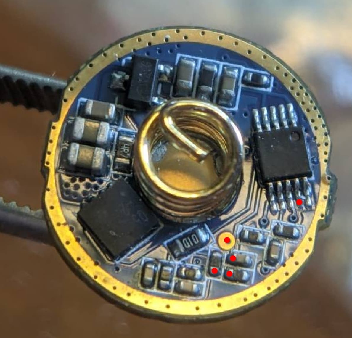
No prog pad:
3V 8A 20mm buck
6V 8A 22mm boost, it has a tiny pad almost underneath the corner of the MCU but I don’t think it’s connected to the programming pin
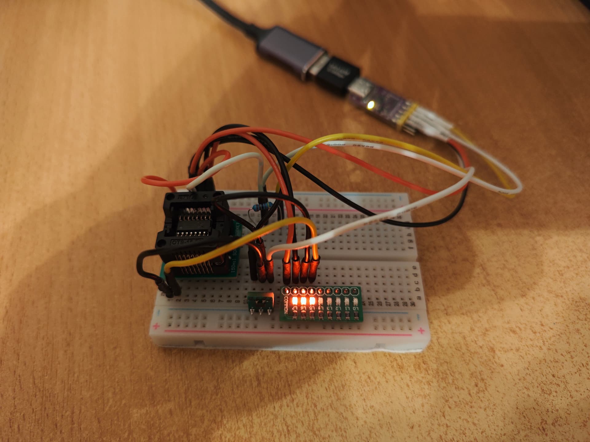
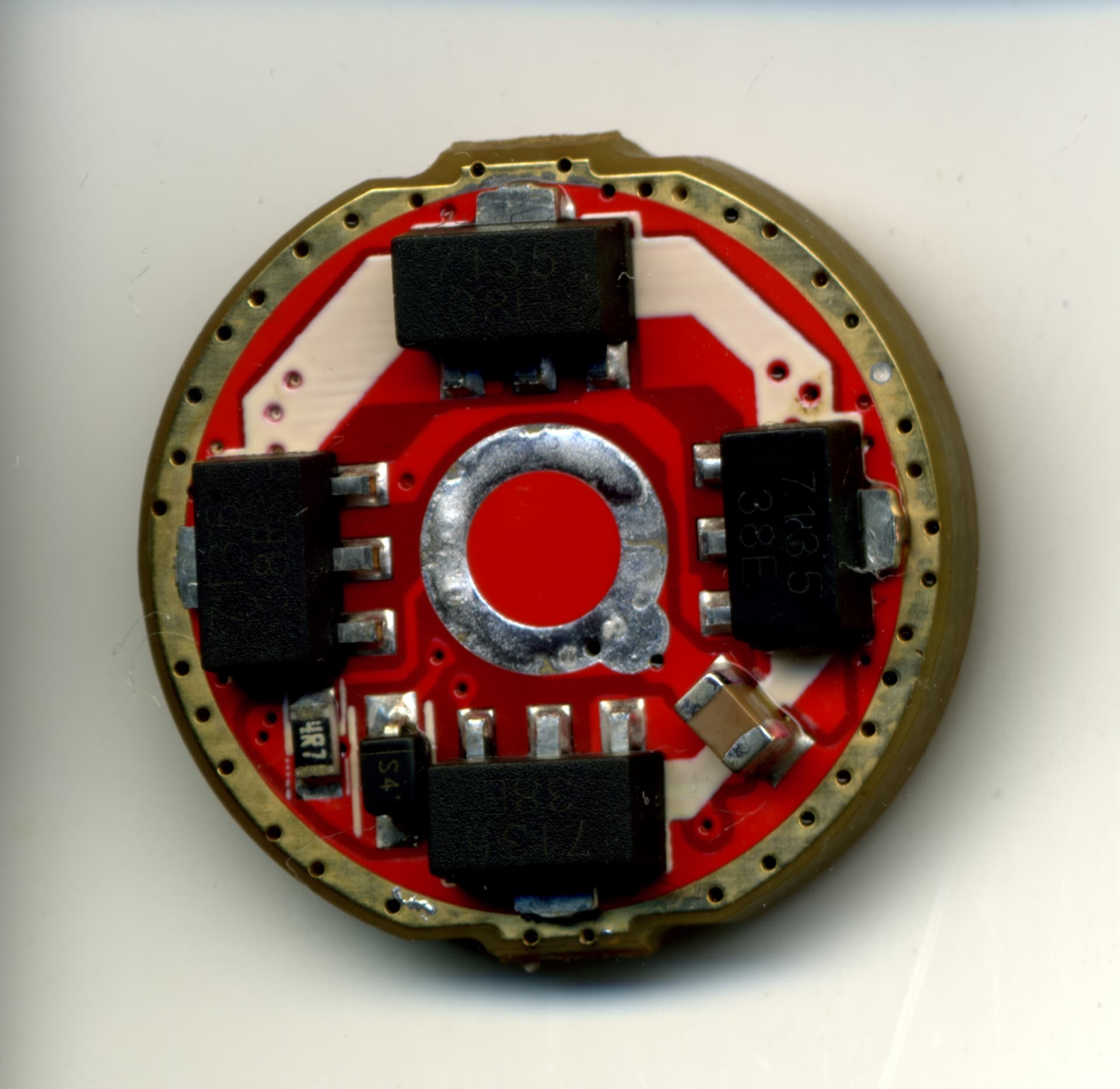
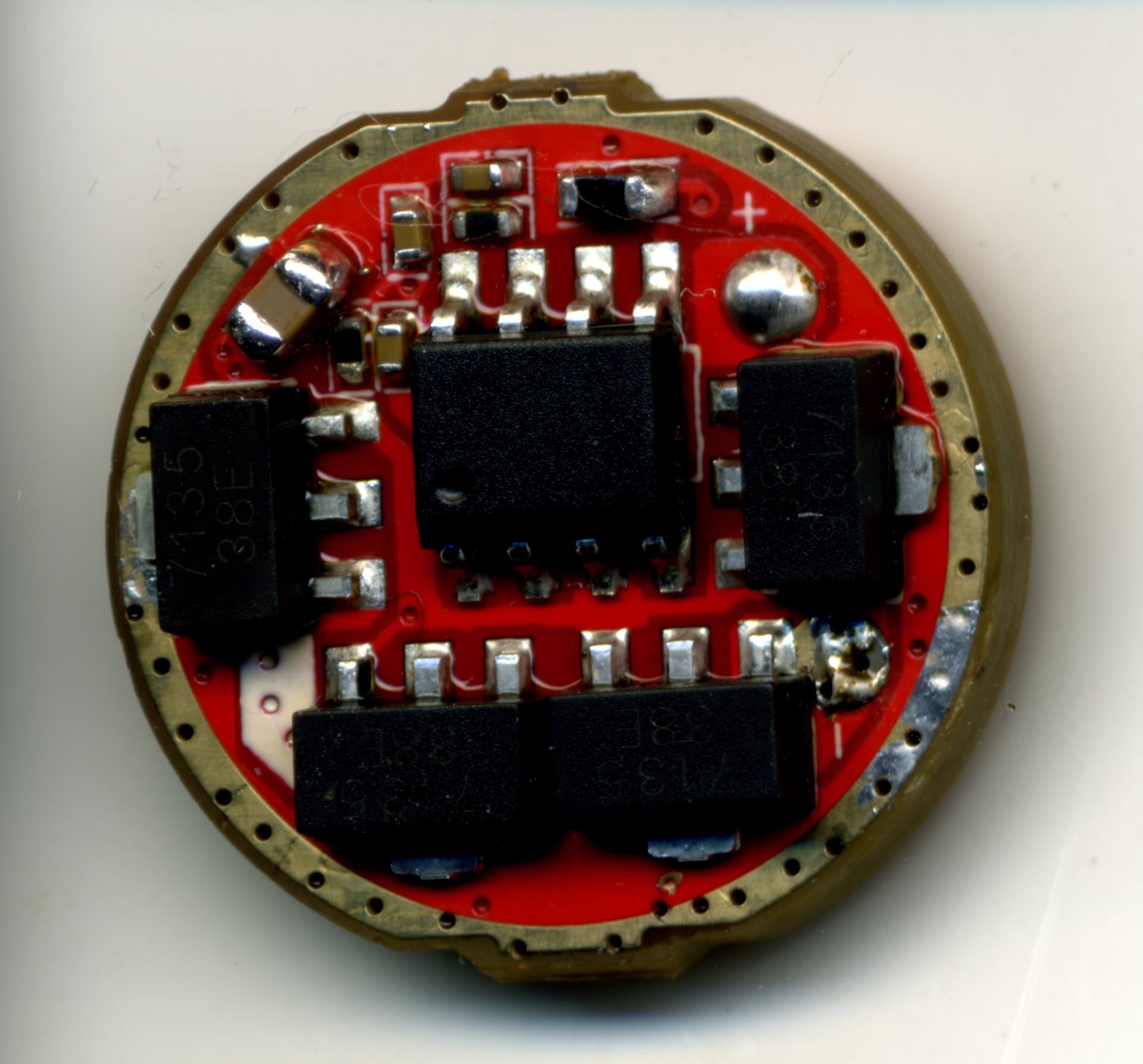
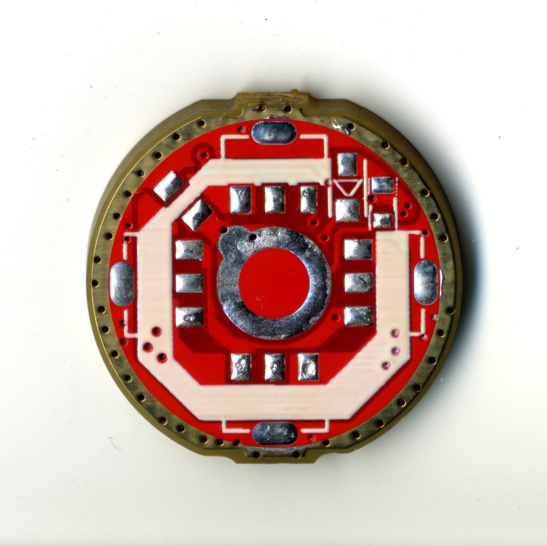
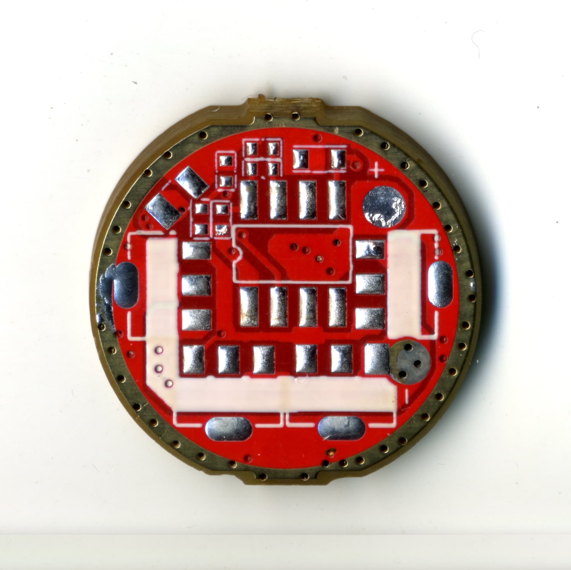
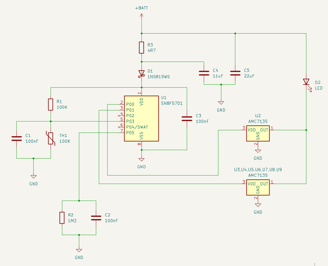
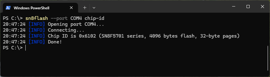
Got myself a couple of simple 7135 drivers from Convoy: discovered that they use Sonix chip as well (SN8F5701), and SWAT pin is not connected to anything. They can be flashed by soldering a wire to pin 6 of the MCU. I’ve decided to use these drivers as training wheels – they are easy to reverse-engineer, and similar to hardware that Bistro firmware currently supports.
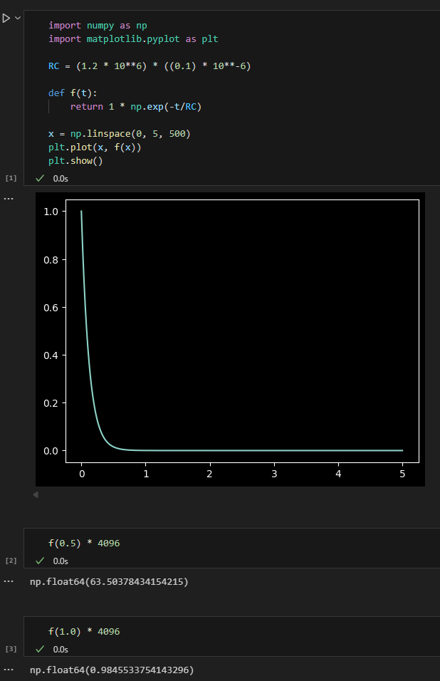
Started working on firmware, faced the first obstacle: Bistro UI uses short clicks (< 1.0s) and medium clicks (1.0s to 4.0s). But the RC constant of R2*C2 is not enough to track delays this long, the voltage falls below ADC resolution in one second:
This is not the end of the word, as it can be fixed by soldering an additional capacitor between MCU pins 7 and 8. But now I wonder whether the 5A dual-fuel driver has the same flaw – if that’s the case, it can’t be fixed this easily, as all components there are tiny.
I just released the flashing dongle files, the release folder contains Gerber, BOM and position files that can be ordered from jlcpcb directly. Other fabs will be able to manufacture these PCBs too if you want to assemble manually, but the assembly files are specific for JLC.
If anyone ends up ordering these boards, please report back that they work so I can mark it as “tested” in the github repository!