Hello! Back to DIY stuff. A couple long heatsinks and some emitters lying around, which I'm planning to set on top of my AC powered main bathroom furniture for some ceilingbounce illumination. Planning to drive 4S emitters (1x XHP50A + 2x LH351Ds) on each heatsink and power them with 2x waterproof Qihang QH-10LO2-3×3W drivers. Yep, they are specified for 2-3S emitters but I know they'll handle the above 4S, less than 12V of combined Vf anyway. I was going to ask about the recommended output capacitance, considering that other Qihang drivers I've used in the past had minimal capacitance in the primary (to maximize power factor). However, just found a couple links which seem to indicate that the above drivers indeed feature 10µF at the primary:

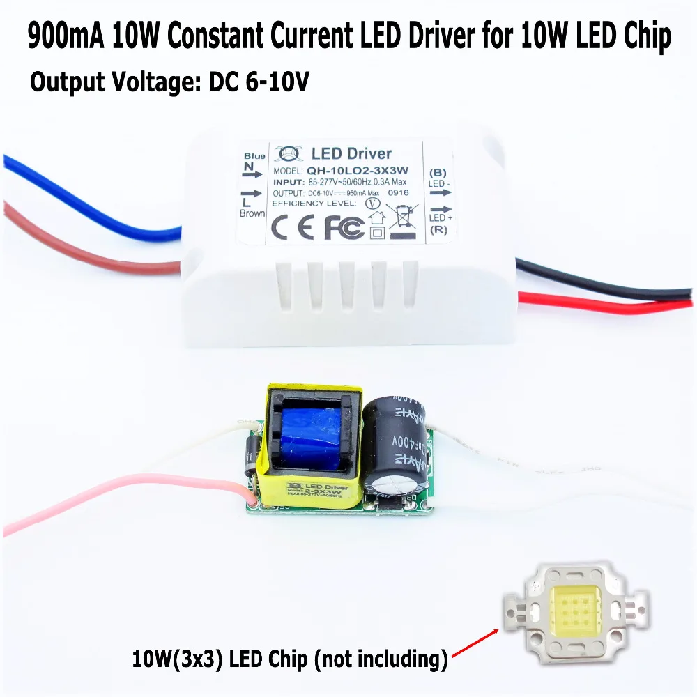
This is how the drivers I plan on using look. Related link.
Since I wasn't planning on dissemboweling them, I looked for a way to find pictures of its innards. And well:

I bet this is the same driver, only in raw circuit board and standard plastic case variants. Related link.
This is where I see the 10µF cap at the primary. I planned on increasing the output capacitance, which indeed I should do since there's nothing. But nowhere near what I was going to ask about: 2200µF for each out of a couple vintage Anodia 16V caps LoL.
Considering the aforementoned presence of a 10µF cap at the primary… mmm don't really know for sure. Looking at other drivers (a 20W 600mA Dark Energy unit with 25µF input caps only had ≈100µF if not mistaken; a 20W 650mA Qihang unit with a very small polyester input cap lying around at home, 440µF at the output) tells me that 220+µF should be 0K already. A bit above that figure shouldn't hurt, doesn't it? ![]()
Nearly concocted my own answer, yet I still wanted to share so here it is.