ANDURIL USER MANUAL & LIST OF LIGHTS

When I was calibrating my SC31pro, just holding it in my hand had the temp increase (on blinkout) 1° and then 2° in just a minute or two, so you need to do it fast. And keep the light overnight right next to a thermometer so you can see at a glance the temperature and let both equilibrate.

Next day or however long, go immediately to the temp blinkout and verify what it tells you vs the thermometer temp. If too different, then again, immediately do the calibration, and another temp blinkout to verify that it stuck.

21°C, holding it in a 37°C hand, it’ll warm up a few degrees very quickly.

Ahh, ok. I forgot the details but I think the first reading was perhaps a bug.

As LB said, it's very sensitive. All these calibration issues go away with the Atmel 1-series (1616, 3216) since they are factory calibrated.

Hi! Could you tell me, https://bazaar.launchpad.net/~toykeeper/flashlight-firmware/fsm/view/head:/ToyKeeper/spaghetti-monster/anduril/cfg-ff-rot66g2.h applied for any ROT66 II on factory (with any Leds?)
And please, could you tell me config for EDC18 and Astrolux HL01

Thank you!

Damn God.
In ~toykeeper/flashlight-firmware/trunk : contents of PRODUCTS at revision 249 HL01 should be Anduril / cfg-mateminco-mt07.h
BUT in ~toykeeper/flashlight-firmware/trunk : files for revision 247 no such cfg file

So, is there any way to discover settings for Astrolux HL01?

Sorry, don't own a HL01, if I did, you'd have the info you want. Dunno if anyone did a tear down to provide details on the driver. Once we know the driver, could probably get the proper Anduril build for it. Unfortunately, Astrolux hasn't communicated well back the the community so TK probably isn't aware of the HL01's Anduril setup.

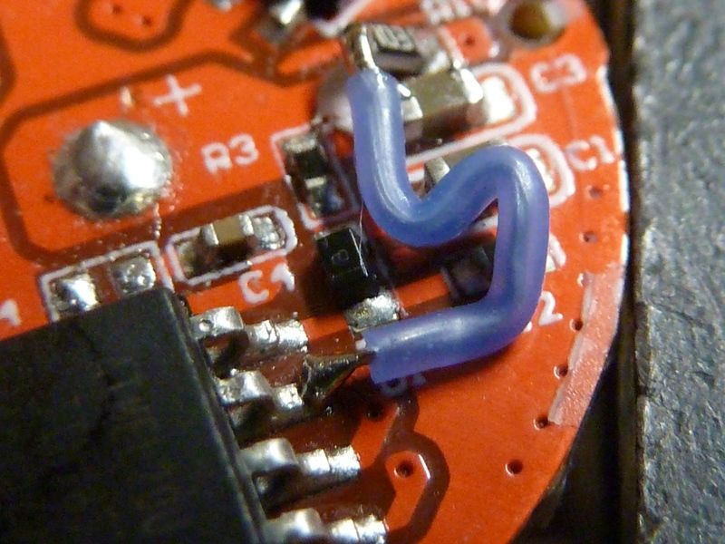
For the EDC18, I'm sure I have, or could make an Anduril cfg file for it. Just checked - back in April 2019 I did a custom config for Anduril 1.1 on the EDC18, adding support for the AUX/switch LED. I rewired the switch LED so Anduril controls it.

Thank you for your answer. Is this modding reviewed anywhere here in detail?

Hhhmmm, good Q. Here's my EDC018 pic album: https://app.photobucket.com/u/TomE2012/a/a12dfc4e-d6a7-4530-8520-0dbfc3591a50

It shows the mod.

you just add this wire to 1 leg of controller?

Sorry, was at work - home now. Reviewed and trying to recall (at my age, that can take a while...). This is what I did:

  • Removed R4 - was connected to pin #7 and does nothing anyway (from TK's experimenting with detecting input from the main LED)
  • Removed R10 - original hard wired resistor for the switch LED
  • solder in a 10K resistor, tomb-stoned -- be sure there's no contact to the "+" pad
  • solder a 30 AWG wire from pin#7 to the 10K

So, the end result, as shown, is I got a switch surface mount LED connected to MCU pin #7, with a 10K resistor in between, as shown:
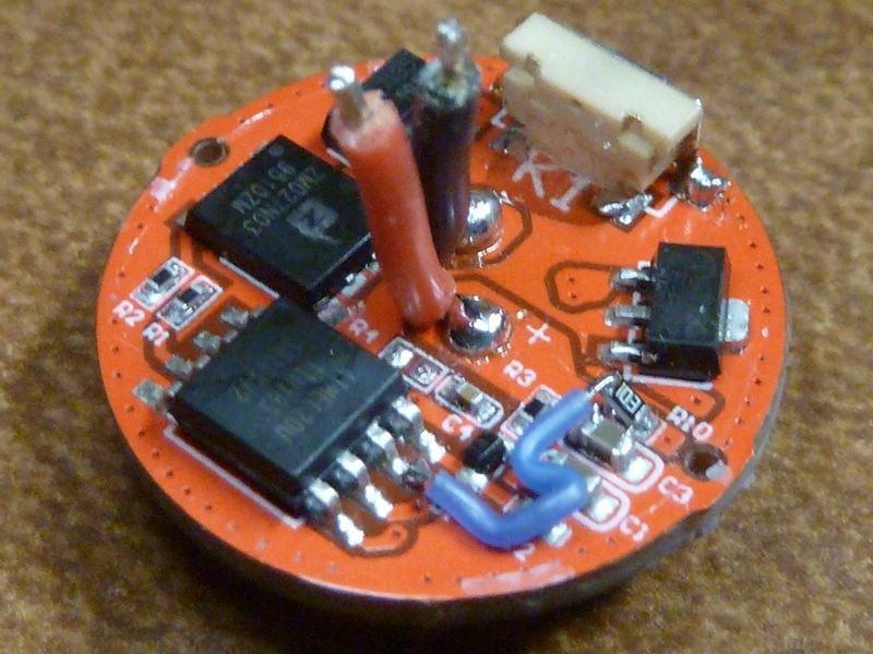
Now Anduril has to be tweaked to support this hardware configuration. So this is the Anduril hwdef file I used, hwdef-EDC18.h:


#ifndef HWDEF_EDC18_H
#define HWDEF_EDC18_H

/* BLF/TLF EDC18 driver layout
*
* The Lumintop EDC18 is basically the same driver as used in the FW3A, but has the e-switch mounted on the driver PCB.
* For my custom EDC18, I removed the resistor off of PIN #7 for the "optic nerve" and wired a jumper to the switch LED
* resistor - using 10K for now, and had to tombstone the resistor to break the connection to Batt+. This will allow
* Anduril to control the switch LED from pin #7
* ----
* Reset -|1 8|- VCC
* eswitch -|2 7|- switch LED (0402 under the switch with 10K 0603 resistor, removed (20K 0402)
* FET -|3 6|- 7x7135
* GND -|4 5|- 1x7135
* ----
*/

#define PWM_CHANNELS 3

// ... the modded EDC18 has aux switch LED on pin 7
#ifndef AUXLED_PIN
#define AUXLED_PIN PB2 // pin 7
#endif

#ifndef SWITCH_PIN
#define SWITCH_PIN PB3 // pin 2
#define SWITCH_PCINT PCINT3 // pin 2 pin change interrupt
#endif

#ifndef PWM1_PIN
#define PWM1_PIN PB0 // pin 5, 1x7135 PWM
#define PWM1_LVL OCR0A // OCR0A is the output compare register for PB0
#endif
#ifndef PWM2_PIN
#define PWM2_PIN PB1 // pin 6, 7x7135 PWM
#define PWM2_LVL OCR0B // OCR0B is the output compare register for PB1
#endif
#ifndef PWM3_PIN
#define PWM3_PIN PB4 // pin 3, FET PWM
#define PWM3_LVL OCR1B // OCR1B is the output compare register for PB4
#endif

#define ADC_PRSCL 0x06 // clk/64

// average drop across diode on this hardware
#ifndef VOLTAGE_FUDGE_FACTOR
#define VOLTAGE_FUDGE_FACTOR 7 // add 0.25V
#endif

//#define TEMP_DIDR ADC4D
#define TEMP_CHANNEL 0b00001111

#define FAST 0xA3 // fast PWM both channels
#define PHASE 0xA1 // phase-correct PWM both channels

#define LAYOUT_DEFINED

#endif


This is the Anduril cfg file I used:


// EDC18 config options for Anduril
#include "hwdef-EDC18.h"

// the button lights up
#define USE_INDICATOR_LED

// the button is visible while main LEDs are on (2020-02-09 TE: enable this!!)
#define USE_INDICATOR_LED_WHILE_RAMPING

// enable blinking indicator LED while off
#define TICK_DURING_STANDBY
#define STANDBY_TICK_SPEED 3 // every 0.128 s
#define USE_FANCIER_BLINKING_INDICATOR
// off mode: low (1)
// lockout: blinking (3)
#define INDICATOR_LED_DEFAULT_MODE ((3<<2) + 1)


// ../../bin/level_calc.py 1 65 7135 1 0.8 150
// ... mixed with this:
// ../../../bin/level_calc.py 3 150 7135 1 0.33 150 7135 1 1 850 FET 1 10 1500
#define RAMP_LENGTH 150
#define PWM1_LEVELS 1,1,2,2,3,3,4,4,5,6,7,8,9,10,12,13,14,15,17,19,20,22,24,26,29,31,34,36,39,42,45,48,51,55,59,62,66,70,75,79,84,89,93,99,104,110,115,121,127,134,140,147,154,161,168,176,184,192,200,209,217,226,236,245,255,255,255,255,255,255,255,255,255,255,255,255,255,255,255,255,255,255,255,255,255,255,255,255,255,255,255,255,255,255,255,255,255,255,255,255,255,255,255,255,255,255,255,255,255,255,255,255,255,255,255,255,255,255,255,255,255,255,255,255,255,255,255,255,255,255,255,255,255,255,255,255,255,255,255,255,255,255,255,255,255,255,255,255,255,0
#define PWM2_LEVELS 0,0,0,0,0,0,0,0,0,0,0,0,0,0,0,0,0,0,0,0,0,0,0,0,0,0,0,0,0,0,0,0,0,0,0,0,0,0,0,0,0,0,0,0,0,0,0,0,0,0,0,0,0,0,0,0,0,0,0,0,0,0,0,0,0,2,4,6,8,10,13,15,17,19,22,24,26,29,31,34,37,39,42,45,48,51,54,57,60,64,67,70,74,77,81,85,88,92,96,100,104,108,112,116,121,125,130,134,139,143,148,153,158,163,168,173,179,184,189,195,201,206,212,218,224,230,236,243,249,255,255,255,255,255,255,255,255,255,255,255,255,255,255,255,255,255,255,255,255,0
#define PWM3_LEVELS 0,0,0,0,0,0,0,0,0,0,0,0,0,0,0,0,0,0,0,0,0,0,0,0,0,0,0,0,0,0,0,0,0,0,0,0,0,0,0,0,0,0,0,0,0,0,0,0,0,0,0,0,0,0,0,0,0,0,0,0,0,0,0,0,0,0,0,0,0,0,0,0,0,0,0,0,0,0,0,0,0,0,0,0,0,0,0,0,0,0,0,0,0,0,0,0,0,0,0,0,0,0,0,0,0,0,0,0,0,0,0,0,0,0,0,0,0,0,0,0,0,0,0,0,0,0,0,0,0,0,8,19,31,43,55,67,79,91,104,117,130,143,157,170,184,198,212,226,240,255
#define MAX_1x7135 65
#define MAX_Nx7135 130
#define HALFSPEED_LEVEL 14
#define QUARTERSPEED_LEVEL 5

//-----------------------------------------------------------------------------
// Thermal Settings
//-----------------------------------------------------------------------------
// optional, makes initial turbo step-down faster so first peak isn't as hot
// the D4 runs very very hot, so be extra careful
//#define THERM_HARD_TURBO_DROP

// stop panicking at about 3A or ~1100 lm, this light is a hotrod
#define THERM_FASTER_LEVEL MAX_Nx7135

// respond to thermal changes faster
#define THERMAL_WARNING_SECONDS 3
#define THERMAL_UPDATE_SPEED 1
#define THERM_PREDICTION_STRENGTH 4
//-----------------------------------------------------------------------------

// Set it much higher than the default of 70C
#define MAX_THERM_CEIL 80


I'll probably convert this over to work with Anduril 2. Also I got two more EDC18's to make this mod to.
Well done! As i understand, we could only change power on led (low, high), turn it off and makes blinking? No way to show battery stats?
Is it difficult to remove driver?

Thank you, man!

  1. Yes, limited to 2 levels
  2. In Anduril and Anduril 2, battery stats is blinked out on the switch LED 3C in the lower output setting
  3. I've broken driver glue seals many many times - see below

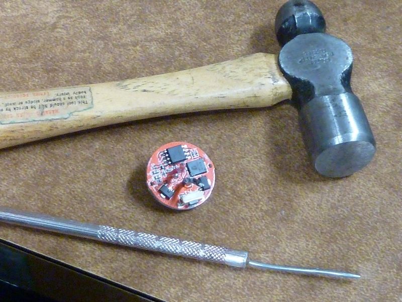
I always start with the solder pick tool going through one of the LED wire holes. It usually fits in there fine with the wire, tight fit though. Trick is to feel around with the solder pick to be sure you are not on a component, closer to an outside edge the better. I'll try simply applying pressure first without the hammer. If that doesn't work, then the hammer comes out. Start with light taps initially - be as careful as you can, but sometimes heavier blows are needed

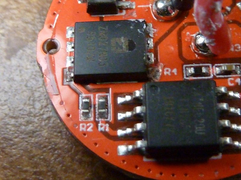
With the driver out, you can see the traces of glue around the edge. Also in this case, I did make some minor damage to the driver at around the R4 label below at the lower pin of the FET. Fortunately, the 4 pins on that side of the FET are redundant, so no damage. Of course this is fairly low risk for me because I could replace components, repair a driver like this one easily.

Do you mean tripple click? And switch led would blink? As i know by 3C we come into Voltage-Temperature-…. circle.

All this definitions in youur config file, where i can find full list of preprocessor constants used in different configs? Some of them i even d’t find in direct code
https://bazaar.launchpad.net/~toykeeper/flashlight-firmware/trunk/view/head:/ToyKeeper/spaghetti-monster/anduril/anduril.c

Yes, 3C (triple click). Yes - switch LED blinks out the voltage reading, same as the main LED(s).

For the compiler switches (preprocessor constants), I though I saw a full list somewhere that TK put together - can't find it now.

This file has some more defined: https://bazaar.launchpad.net/~toykeeper/flashlight-firmware/trunk/view/head:/ToyKeeper/spaghetti-monster/spaghetti-monster.txt

Not sure if this is something TK planned to do or not, or maybe it does exist somewhere, not sure.

Some preprocessor options are for FSM (the framework used by Anduril), but most are options for Anduril and these are not documented in a separate file (yet), only at the place of definition.

Do yo know, In Which flashlight this chips used?

The one I have in my hand right now - a modded Eagle Eye X1R, 18350 right angle/headlamp. gchart has a couple more, not sure if anyone else.

Only in modders hands for now, til manufacturers can get on-board, thread here: https://budgetlightforum.com/t/-/55911

I'll have a few more soon - parts/boards are on their way.

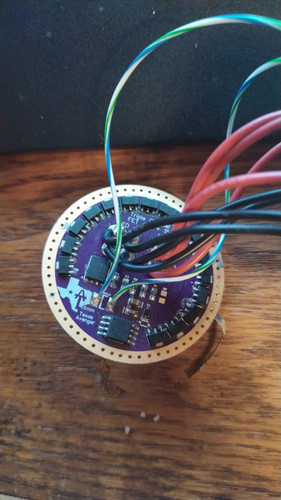
I'm unsure about where to post this, but I guess I'll ask it here. I'm rebuilding an old Sky Ray King I've had kicking around for years, and I would like to use Anduril. The driver I'm using is one of the Texas Avengers boards (46mm) so it's a 3 channel driver. My problem is that I can't seem to get it to switch over the FET direct drive mode (turbo). And which one of the hex files from here would be the most compatible with this driver?

http://toykeeper.net/torches/fsm/anduril2/

This is the driver in question:

Any help would be greatly appreciated.

kelsey - Not sure how much you know. The TA driver is 3 channels, so you need a 3 channel hwdef file, and the pin # assignments of each channel are important. Not sure if any stock Anduril2 hwdef files support that driver, maybe, not sure.

Are you building a Anduril2 HEX file or do you need one, or did you use one? Which one?

I’ve compiled a few drivers to HEX before but I don’t really know what I’m doing. A pre-compiled HEX file would be great, but I’m not familiar with any of the lights and their drivers in that database so I’ve just tried random files. I imagine that code compiled for a triple channel driver would work? Or how do I make it compile so it will work on my end?

I might add that I’ve been trying Narsil as well. Would that be better?

Not all 3 triple channel drivers will work because some use different I/O pins than others. There's 5 basic I/O pins

Two Channels (maybe originated with the Q8):

  • Pin #2 - typically the e-switch
  • Pin #3 - typically the AUX/switch LED
  • Pin #5 - 7135
  • Pin #6 - FET
  • Pin #7 - not used, or if it's a 2S battery driver, then there's a voltage divider circuit on this pin used to read the battery voltage level

For 3 channels, it's tricky because there wasn't a standard established. I'm not sure offhand how TA used the I/O pins. Might need a custom hwdef file, not sure. I'm not home so can't check right now.

At home I could probably do the research and build you an Anduril2 HEX file for that driver, or if someone else can. Best to post on the Anduril2 thread.