Hi everyone!
So this is my first real post here and since my flashlight buying and modding craze is primarily the fault of this fantastic forum I thought I’d stop lurking and sucking inspiration from this place and hopefully return the favour ![]()
So this mod of my Apex 5T6 NW is my most involved to date, before this I did a few driver/emitter swaps on various hosts but this one needed a bit more planning. Not to mention it took a bit more conviction for me to tear apart and potentially destroy a rather fantastic flashlight.
Aims where:
-Boost output per emitter from around 1.7A (the Apex version of this light is claimed to run 8.5A total shared between the 5 emitters) to at least 3A each (15A total).
-Remove annoying PWM for medium and low modes (supposed to be ~120hz). This alone makes this mod worthwhile.
-Beef up heatsinking beneath the emitter MCPCB by filling in the driver cavity and improving heat transfer away from the LEDs.
So it’s nothing too spectacular and I’m certainly not the first to do this kind of mod on here but I’m still rather pleased with how it turned out and maybe it helps someone like me along who wants to turn this great light into a more spectacular and more usable one ![]()
The Driver:
For the driver upgrade I knew I was going to go for the 8x7135 3A drivers from Kaidomain, specifically the 50ma low mode versions. I had used these before in other builds and since I’m not yet able to reprogram Atmel based chips these seemed to offer the best mode options off the shelf. I only really want 3 modes with sensible low and mediums but with these drivers you can just as easily have access to strobe modes in a semi hidden way. Perfect.
The only question was how many of these could I fit inside that driver cavity and hit both my output target as well as maximize the amount of extra heatsink mass I could fit into the head. I really didn’t want to leave any empty space inside that head if at all possible.
I also had to figure out how to wire up the drivers in a master/slave configuration but thanks again to this forum that wasn’t a problem for very long ![]()
I find it useful in planning to be able to visualize things in 3d so I built a rough model of the Apex head in Maya and tried to get a handle on what was possible. It also let me work out a bunch of stuff before even having to tear apart the flashlight.
That looked something like this when I was done with it.
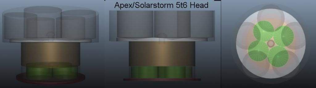
(The green pucks are KD7135 drivers to scale with the height given by adding an extra 7135 on top of each of 4 chips. so the total height of this driver assembly is 7135+pcb+7135+7135 which I worked out to between 6.8 and 7mm)
From this I saw that the most compact approach for the driver would be to squeeze 4 pcbs side by side wired in parallel for a total of 12A and an extra 7135 stacked on as many of the up facing chips as I needed to reach my goal of at least 15A…or better yet 16A…hehe can never have too much power ![]()
I could then also run any thicker connecting wires between the top facing stacked chips and not exceed this total height of 7mm.
The alternative of using either 3 or 5 drivers as a base would have meant a total driver height of more than this ideal 7mm. Using 3 pcbs would have been cheaper but would have meant triple stacking some 7135s and as I said I didn’t want to sacrifice any vertical space inside.
Using 5 drivers was really only a backup plan in case I totally sucked at chip stacking ![]()
with a 16A Goal and 4 driver pcbs
16/4 = 4A each — 3A from stock driver so needs 1A additional current for each driver
1A/0.380 = 2.6 additional 7135s per driver // 10.4 ~11 total extra
1A/0.350 = 2.85 additional 7135s per driver // 11.4 ~12 total extra
I only had 0.350A 7135 chips anyway so that was an easy choice. In total I ended up soldering 18 chips, 12 onto 3 8xKD drivers and another 6 in 3 stacks of two onto a 4x KD board. (fun day :P)
This whole mess worked out as 28x0.380A and 18x0.350A for a total of 16.94A maximum current. Strange… wonder where that extra amp came from?…hah ![]()
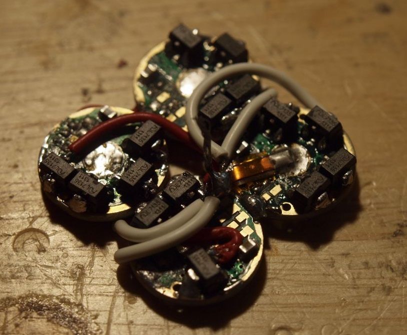
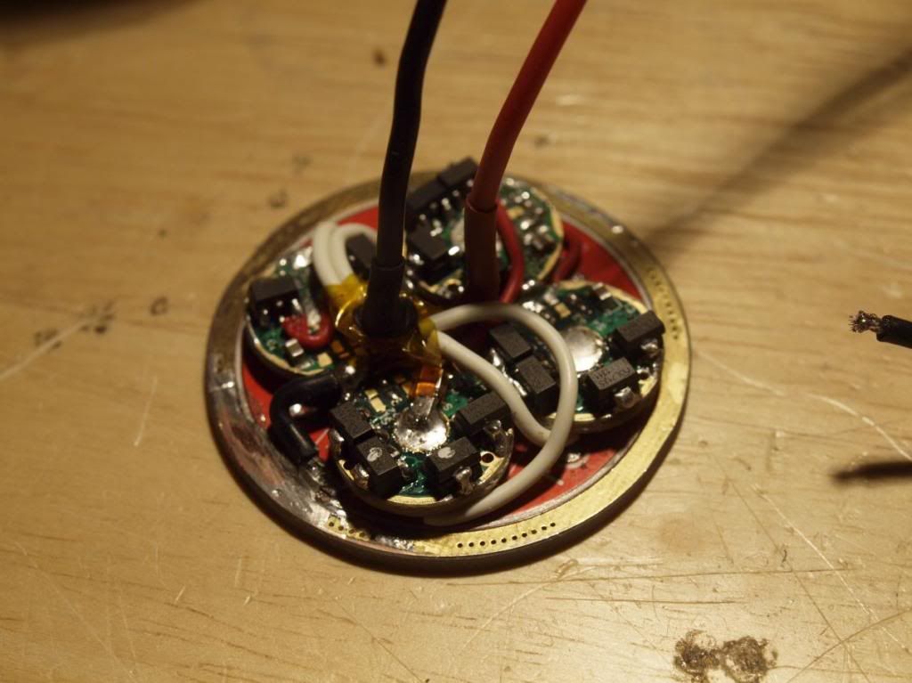
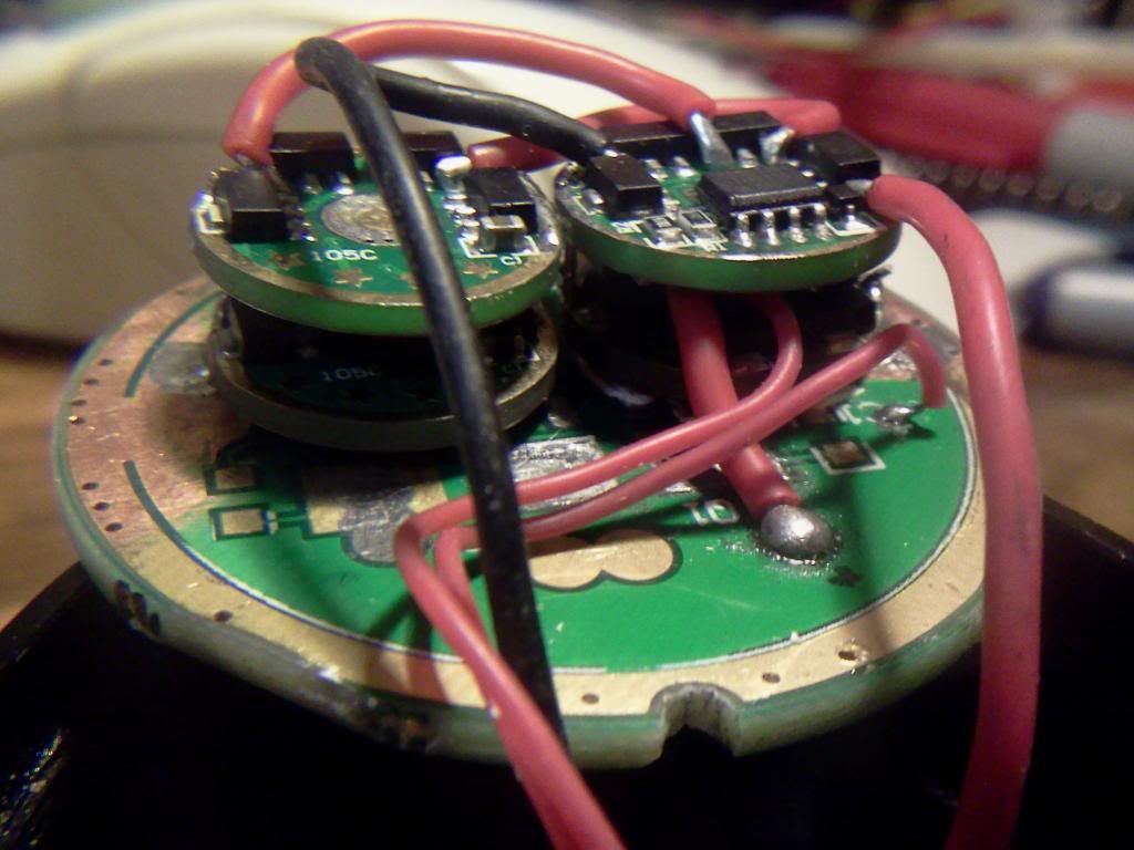
Here is a view of the top of the assembled driver array. The white wires are LED - and the red wires are connecting 7135 right pins to parallel the slave boards. Most of these are on the bottom but I ran out of space for the last one and the short one fixes a damaged pcb path on the 4x board by connecting that bank directly. The Copper strip connects to the + pad on the master controller (right pcb) and provides power for the array from the middle + vias on the Apex driver board.
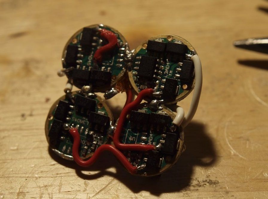
And a look at the bottom. Here you can see the microcontroller on the masterboard and the red wires connecting the slave chips in parallel. The ground rings of all the drivers are soldered together and connected to the - on the Apex contact board.
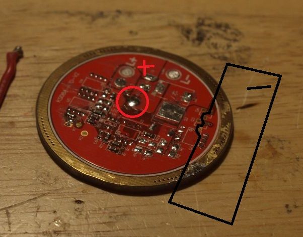
Speaking of which here is the Apex driver board with most of the components removed and showing where I pulled battery + and - from. The + section in the middle of this board is directly connected via a number of vias to the battery contact rings on the other side and I didn’t feel I needed to beef up the connection here at all. For the -/ground I had to find a way of getting a solid point to connect to without increasing the thickness of the board much. The ground ring sits flush on a shelf in the head so if the board gets even a little bit too thick there it becomes very hard to screw the body onto the head and won’t bottom out at the right spot.
To solve this I decided to solder on a thin copper strip that connected to and covered the main outer ring and also connected to a number of the ground pin pads that are in the area marked with the black border. I could then file down the part of the copper strip that was covering the outer ground ring and minimize the thickness I added to the board.
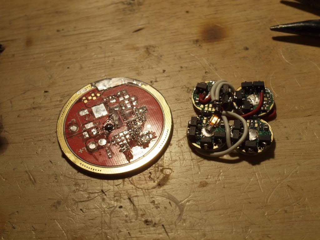
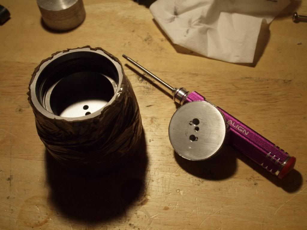
This shows the contact board and driver puck, with the copper strip extension of the ground ring before I filed it down as flat as possible, not too happy with that method but it works ok. Maybe a better way would be to remove the dielectric coating on the whole area and solder to the pad directly.
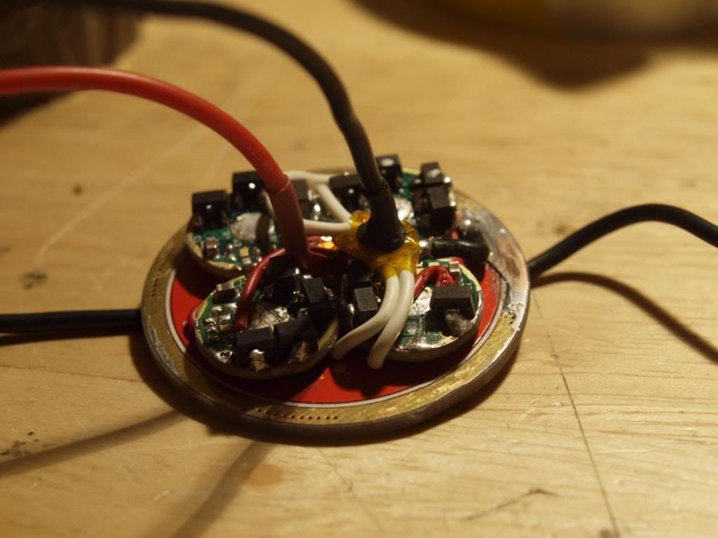
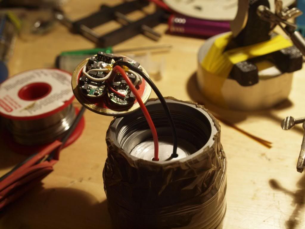
And finally here’s the fully assembled driver ready to be installed. Getting everything lined up and soldered in place was quite fun as there is very little room for error and the copper strip connecting the + to the master board was very fiddly to align. The -/ground rings of the drivers were soldered to the copper strip ground pad using a short piece of 18awg black wire. Also of note here is that the + coming off the Apex board is directly wired to the LEDs + on the led board. Thankfully the + pad on the Apex board is slightly offset from center so that aided in letting me align the + 18awg wire straight up into the hole drilled through the heatsink block…but more in that in a bit.
Suffice to say this was all really cramped and took a fair bit of fiddling and rearranging to align everything. I’m pleased to say I didn’t have to resort to decreasing the calculated size of the heatsink block and most of the 7135 chips are flush up against the alu block when the driver board is fully seated against the groove it’s supposed to sit in. So the body screws on just as it used to.
Heatsink Mass:
Now for that heatsink improvement that constituted such a tight squeeze for the driver.
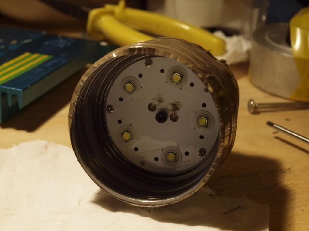
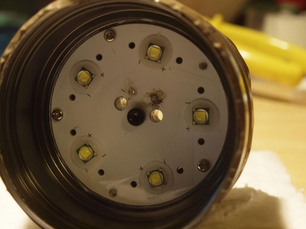
It’s really nothing special, just a large chunk of aluminium bar stock 40mm diameter, lapped to make good contact with the led mcpcb and screwed in to suck as much heat off it as possible. This lack of contact area below the leds is definitely the weakest part of this flashlight design so anything you can do here will be an improvement. Of course a solid chunk of copper would be even better but I didn’t have anything like that on hand.
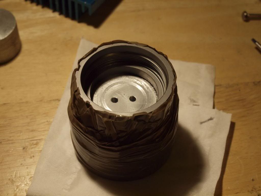
I worked out that with the above driver height of 6.8mm I needed a piece of aluminum of around 15mm height to get a very good fit. Luckily I had one exactly that size in a box of bits and didn’t need to track down someone who could machine it for me. After lapping and cleaning up it was precisely the right size to give me that tight fit on the driver cavity. I forgot to take an exact measurement of the block before final assembly but if you’re keen to try this mod 40x15mm and the driver configuration I gave above should make for a good fit.
To attach the block to the mcpcb I drilled and tapped an M3 hole using the middle hole of the mcpcb as a guide. Then drilled two further holes at I believe 4mm for the two LED wires.
To assemble I used an aluminium foil wrap to get a tight fit in the body and applied some thermal compound to aid heat transfer between it, the pcb and the body of the head. To screw it down I used an M3 hex head bolt and made sure everything was nice and tight.
It works well but here you could make some improvements for sure. As I said a big copper block would be better and machined for an interference fit into the head of the light would be ideal. But how much difference this will actually make to output I have no idea. As it is it definitely helps control the heat from the mcpcb for a little while and as an added bonus balances the light out nicely with a good increase in heft to the head.
For final assembly I glued the driver board into the head using Fujik and applied some thermal compound to the tops of the 7135 chips where they make contact with the aluminium block.
Testing so far has been really fun, on high this thing is crazy, crazy bright and combined with some really nice tint NW emitters it’s an absolute joy to use outside at night. I’m not going to attempt to speculate on total Lumen output or lux and don’t have the equipment to make accurate measurements so I’ll just say it’s a heck of a lot brighter than before and the low and medium modes are considerably more usable due to not having that annoying flicker. I did do some indoor comparison shots but unfortunately the difference is not all that representative in those photos, should have done a test outside. Maybe if I get a second one of these lights at some point I can do a better direct comparison.
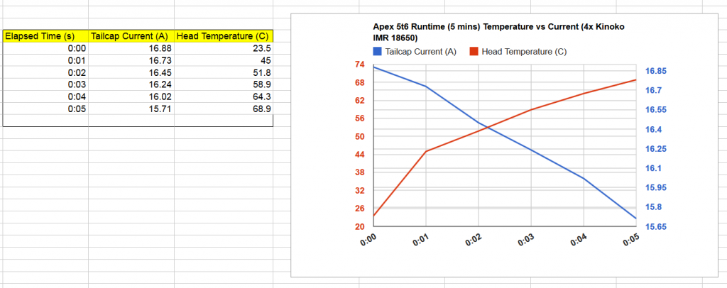
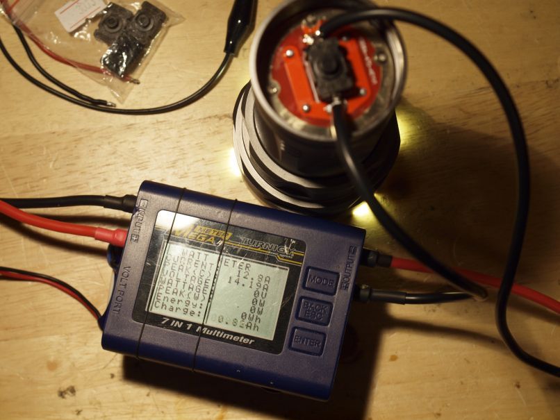
The tailcap readings taken across the switch with a beefy Watt meter that I trust more than my multimeter are as follows.
Test Setup:
Note: This is with a somewhat tired, 1 year old set of Senybor 2400mah 18650s,
High: 14.5-14.9A
Dropping slowly but steadily from there on down, not surprising considering the heavy load. I believe average stable current after a few minutes was around the 12-13Amps. Not bad
Med: 5.3-5.7A
Good light level for this light, close to being as bright as High mode was before the mod and can run indefinitely without cooking itself to death.
Low: 0.225A
Quite low but very useful, I have it set to come on in low without memory so this avoids blinding anyone nearby when you go outside and lets your eyes adjust.
I have some kinoko IMR 18650s coming from Illumination supply which should provide a bit more juice for more testing. Even just one of these cells can power this light to 8.5A so I bet 4 will do great.
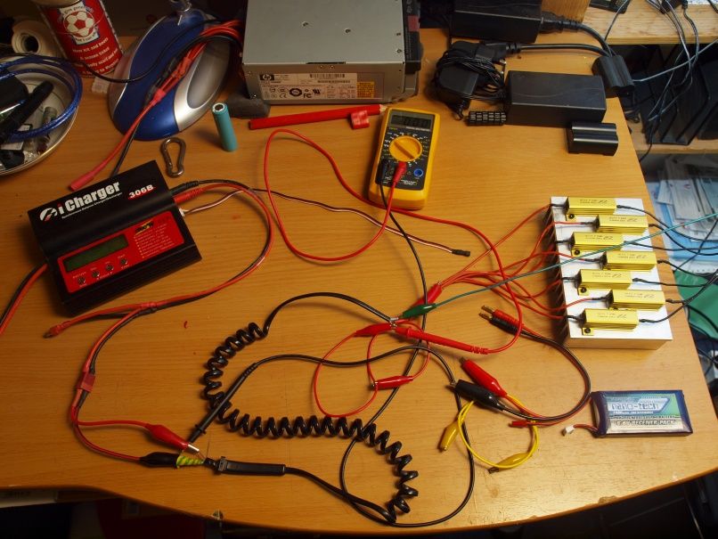
In the meantime out of curiosity I wanted to see if all my 7135 chips were alive and well so I hooked up a beefy rc lipo battery that won’t sag like the 18650s and got a solid steady current around where I was expecting ~16.8A. This test also made me keen to build a version of this light using an external Lipo power pack for extended high power ![]()
So that’s about it, sorry if it was a bit long but hopefully it’s useful to someone attempting a similar mod.
In any case I can wholeheartedly recommend doing something like this on the Apex 5t6. It’s a lovely light and deserves some extra power!
Cheers
Linus
 You are an inspiration to us all (or me, at the very least)!
 Of course, we still need beam shots.