Some capacitors have the metal contacts on the ends slightly larger than the dimensions of the body. If the pencil has a rounded point it may not get all the way into that right angle where the contact meets the body, leaving a gap in the graphite. You might need to press harder or sharpen the pencil.
The right one it was! Put a few streaks over it with a well sharpened pencil and now the light always starts up on high mode now. Thanks!
I must admit, I did check the date on the posting that mentioned the pencil trick. Despite the following posts I had to check that it wasn’t posted on 1st of April ![]()
bump
can this mode work on a nanjg 105c 8x7135 driver?
No, capacitor on a 105C is used for removing potential power spikes to mcu also 105C memorises in power on state, not power off
but, on other hand you can reprogram attiny13a with one of many wonderful firmwares provided by valued blf members.
P.S. Nanjg 105C doesnt have next mode memory!!!
STAR V1.1, solder down pin 4 memory gone
I happen to like soldering pins 2, 3, 4 down
2 = moon mode on
3 = Hi -> Low
4 = memory off (aka start in Hi after turning light off for about 5 seconds)
I moded a flashlight for a friend with this driver : https://www.fasttech.com/products/1186301
as he told me it has last memory. unfortunately I don’t have the equipment to flash a driver.
Then he will have to live with it or you will have to get programmer for atmel ![]()
Easy Peasy
https://www.fasttech.com/products/0/10000022/1002900-atmega-attiny-51-avr-isp-usbasp-usb-programmer
Programmer
http://www.digikey.com/product-search/en?WT.z_header=search_go&lang=en&site=us&keywords=501-1311-ND&x=0&y=0&formaction=on
SOIC interface
Just wire up the correct pins, set jumper to 3.3vdc
 <-pins on ATtiny13A
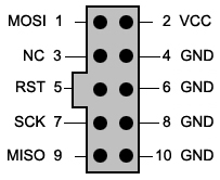 <-pins coming out of avr-isp
tiny13 -> avr-isp
1 -> 5
4 -> 4
5 -> 1
6 -> 9
7 -> 7
8 -> 2
Get AVRDude…and viola…program away
Well you need the AVRISP drivers, here this will help
Once you get the driver loaded, and you get a .hex file to write
copy the batch file and the .hex to c:\usbavr (whatever directory name you want…I used that one because it’s easier to remember)
edit the .bat file and ensure you have the name of the .hex file in the right spot
open a command prompt, go into that directory
then run the usbavr.bat batch file and if you have the pins wired right, viola, it will flash the new .hex to the ATtiny
This is for the Nanjg 105C’s NOT for the other cheapie drivers, the pencil trick is the one for those above drivers…
I might try,thanks for the tips.and again thank you for updating it and making to easier to understand.
What a wonderful and easy mod!
I have a light I really disliked due to it’s next mode memory. Only had 1 capacitor so it was easy to try. Put some penciltrace on it and now it always starts in high. Just as that light should be in my opinion. Takes about half a second for it to turn to high, good enough. Not a problem to switch modes and quick to return to high if I want to.
Thank you!
any ideas about this driver?

Only one cap there… one way to find out ![]()
i tryed to add above the cap various size resistors ,but it didnt work
Yes, I have this type of driver and have done memory reset on it (long time ago - used resistor at the time). So very likely it is still possible.
You can try small grit sandpaper and rub the top clean, then darken the whole thing with pencil. Be generous, this is just to test it. If you get one-mode afterwards (high only), then the reset can work.
Just slowly rub off the pencil trace and try again. At one point you should get the comfortable reset time.
the pencil thing i will do it on the top of the capacitor?
Yes, idea is to make a small connection across the capacitor that will cause it to discharge faster and “forget” in which mode flashlight was when Power OFF accrued.
You first need to clean soldering points (as sugested by Pulsar13) because those contact are often coated with rosin core that is in solder paste and you do this with ordinary graphite pencil because graphite is conductor as you already know…
![]()
It didn't work because that cap is for the MCU power supply filtering, not the memory. It's right by the diode, maybe even soldered onto the same pad.
disregard, comfy already addressed it ![]()
ok guys thanks for the tips.