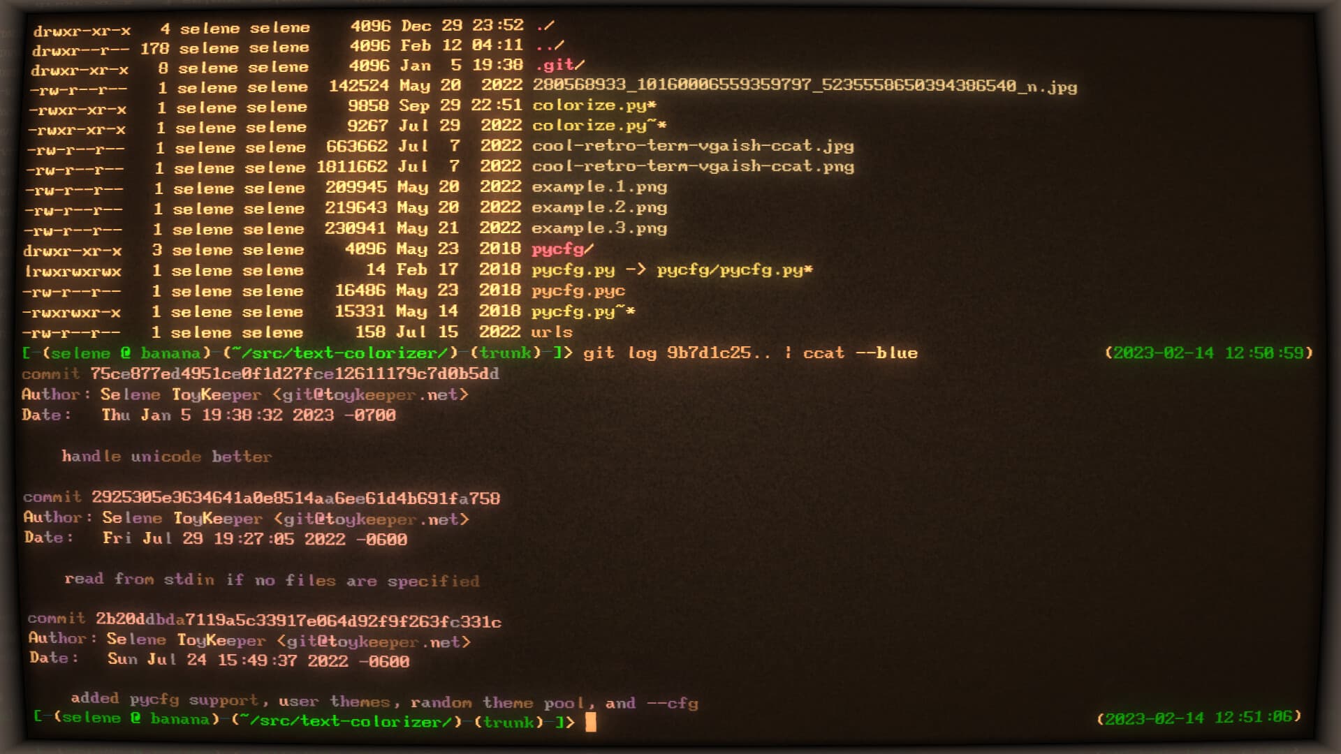
… though usually I go with rxvt-unicode-256color, because it’s waaaay more lightweight and can easily handle running 500 instances at once. The retro term takes a lot more CPU and RAM, so I generally reserve it for times I feel like focusing on just one full-screen window for a while. Usually just for email, but sometimes also code and other tasks.
Probably a good idea anyway for forward compatibility especially if there starts being support for more than 2 channels in the future as that’s going to be a big jump in image size… I think with my builds with everything enabled, I’m getting to 84% on the 1634 now although more like 79% if I set the features I want based on the light’s usage.
Looks like the 1616 just has better specs in general overall as well, plus only 3 pins to flash would be nice as really, what’s near the top of my wishlist is a more reliable way to flash the MCU than pogo pins (some kind of header that a cable can clip to?), as I think I just bricked one today Fortunately not an important light I rely on but still sucks as it’s still an expensive one, and I’m going to assume using HVSP while it’s still on the PCB wouldn’t work even if I had the necessary hardware (maybe I’ll see if someone here can replace it, I guess)
Great choice in editor there. Although I don’t think I’ve ever got close to having 500 terminals open at once, even with tmux
I’d love to have something like this, would avoid incidents like said bricked MCU because I probably flashed 7-8 new builds today testing some changes, I guess when you flash an MCU enough times eventually a cosmic ray gets you and disables SPI… I’d definitely be interested in a way to do testing more safely (perhaps a DIP package MCU so it could be removed and HVSP recovered if that happens?..) Ironically it was the finished version going onto the light after I finished debugging the feature I specifically wrote for that light , but I do overall certainly reflash my lights enough there’s a risk ), PCB design is way outside my skillset but I’d be interested in a group buy or DIY instructions.
That’s how you learn, every expert was once a beginner. One of the reasons I got so interested in this hobby so quickly, so much to learn. Also, welcome
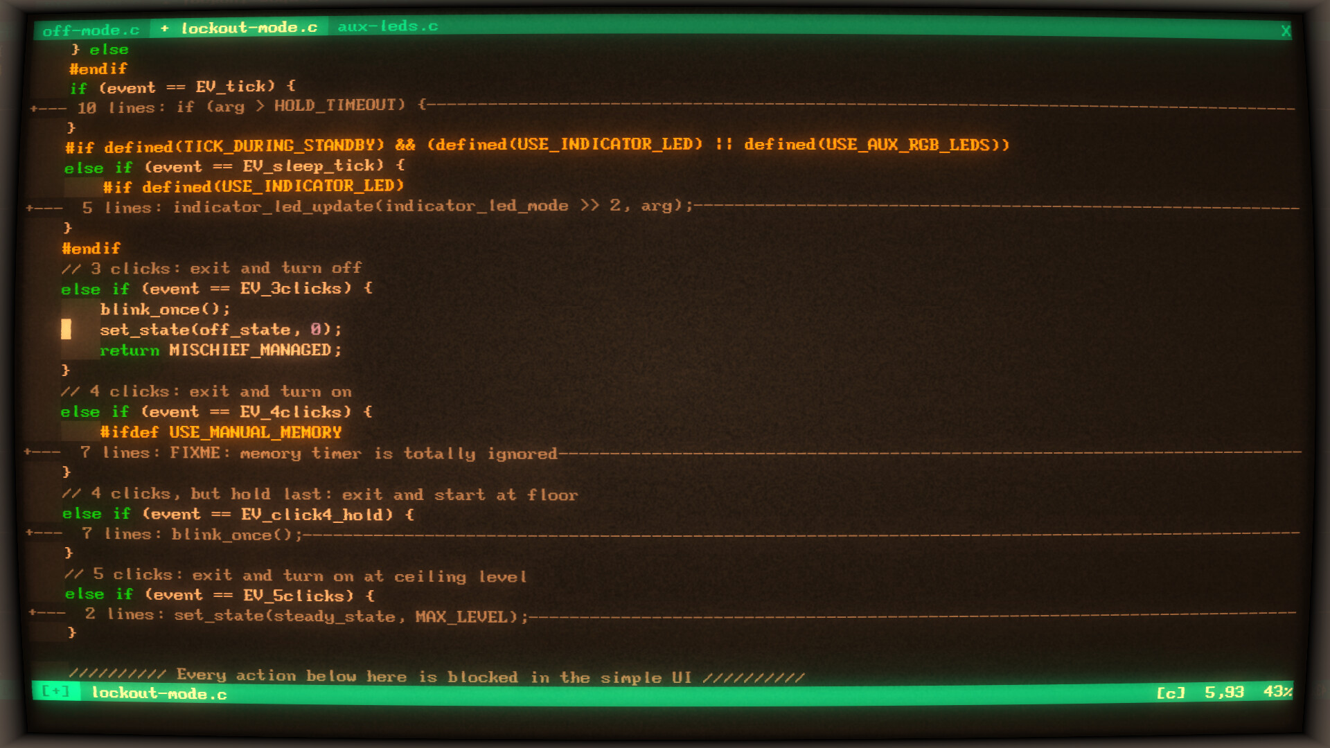
Honestly, the anduril codebase is very easy to understand if you have any development experience, C is an easy language and IMO a breath of fresh air compared to some of the languages I work with for a living (does anyone at all anywhere actually like Ruby or YAML? ), it probably took me a couple of hours of reading it before I started to make simple mods, it provides a really good set of functions to do pretty much anything you might want (I’ve only had to change the underlying FSM code in a few places and mostly small changes), you don’t really strictly need an IDE so much as just any good editor (it does use feature flags a lot so some good autoindenting and syntax highlighting capabilities are probably the most valuable thing).
if you’re familiar with Docker that’s probably the simplest way to build it.
lol Nope… I just have enough C knowlage that it gets me in trouble… I barely know how to git hub. Am a CATscan tech not a dev… But I am reading proffieOS and making boards.
@thefreeman Qu’est-ce qui se passe avec les français qui ont astrix sur leur profil. Sorry my French is a tad rusty. My real second language is sign language.
If you mean like using RGB LEDs for the main LEDs, if they can use 3 pins on the MCU then it would be doable (with some fairly significant code changes) if there are no aux or they use the same RGB value, otherwise it would need more I/O pins.
I just haven’t dived into the documentation for at1616 with that wiring setup. I see that dual channel with rgbs works for the at1634. But like I said I have not dived into the meat.
I just saw a cyan/magenta/warm white rgb set up and found it pleasing. So I want that ability plus dual channel.
If I add the “synthesaber” modes, it’ll definitely bump up the size a couple KiB. And I’m hoping to do that soon, so RGB lights can have a fun completely custom mode group. I’m not sure how best to fit it into the UI though, and it won’t be included on white lights since it makes no sense there.
I haven’t tried HVSP, but some people around here have. I think there are some drivers which can do HVSP without de-soldering, but on most, the extra voltage would probably damage other components.
Before I found rxvt-unicode’s client/daemon feature, I frequently ran into issues where I couldn’t open a new window without closing an old one first, because Xorg uses an 8-bit unsigned integer for the client ID, and I had all 256 client slots filled. But now all my terminals share a single client slot, so I can open as many as I want. Sometimes it has been over 500 total windows open on a single computer, without even counting tabs.
Don’t do this. It’s a bad habit.
I’m sure someone does… but Ruby just feels like a poor imitation of Python with some Perl thrown in. And I almost never have a reason to use YAML, since other formats are usually more appropriate for whatever task I’m doing.
At first, I really really liked Ruby’s “blocks” feature. I liked it enough that I even tried to write a PEP for Python, to propose it as a new language feature. But when I got to the part about showing examples of useful functionality it could add, or do better than the existing mechanisms… I couldn’t come up with even one. I searched and searched and failed to find or invent a single use case where blocks solved a problem better than the solutions Python already had.
So I scrapped the PEP. And since that was basically the only thing I really liked about Ruby, I was left with no reason to ever use it again unless I didn’t have a choice.
Yeah. I should really try to cut back on that. It’s a little ridiculous.
Pushing my EE knowledge here a bit, feeling mildly overwhelmed myself - the TLV333 is an op-amp, right? What’s the function in this context? Right in assuming input 3 is used to provide the actual voltage going out to the LEDs as feedback?
Also, that the regulated portion of each channel actually has a FET but it’s just not a direct drive one (used for PWM? what’s the purpose of the resistor bridging to GND?), or did I get that symbol wrong?
Why I love lights, I’m learning so much across the whole range from low level electrical stuff to microcontrollers. If there are any more complete schematics (in terms of the MCU and things like aux) I’ve love to see them. I have a dead driver lying around but I have no idea where to even start in terms of reverse engineering circuits past the super basic stuff like probing for continuity.
I recently had to learn way more than I ever wanted to know about CT scans and how to read them, and it turned out to be way more fascinating than I expected. I actually really enjoyed it.
Would just be nice if my doctors had done that work instead of me… since it is, like, their job. I had to find what half a dozen doctors missed… which is a little embarrassing if even a noob like me could spot it.
Anyway, super cool tech. It seems like a good field to be in.
K1 :(, was making beacon mode more configurable by being able to adjust brightness and set the length of time each blink is on for (also just updating it with a few of my older changes and to set my config as the factory reset default as I hadn’t got round to reflashing that one yet, I think it might have still been running unmodded anduril at the time (only flashed it once before, from v1 it came with to 2), and with the tactical mode addition seemed like a good time). Feature works perfectly on my other lights, but the light is dead as the MCU lost its device signature . My D4S has survived multiple bad flash attempts and of course it had to happen to my biggest light…
Sadly, in my experience, “educating a doctor on how to do their job” is all too common an occurrence…
Very, very strange that it would get bricked though. If you weren’t setting the fuses, it should be recoverable unless something very improbable happened, like getting boot code corrupted in exactly the wrong way.
It’s probably worth trying again, and again, and again… removing and re-applying the pogo adapter, and potentially even plugging/unplugging the USB dongle. I’ve had some adapters which don’t work until re-plugging, and some MCUs which are just really obnoxiously finicky about reflashing. On some lights, I can’t get it to flash unless I use a loupe or reading glasses to look at the flashing pads very closely while aligning the pogo pins. And my ROT66 took about a hundred tries last time I updated it.
You’ve probably tried all that. But still. Nothing to lose by trying a bunch of times… it only has to work once.
Yes, though I would prefer to get some remuneration for it, for example by doing driver design, in any case there are some details about the implementation and component choice that are important so some discussions between us would be quite recommended.
Note that HDR is best used with the DAC, since at the transition the control signal must change instantly, filtered PWM can’t due to the low pass filter rise/fall time, although Loneoceans did use PWM (1634) in his first version of his lumeX driver, I guess he probably mitigated this problem with a blink, now the Lume FF UDR uses the T1616’s DAC.
And also vice versa, because the DAC resolution isn’t very high, switching Vref technically allows 1:1159 dimming ratio but the 2 lowest level pulse a bit, so it’s really only usable with multiple sense resistors to increase the resolution, if moonlight modes are desired.
Unfortunately using the DAC means only one regulated channel, since there is only one DAC output pin (but even then DAC+HDR wouldn’t work without big changes to the tint ramping code I think).
Anyway I should send you one of my modded light so you see how it works in practice, I’ll send a PM later.
I agree that he should switch to the T1616, even if the all his drivers keep using PWM control, the gain of space is really apreciable with the 3 flashing pad, easier routing and smaller package, 3x3mm vs 4x4mm doesn’t seem like much but when designing small drivers it does make a difference. I would never be able to make an AA/14500 boost-buck driver like this one with the T1634 and 6 flashing pads (also using DAC saves space).
The UPDI flashing adapter designed by Gchart is also more convenient to use (and cheaper to produce).
Aucune idée.
As mentionned just above there is only one DAC output, so for 2 regulated channel PWM muwt be used.
No problem for RGB, there’s just one aux in the schematic here but Anduril supports RGB + button LED I think.
1 series don’t exist in DIP packages I think, it’s only QFN and SOIC, but maybe it could be on a separate board with pin headers.
Yes it’s an Op-Amp, there is the control voltage on the non inverting input from the filtered PWM signal, and the sense voltage from the 10mΩ sense resistor (1206 size on the driver) on the Inverting input.
The Op-Amp will try to maintain both its input at the same voltage with the help of the MOSFET which acts as a variable resistor (the higher the gate-source voltage the lower its resistance and vice versa).
If the LED current increases, the sense voltage increases and inverting input voltage too, which becomes higher than the control voltage on the non inverting input, this makes the output voltage of the Op-Amp decreases, increasing the FET resistance, lowering the LED current. And vice versa, it’s a closed feedback loop.
The compensation components I mentionned prevent ringing (increasing too much, decreasing too much…etc)
Yes, though I would prefer to get some remuneration for it, for example by doing driver design, in any case there are some details about the implementation and component choice that are important so some discussions between us would be quite recommended.
Note that HDR is best used with the DAC, since at the transition the control signal must change instantly, filtered PWM can’t due to the low pass filter rise/fall time, although Loneoceans did use PWM (1634) in his first version of his lumeX driver, I guess he probably mitigated this problem with a blink, now the Lume FF UDR uses the T1616’s DAC.
And also vice versa, because the DAC resolution isn’t very high, switching Vref technically allows 1:1159 dimming ratio but the 2 lowest level pulse a bit, so it’s really only usable with multiple sense resistors to increase the resolution, if moonlight modes are desired.
Unfortunately using the DAC means only one regulated channel, since there is only one DAC output pin (but even then DAC+HDR wouldn’t work with big changes to the tint ramping code I think).
Anyway I should send you one of my modded light so you see how it works in practice, I’ll send a PM later.
I agree that he should switch to the T1616, even if the all his drivers keep using PWM control, the gain of space is really apreciable with the 3 flashing pad, easier routing and smaller package, 3x3mm vs 4x4mm doesn’t seem like much but when designing small drivers it does make a difference. I would never be able to make an AA/14500 boost-buck driver like this one with the T1634 and 6 flashing pads.
Aucune idée.
As mentionned just above there is only one DAC output, so for 2 regulated channel PWM muwt be used.
No problem for RGB, there’s just one aux in the schematic here but Anduril supports RGB + button LED I think.
1 series don’t exist in DIP packages I think, it’s only QFN and SOIC, but maybe it could be on a separate board with pin headers.
Yes it’s an Op-Amp, there is the control voltage on the non inverting input from the filtered PWM signal, and the sense voltage from the 10mΩ sense resistor (1206 size on the driver) on the Inverting input.
The Op-Amp will try to maintain both its input at the same voltage with the help of the MOSFET which acts as a variable resistor (the higher the gate-source voltage the lower its resistance and vice versa).
If the LED current increases, the sense voltage increases and inverting input voltage too, which becomes higher than the control voltage on the non inverting input, this makes the output voltage of the Op-Amp decreases, increasing the FET resistance, lowering the LED current. And vice versa, it’s a closed feedback loop.
The compensation components I mentionned prevent ringing (increasing too much, decreasing too much…etc)
Just as good, I guess, also would allow being able to switch between different MCUs for development purposes as a nice bonus.
I assume most of it would be breadboardable as a prototype but I’d definitely need a comprehensive parts list and would be interested in a few as a more integrated product too.
Of course. And that’s none of my business, definitely something to talk to him about directly.
Yeah, 1-to-1159 isn’t enough. Today’s PWM lights get like 1-to-20,000, and I’d like to take it even higher.
… which is where multiple sense resistors come in.
I just have one concern about those. How hard is it to avoid a bump or zig-zag in the ramp at the transition point?
Like, let’s say Hank produces a driver with a 5A limit, a 9A limit, and a 12A limit… and they use the same firmware. Is it likely that firmware calibrated for one model would have a big bump in the ramp on another model? Would Hank need to make sure the ratios are consistent between the sense resistors on each driver? (like, instead of 0.5A + 5A, 0.5A + 9A, and 0.5A + 12A, he would need to do 0.5A + 5A, 0.9A + 9A, and 1.2A + 12A)
… and more generally, if there are minor variations in resistance between individual parts, would those produce a (slightly) bumpy ramp? Like, let’s say the ramp is calibrated for two sense resistors… 33 Ohms and 330 Ohms. But in production, some are like 32.5 + 337, and others are like 33.7 + 325. Would this mean the transition point would be smooth on some lights and a bit bumpy on others?
This is new to me, so I’m not sure if I’m making the right inferences.
Maybe a calibration factor to compensate similar to how voltage/temperature calibration is done? Values you could adjust for it either resistor is too high or too low vs nominal and feed those into the adjustment? Obviously, can’t measure them all but just as a “If the ramp seems off, here’s what to adjust and how it should affect it”.
I don’t even know if there is an issue yet, or if I’m just hypothesizing about nonexistent things. If it turns out to be an issue, I’ll find a solution. If it ends up being a thing which varies per item and needs user calibration, like the jump start level, I’ll add a calibration. But it might “just work”.
@ToyKeeper Remmeber doctors are more general practitioners. THey are rarely specialist in the field you need them to be in. unless thats exactly what they specilurize in. aalso radiologists miss things they are human… which is why Its important to train AI to catch things for a 2 second pair of eyes. as it were.
Also that sounds like fun. A lightsaber flashlight. And plenty of room for electronics. I wonder if I can get like a scratch and dent from saberforge. or snag a second hand one. I am talking like a proper flash light not a cree saber.