BLF LT1 First Thoughts, Measurements, PWM – Shine On You Crazy Diamond!

This is way more sophisticated that I expected.

I managed to get one of the Amazon deals that Sofirn has going and I got the light last Monday.
I checked the batteries and one was at 3.71v and the rest at 3.93v.
No biggie. Into the Vapecell S4+ for a capacity test. Gotta love 2a charging BTY.
All off them batted above 3000.

The LT1 in its natural environment - The Test Bench

Into the light they went. Now it’s time to play. After setting things up like I wanted, it was time for a run test. I always like to run any new light at max brightness to see if anything unexpected happens.

The LT1 is so well behaved, as I expected, and found no anomalies – Except one.
The darn thing will not stop shining!

After the batteries get to the 2.9v or so, the light steps down to the lowest setting.
And it stays there – I guess forever.
I kept bumping back up to full brightness every time I walked by.
It stepped down and kept shining.

After hours and hours (and hours) of this, I figured the photons were never going to stop dancing– so I turned it off.
Checked the voltage, still 2.9v.

Charging
Plugging in the included USB cable to a high quality USB power supply, it started charging.
The most current I saw was about 1.59a. And it was mostly around 1.48a.
I have seen over 2a from this power source before, and I kind of was expecting more from the LT1.

Later – Much Later – I happened to walk into the room where the LT1 was charging.
The light was pulling 0.08a. And, as luck would have it, the charging LED went from red to green as I watched it.
The current draw was 0.00a after the LED turned green – Perfect.

I pulled a battery and it was at 4.16v. BRAVO!
I don’t know if this is by design? Or I have the luck of the draw.
I would much rather the cells end up a little low for the sake of longevity.

LT1 Charge Results

It took 8 hours and 1 minute to charge the light.
10,096mAh of angry pixies marched into the batteries.

Now to find the cut off voltage
I keep some crappy laptop pulls for this sort of thing. I put one of those in there starting at 2.85v.
This is a pure flattop and the LT1 pushed the wrapper down enough to make contact.
On the brightest setting, it soon stepped down to the lowest.

The internal batt check indicated 2.9v.
I jumped it up again and let it run till it turned off. I missed the shutoff.
The battery was sitting at 2.7v.

I did it again, and caught the shutoff.
The battery was at 2.65v.
So I’m calling that the lower value.

So 4.16v at the top and 2.65v at the bottom.
I call that a winner!

BLF LT1 PWM
Let’s take a look at the PWM. A light is useless if the PWM is nasty. And many lamps do have crappy PWM.

I have mine set for 6 mode steps (low=0, then five more) so I can repeat brightness levels.
Starting with a Mid Level Tint.

PWM Low (Step 0)
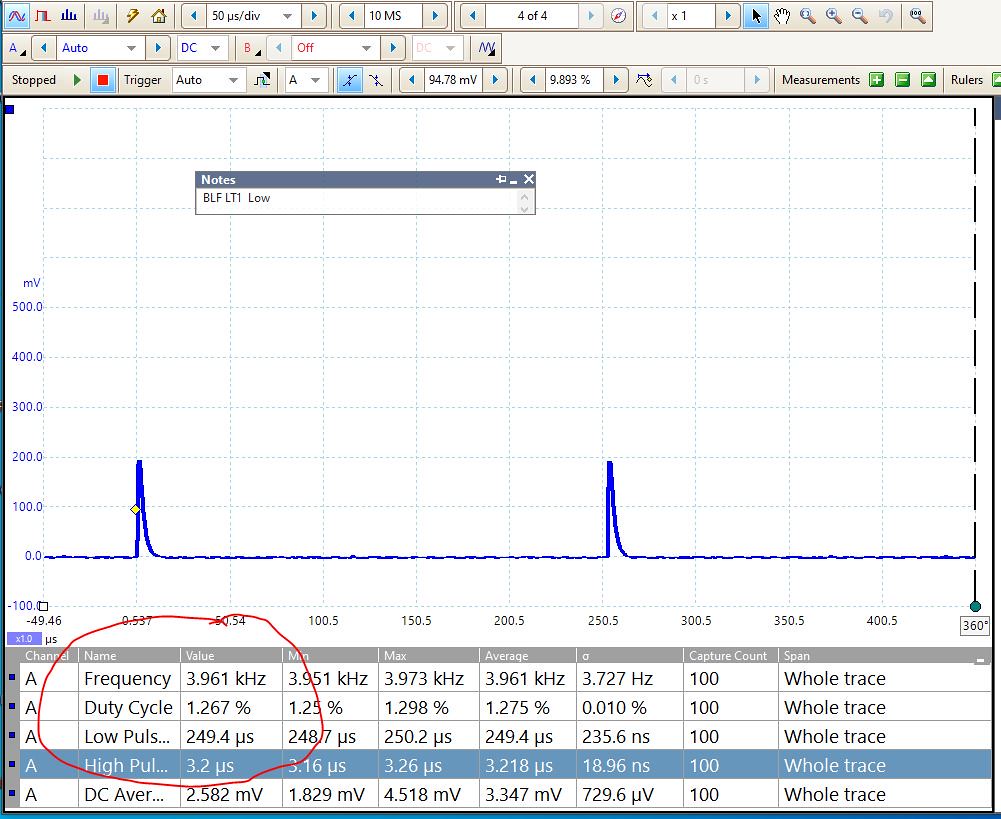
We see a PWM of 3.96kHz and a Duty Cycle of 1.27%

PWM Step 1

The PWM jumps to 15.8kHz, Duty Cycle 5.9%

PWM Step 2

Same PWM Freq. Duty Cycle increases to 8.4%

PWM Step 3

Same PWM, Duty Cycle 17.5%

PWM Step 4

Same PWM, Duty Cycle 32.9%

PWM Step 5 (High)

PWM still 15.8kHz, Duty Cycle 53.7%

Bring On The Tints…
Now things get interesting
Going to full warm color

Low - and a Mid step.
The Low and Mid Modes look the same.

Stepping up to Full Brightness

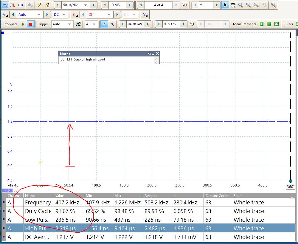
There is no PWM at all. The light is running a DC offset.

The same goes for all cool LEDs

Mid Step – and Full Cool.

But Wait – There’s More

Still on High,
Ramping away from all one color LEDs toward the middle tint
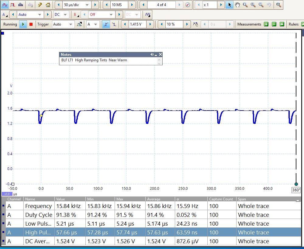
One set of LEDs is starting to drop duty cycle, and the other is increasing.

A Little farther away from the max tint

Farther Still

And in the middle of the tint range

The middle tint could fool me into thinking the output was just a Square Wave PWM (Foolish Boy).

Lots of fancy footwork going on to try to make the brightness even across all tint ranges.
Heck of a lot of thinking and code went into this, Thinks I.

Congratulations Dennis/DBSAR, TK, Sofirn/Berry, and the rest of the BLF crew that made this possible.
A standard against which all others shall be compared for many years.

All the Best,
Jeff

Awesome info !

Great write-up! Thanks for all the good info.
Any chance you could post the brand of USB analyzer you’re using? I have an old one that just gives basic info. It’s useful info but limited.

It’s something I got a few years ago. Turnigy brand, like the hobby chargers. I’m not sure if I got it on Amazon or Hobby Express.
It only has USB-A on both ends.

If I was going to get one today, I’d look at the more sophisticated ones that do USB-C and have more features.
I’d really like one that could be hooked to a PC for data logging.

I’m not really current as to what’s the latest and greatest version currently available.
Take a look over here:
http://budgetlightforum.com/forum/batteries/usb-power

There are quite a few threads discussing USB power meters and loads to test power supplies.

Thanks for the kind words,
All the Best,
Jeff

Hi Jeff,
Is this the Version #1 of the BLF LT1, without USB C-C capability?
Cheers,
~Gary

Mine has the Ver 5 on the board and the trim pot is a little farther away from the brass ring (according to the photos I’ve seen in the giant LT1 thread).

So I assume I’ve got the latest version.

The power supply I was using is supposed to have Quick Charge 3. USB-A output only.
With the USB power meter I use, I have seen 2a while charging something else. I don’t know what it does as far as protocols or pass through.

I used the included Sofirn C to A charging cable.
So I was looking for more that 1.5a that I saw the times that I checked the meter during the charging run.

I’d like to get a fancier USB monitor. There seems to be such a pile of them out there, many seem to be offshoots of the same thing.
Makes my head hurt trying to sort through them.
If you or anyone else has some suggestions, I’d love to know more.
All the Best,
Jeff

Jeff, thanks for answering my off-topic question, I’ll probably look for one like you’ve got as I don’t want to jump too far ahead until I figure out the older tech.
Also, fantastic write-up of how it uses PWM and some fancy programming to control the balance. I learn easier with visual information and your graphs are perfect.
Some folks are triggered by the very idea of PWM but at these frequencies it’s a non-issue unless you’re using the light for ultra high-speed video like a slo-mo.
Absolutely agree with your bolded statement at the end about this being a standard. With the enthusiastic gang here and a fairly responsive manufacturer I suspect future version will incorporate even more useful features and accessory options.

When I saw Matt Smith’s review, didn’t look like any visible PWM. Seems the fancy programming is achieving a good balance for the human eye. I have seen some people mention a faint detectable whine in a very quiet room, which I’m wondering is a sign of the PWM at work.

While lanterns aren’t nearly as popular as forward beam flashlights, I think this has been largely due to lousy execution by other makers. Most LED lanterns are relatively cheap and not well thought out. Anduril opens up a huge range of possibilities never before available in a lantern. The dynamic tint manipulation is such a fantastic feature. I’m really curious to see how this evolves and what will be in store for BLF LT2!

Yes, that’s the latest. V 5.0 versus V 4.3. Thanks again for your really terrific thorough review. I don’t fully comprehend the graphs but was able to pick out enough from them to remain impressed by the LT1 performance.

Super write up Jeff51!!!

Yep, I saw square waves and lifted an eyebrow too… but ToyKeeper obviously knows what she’s doing. I’ve read a couple of amendments from her re. this code and she’s tweaked it even more! Hats off to her for nailing this one for sure. :+1:

I wish there were a way to “mux” into the lantern (via the USB port) for firmware updates… but I’m sure many have thought this already. And of course, more code would be needed again. Still I see a future “stack” to allow this on future lights as USB charging becomes standard equipment more and more lately.

In just the last two years since I got into BLF and these lights… I’ve seen innovation move nicely forward compared to other technologies and it’s super cool to see it come from a collaborative source of “light freaks” who aren’t restricted to the frugality of the corporate driven model (where one guy right or wrong… is always “right”). As a former, professional marketer in high-tech (oh… ask me about USB!!!) I saw SO MUCH MONEY flushed down the drain by large development teams while one or two people actually won the day because they CARED about and LOVED what they were up to.

It’s cool to see that spirit here at BLF and manufacturers like Sofirn willing to work with them to bring it to market at a VERY fair price. The LT1 really is a LARGE step ahead of ANYTHING out there in MANY aspects for sure. I retired my WELL maintained and used Colemans THIS year replacing them with three new LT1s I am SURE will last longer than I do.

I believe you are correct.
Solid state electronics sometimes do make noise. I’ve heard SSDs in computers making noise when really working and the case was was open on my test bench.
Over on the 21700 light thread, zappaman mentions he has 2 Sofirm C8Gs, one sings, the other is quiet. Why?

On the LT1 the 3.96kHz pulse of the lowest brightness is well within the audible range.
The extremely short duty cycle perhaps adds to the possibility that something is singing inside the light.

Somewhere TK mentions using a light pulse to move fabric to look at modulation. I may be having a senior memory of this instead of a real memory of this…

The 16kHz PWM of the LT1 running brighter, is withing the range that some of us can hear (and by some of us I mean me 45 years ago, and those with doggie hearing).

= = = = = Time for one of my rambling rambles …

PWM can significantly affect the quality of light. Anything in the visible range can run from annoying to causing headaches and eyestrain.
I have measured lamps that have PWM in the 100Hz range (turns off an on 100 times per second). Simply awful.

Seeing PWM is as easy as starting with the light in a dark room and waving your fingers quickly in the beam.
A light with poor PWM will look like an old time movie, kind of stop motion jerky.
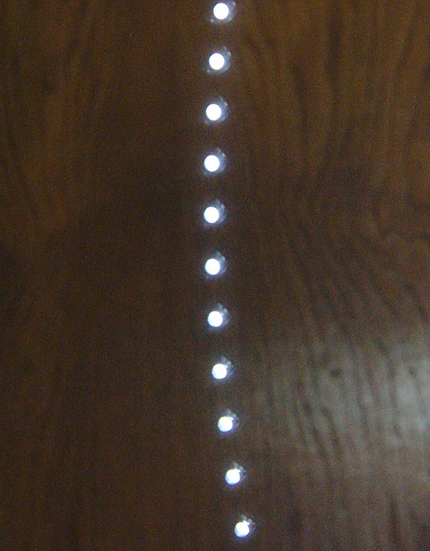
You can photograph PWM by setting a camera exposure to half a second and wave the light as fast as you can through the frame.
The light will show a series of blobs instead of a smooth streak.
For example here is the output of a Nitecore TUBE on low. A 500Hz squarewave, with a very short duty cycle.


As you can see the light is only on for a short period.

Another way to look at it is in the frequency domain.

Here we see amplitude plotted against frequency.
The main peak is at 500Hz. The PWM of the light.
All the other peaks are harmonics that are caused by the square waveform.
If this was an audio signal, we would hear the 500Hz tone, and all the other harmonics running up the frequency scale.

A wave of the light in front of a camera we see spots, not a streak.

So we are really looking a light that is flashing 500 times a second.

TK had a thread about it a while ago

Maukka (?) had a thread about rating a light in the “Snob Index” A combination of PWM, the Duty cycle, and the shape of the PWM. Approximating flicker visibility


The O-Scope shots, for any unfamiliar with them, are simply a plot of voltage vs time.
The voltage is generated by a simple circuit that uses an optical sensor that reacts quickly to changes in the light shining on it.
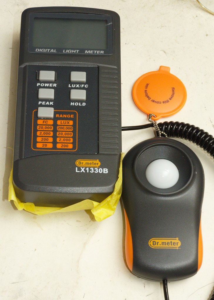
In my case I’m using the same OSRAM BPW34S that seems to be in many inexpensive Lux meters.

That the inside of the Dr. Meter and a shot of the sensor and the OSRAM photo diode.

In the LT1 - For example, the Low setting, at 0 time there is a pulse, that lasts 3.2 microseconds. Then the light is off - 0 volts.

Then looking along the horizontal time scale, about 249.4 microseconds later is a second pulse of light.
The Duty Cycle is the percentage of time the signal is above 0.

Looking at PWM is fairly easy to do if you are a little handy and comfortable making simple curcuits.
I did a series of POSTS about using a sound card to measure PWM.

This references other threads that lead me to my interest in this stuff. Especially the huge one by Terry Oregon that tested the response of various sensors.

Anyhow, enough of my ramblings. About scopes and PWM.
———-

The PWM of the LT1 is quite unique owing to the 2 flavors of LEDs and the PWM used to control them.
I’ll try and see if I can do a video which should show what’s going on better than the still captures I posted.

All the Best,
Jeff

Zappaman,
My feelings exactly!

And DBSAR/Dennis - I hope you are kicking Covids Ass.
Get well soon!

All the Best,
Jeff

I agree what you say about PWM, Jeff. Inexpensive LED bulbs for household lamps having visible PMM are money ill spent — where light is concerned, the eyes need to be treated as best as possible (most valuable sensory organ). I’ve bought a few T3 & T4 LED bulbs to swap in place of incandescent and they all have some PWM. Thankfully it’s only with notable movement that you can detect it. I don’t use them for reading, just ambient illumination in various places in the home, so no eye strain or annoyance.

So cool an idea to utilize sound for measuring PWM! I figured it wouldn’t be possible due to variances (i.e. some PWM being obviously audible while others quite muted).

With a sound card you are limited by the sample rate.
Many computer motherboards have 192K sound cards built in.
They are just never turned up to the max sample rate.

With a 44K card you can measure PWM up to close to nyquest.
Maybe 19K or so. But there are not enough samples to see the waveform.

With a 192K card you can see the waveform (sorta) up that high, and measure much higher.
Provided the software can deal with the sample rate.

With one of these it’s easy to measure the frequency of just about anything you will find in a flashlight.

The trick is not blowing up the sound card. They are picky about how much voltage they see before the magic smoke leaks out and ya’ got nutt’en.
Ask me how I know.

There are also some really inexpensive oscilloscopes on the market these days if you want to play with this stuff.

Once upon a time, some air force fighter jocks were tested. Some of them could identify an aircraft image flashed for 1/220 of a second (if I remember correctly).

I’ve found the amount of time the waveform is in the “off part” of the cycle is more important than the PWM frequency itself.

A 200Hz square wave PWM with a 95% duty cycle (light is off only 5% of the time). Is just fine.
A 200Hz square wave PWM with a 5% duty cycle (the light is on only 5% of time). Is inexorable.

House lights get away with 50/60Hz because they are not seeing a square wave.
The line voltage sine wave is not at 0 for very long during the cycle.

All the Best,
Jeff