Ok, It’s been a while but I’m finally making progress on this build again.
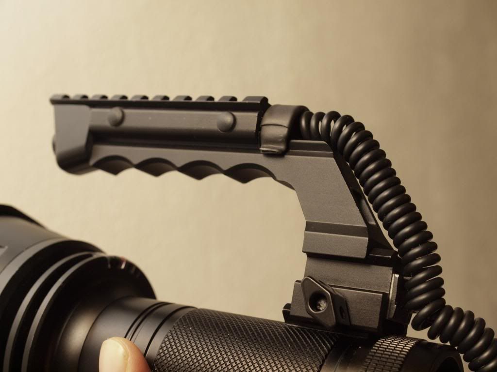
I’ve finally been able to retire the cable ties and assemble the proper handle mount!
This tiny rail part took the longest to get here and it was the first I ordered…
Original Ebay order went missing and had to reorder it from DX which took another month to get here, of course it also looks like a dog chewed on one end before it went to anodizing but hey you can’t have everything can you 
Anyway I wasn’t going to let this part hold up the build any longer, the battery tube is drilled and tapped and the mini rail is bolted firmly in place with brass M4 bolts.
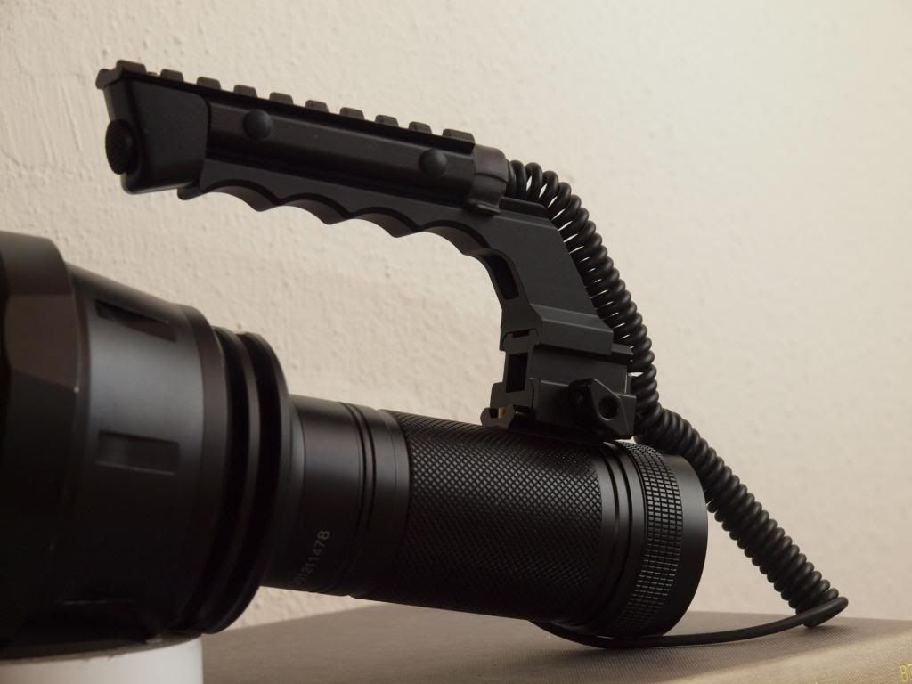
At least the dodgy end isn’t visible when assembled 
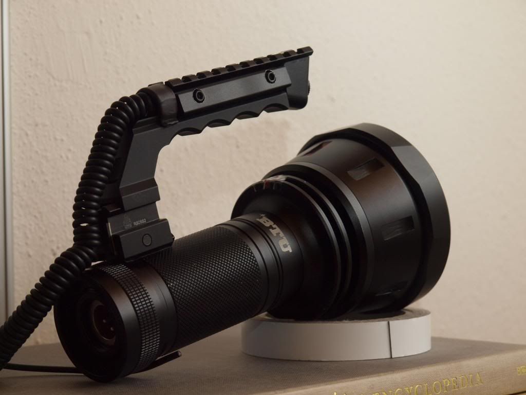
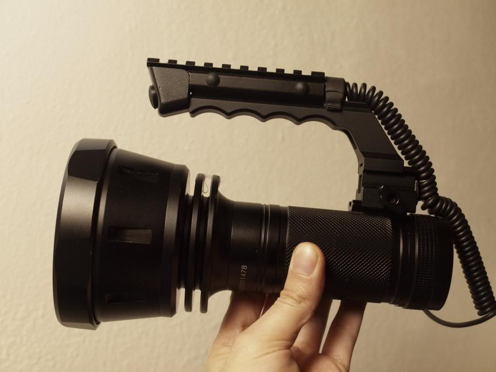
Very pleased with the handle now, it’s a fair bit lower to the light body than with the temporary mount and while I got used to that setup, this is just about ideal.
Haven’t tried it with the reflector in yet but balance shouldn’t be much different to before so that should also be fine.
—
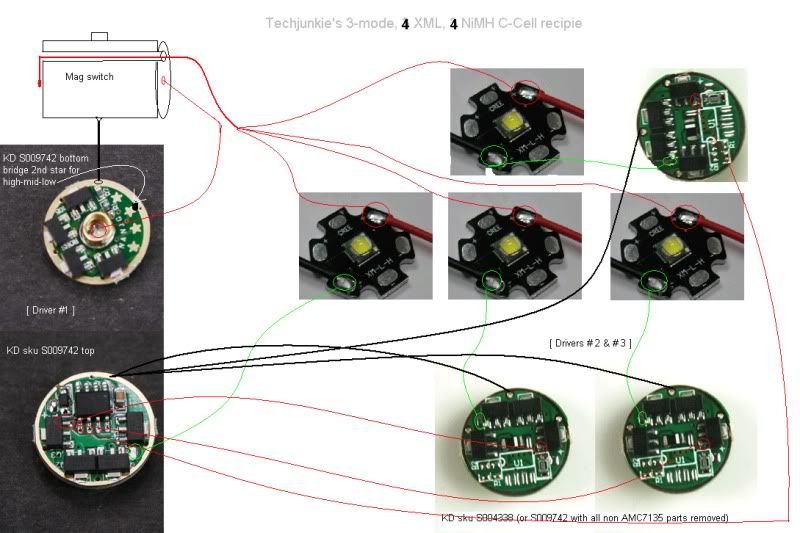
Next progress update is on the internals. These have been holding me up as well, but more due to their complexity than any missing parts.
The main problem was in transfering close to 20 amps through a turning interface contact to the driver electronics in the head, and doing it with as little contact resistance as possible.
This is what I’ve come up with…it’s still a WIP and haven’t tested it at the full current load but I’m pretty sure it will do the job nicely
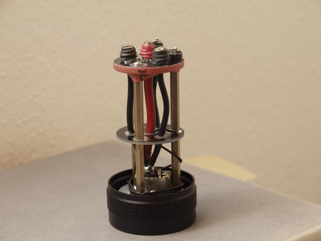
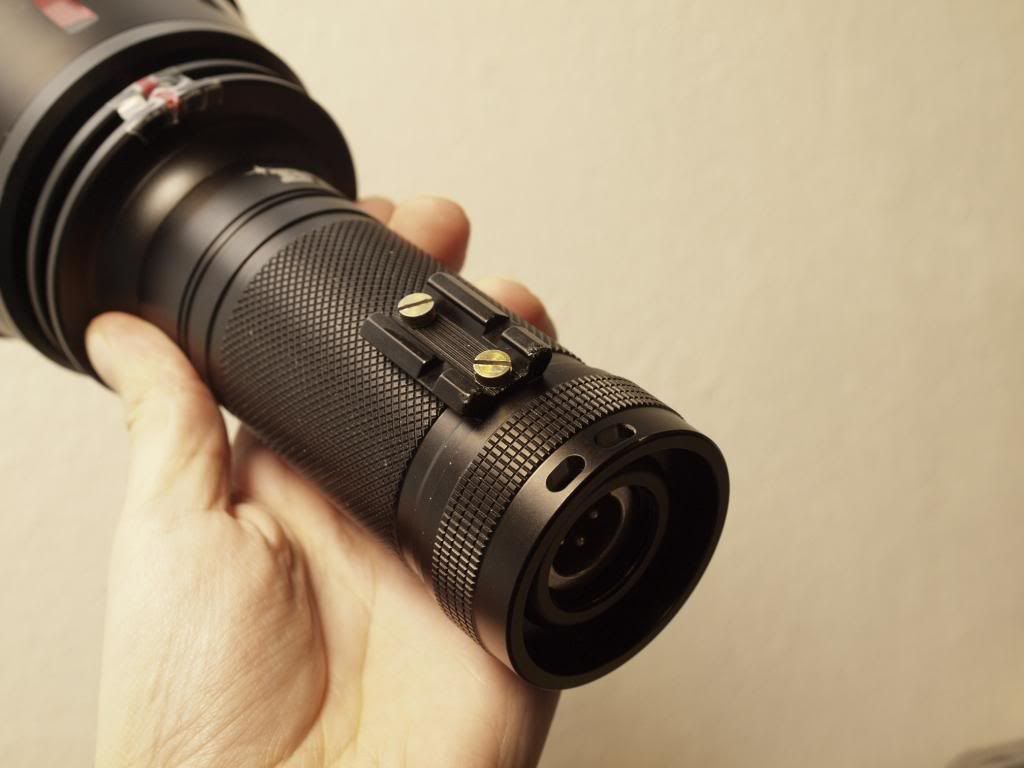
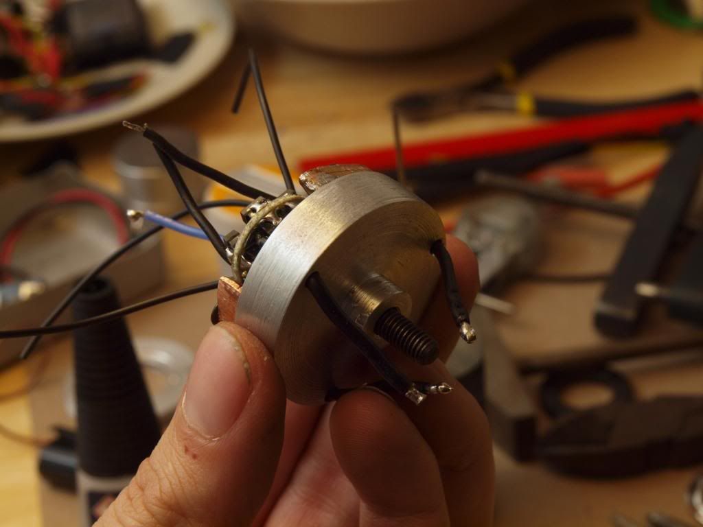
This is the reworked battery carrier, the xlr socket is firmly bolted to the tailcap case and the carrier assembly has been cut out and sunk around it then hotglued in place.
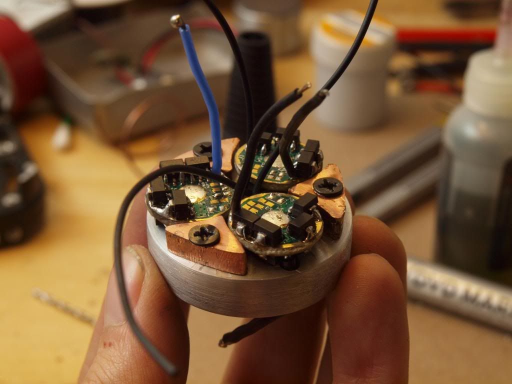
I also split the boards up to add one in the middle and increase the torsional stiffness of the assembly a bit.
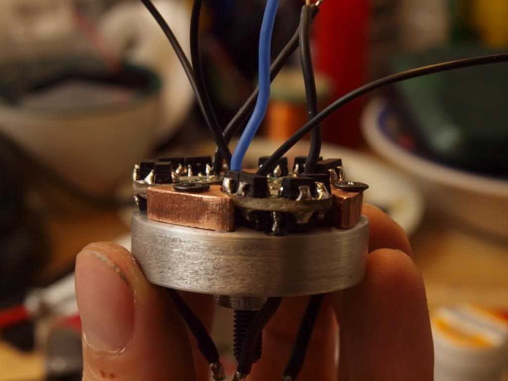
On the top I have 4 contact posts, these are made of fairly stout flashlight springs from cnqualitygoods and each one is heavily beefed up with copper wire to maximize conductance. The springs aren’t really very springy anymore but that’s how it should be, it just needs to make a tight press fit against the contact board without being too rigid and breaking anything off while being tightened.
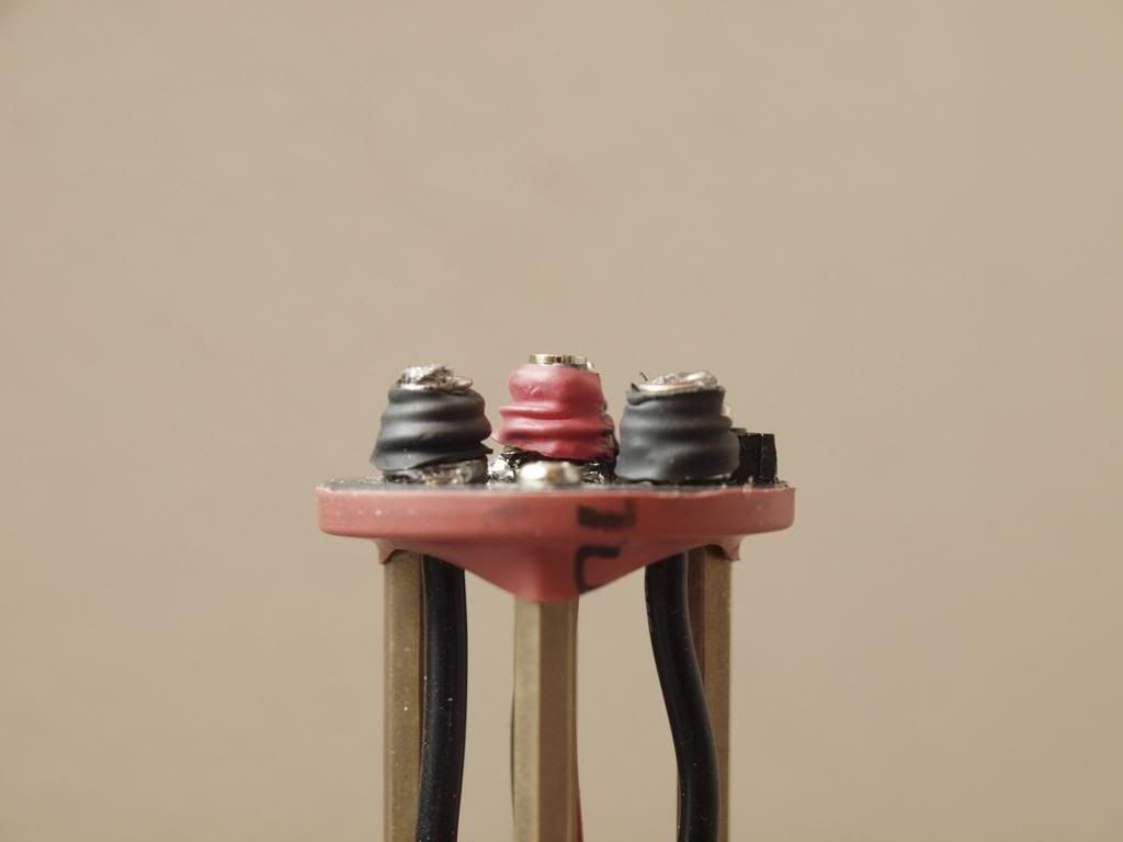
I have 3 springs/posts for the battery neg and 1 central one for battery positive.
This central one is even more heavily reinforced with copper wire and soldered to the top is a brass cylinder which will make the contact. It will also act as a registration and centering pin for the whole assembly.
Currently they’re wrapped in shrinkwrap to avoid any potential shorting issues due to bent springs, but I’ll probably go a bit further and glue a short plastic ring around the base of each post just to make sure nothing can jump across and short.
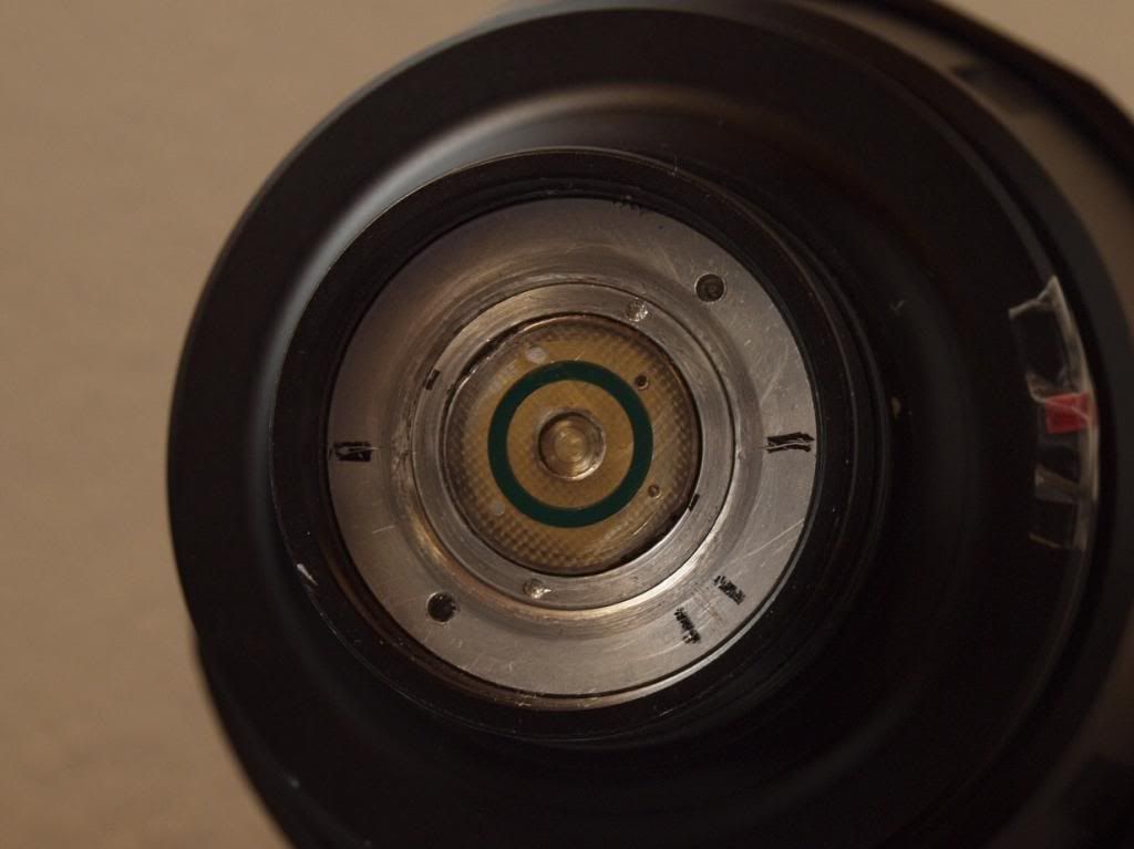
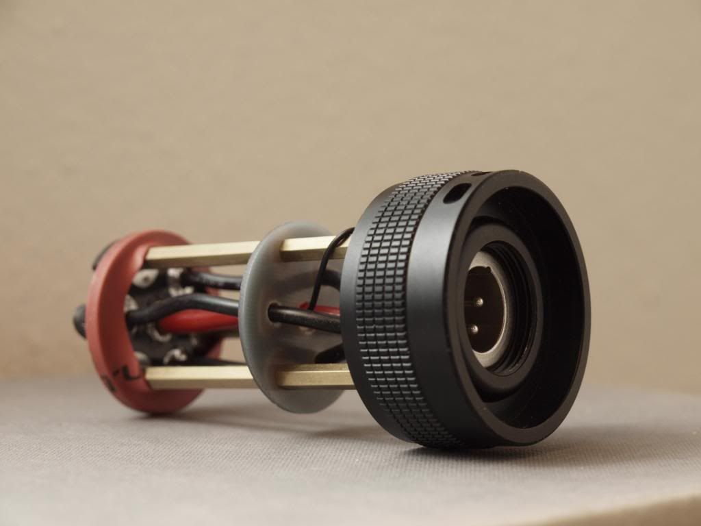
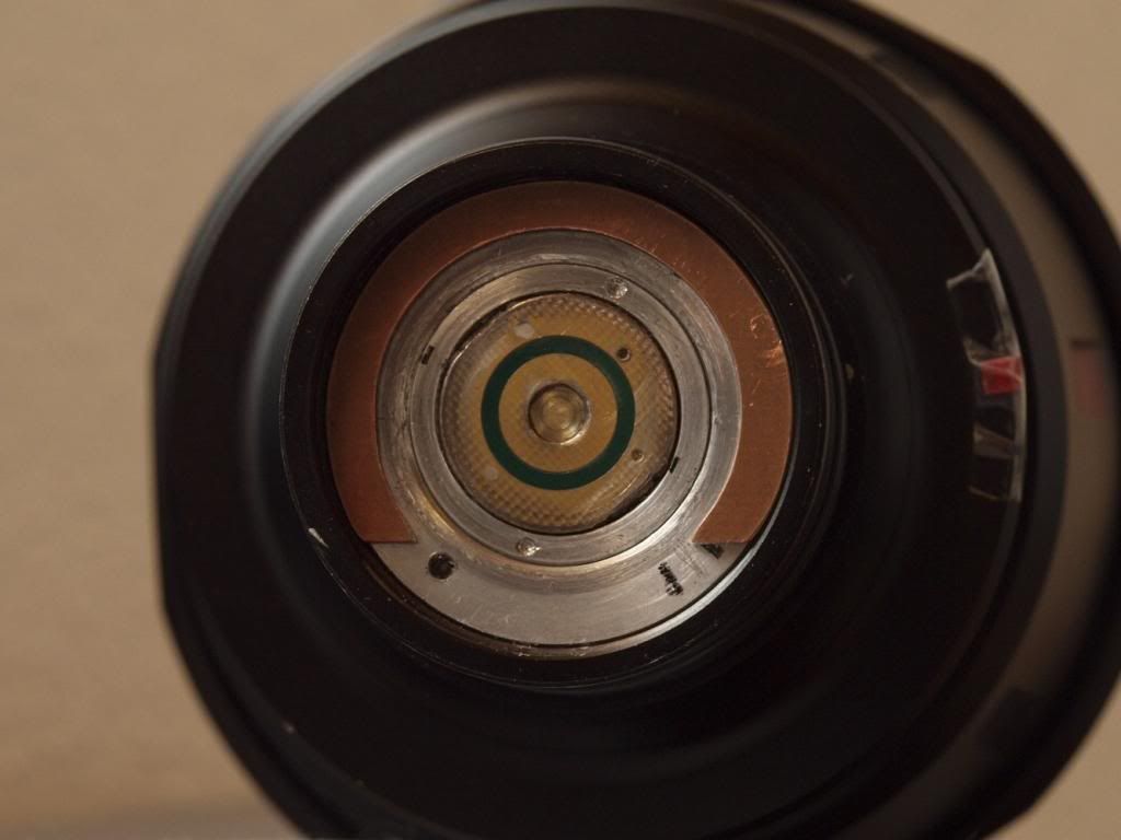
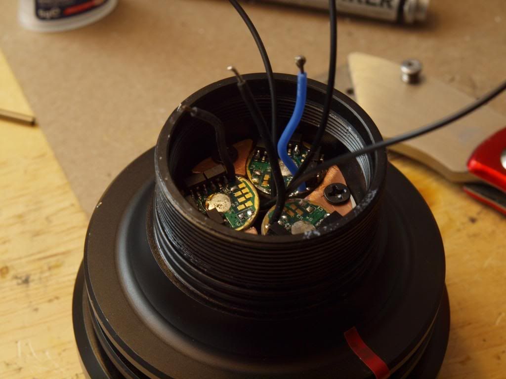
On the opposite side I’ve reflowed a 20mm contact board to a copper wire extension so it could be clamped into the stock driver retaining ring, then soldered another brass cylinder into the central hole with a small depth offset to which the main battery positive wire for the driver is connected.
The small cylindrical recess created in the center offers a registration/centering point for the battery positive contact post as well as hopefully a good tight contact surface.
You can see the polish/wear marks from the negative posts on the aluminium edges of the contact board, I’ve tested the tightening of the assembly over 50 times while working on this thing and it’s doing very well. You can hear the click as the “centering pin” battery positive post engages with the contact board and then it tightens smoothly but with a healthy pressure resistance all the way up to the end of the threads.
The final part to this twisty puzzle was how I would complete the circuit for the clicky trigger switch in the handle. This needs to deliver or interrupt the power going to the MCU side of the driver and therefore needs it’s own contact post/surface combination on the contact board.
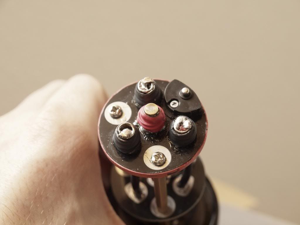
My current approach for this…and it’s not done/working very well yet… is using a spring loaded little contact post on the battery carrier side (made from a cheap 3x AAA battery carrier) and a circular copper contact surface made from a pcb board material on the contact board side. At the moment the contact surface is just too wide and interfering with the battery neg posts but I can probably work it down some more. It’s also a bit too thick so might need to find some thinner pcb board material or try something else…
An alternative that might be simpler is to go with a magnetic reed switch approach, tiny reed switch glued to the outside edge of the contact board or even behind the contact board? And a coil connected to the trigger clicky on the battery carrier, positioned where I have the spring loaded contact point assembly at the moment…
…so if anyone has any thoughts on if/how best that could work here please let me know. I don’t know enough about reed switches and coils to know if I would even be able to generate a sufficient magnetic field in this type of setup.
In any case I’ll do some load testing of this setup soon and if that passes without a fire I’ll finally move on to installing the critical components!
—
A simple test assembly has convinced me that I need to at least drill a registration pin hole into that damn reflector and add a pin to the emitter shelf so that it doesn’t all twist when assembling the head. I also need to add some handles or something onto the reflector so I can lower it into the head precisely without fear of dropping that damn thing on the emitters! Not to mention aligning and drilling the emitter wire holes and potentially pcb screw holes will take a lot of patience…
I also have my copper spacers to heatsink into the reflector done and waiting but that’s another variable that needs to be accounted for when laying out and assembling it all…this whole part should be a lot of fun if I prepare it all properly…but I’ll also be really glad to see the end of it for sure!!
Cheers
 .
.