subbed
Hm, I hadent paid attention to the ears, one thing I’ll need to verify is that the cut’s for the tabs are at the same location in every different variation of host. I may have to end up not doing them, since again there’s only gonna be one way the driver can be orientated cause of the cell conversion.
I’ll be getting a couple more Courui’s from the GB deal, so will be able to compare the cut out location. Unfortunately, they probably are a few weeks off yet.
Even with the driver in a fixed position, won’t we have to make sure the battery tube will end up in the same position when screwed on?
edited- changed ‘BG’ to ‘GB’…
In my experience they always end up within one degree every time you tighten them back down, maybe a different location than with the original board but I’m willing to bet it’ll work once we get it figured out, it’ll also probably be different for everyone’s lights.
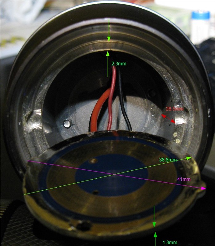
Hopefully the pictures here give you what you need.
That was my concern.
The 'ears' on the driver are at 90 degrees to the hole for the switch. ( & I'll bet that will be the same for all of them).
:beer:
Very useful, thank you.
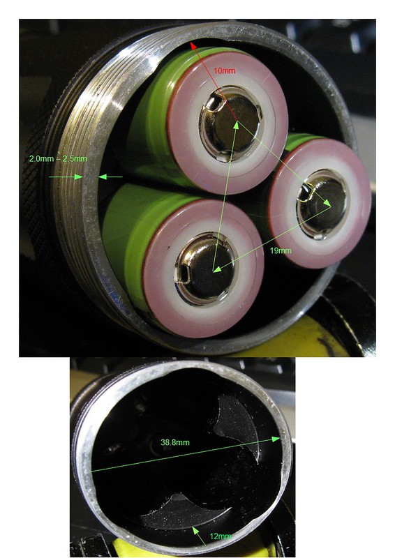
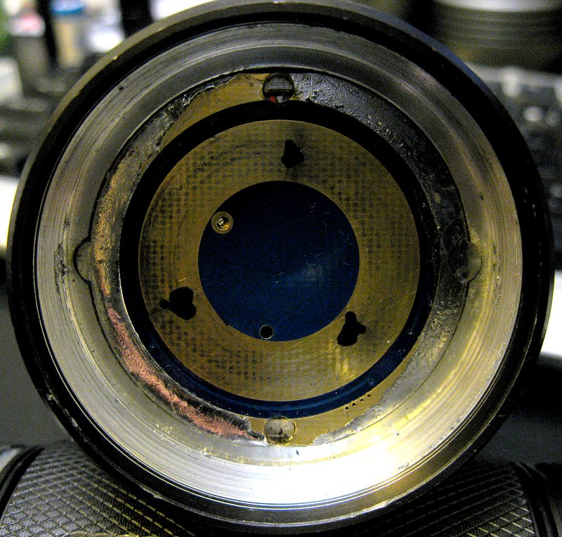
One more slightly more in-depth request, could you please remove the tail. remove the Batt- contact plate and then screw the body onto the head (with driver installed) and mark the position of each cell’s + button on the bottom of the driver? (I’ve done this by using a drop of fingernail polish on the button, it’ll transfer leaving you an exact position mark)
I’ll get a picture up of that tonight for you.
I’m guessing that your design is going to have one (or more) separate battery contact points on the base?
The only way I can see that working is if the driver was fixed in the correct orientation for each individual head/tube combination, which would be relatively easy, using the existing cut-outs in the shelf for screw-points.
As requested;
Ive got my circuit designed for the power cutoff using a P-FET, I have selected a large, high enough rated P-FET to be able to supply all the power to the entire driver /load but I’m wondering if I need to do that or if I could use a much smaller rated (and package) FET to ONLY cut power to the MAXUM chip?
That would be ideal, but unfortunately it’s not practical because of the high-side current sense on this chip. If you look at the circuit:
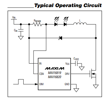
you can see that the chip is measuring sense voltage between the Vin and CSN pins. If you put a FET in front of Vin, you’d have a voltage drop due to the RdsOn, so the voltage the chip measured would be lower than the actual sense voltage, meaning it would skew your current setpoint up, possibly by a quite significant level, and even worse it would be unpredictable due to FET drive differences and Vbat changes.
I might try that diode you posted in the op- Vishay SL43-E3/57T
Put that on a yezl and see if that helps me run 3s over 6a with the stock driver.
The datasheet says 4A when mounted on FR4. Why not pick something actually rated for what you want to do?
Your right just read the datasheet… Well he said 8a in the op
Yeah, I just went back and read the OP again (as you were posting this) and realized that my comment would have been better directed at tterev3 than at you!
Well then this TK61 driver is owning me right now.
I have the components (10f322, DPAK P-FET, 2 cap’s) laid out and connected in the .sch but when I cut the Vin to MAX16820 and route it threw the P-FET and switch to the board somehow there is an airwire going from Vin to GND I do not understand. I had to walk away last night after looking at EVERYTHING.
Will try again today.
Nets don’t connect to each other. So I suspect that there is not actually an airwire fron Vin to GND. Which net does the airwire say it’s on? Get the Properties or use the Name command on it.
After I do this and I click on what should be the GND via it’s name is changed to VIN and there is an air wire directly from the BATT- to BATT+ via’s, further trying to change its name (on the board) back to GND also changes all of Vin’s names to GND so they’re definitely connected.
Note I’ve stopped making large GND net’s, instead I use individual GND points in the .sch and I let a GND plane (poly) connect them all on my board as the very last step.
-
When I get to it today first thing I’m gonna check is the pad/pin names of the P-FET I made, if that isn’t the problem I’ll come back here for help. -
Side note: you’ll be happy to know I’ve started minding Ratsnest and DRC/ERC!
edit: today it worked first time, deleted one net, moved 2 others and worked perfect. I’ll attribute it to trying it at 2AM after a LONG day…
You’re right, I was picking example components just by looking at the data on the Mouser product selection page and never checked the datasheet. I’m surprised and frustrated that this manufacturer would put their MCPCB rating into the database!
I’ve been assuming that Mouser has people employed to do data entry. I assumed that these people glance at the datasheet and then hammer some numbers into Mouser’s DB. That’s who I’ve been blaming for things like that, heh.
Anymore stuff on this driver? I know it’s over my head :bigsmile: but I’m kind of excited about a programmable buck driver.