Ever since I first saw the chopped Minimag in EDC’s avatar I have wanted to make one, even if it wasn’t as perfect as that. Since then I found that 2 members here have made an art form of this mod and the M&M is named in their honor, Match & JohnnyMac. Over the past few months I have been reading over and over the build and for sale threads for each of these that I could find and decided to try and make one for my 1K giveaway. I am quite happy with the results and learned a few things along the way that I’d like to share.
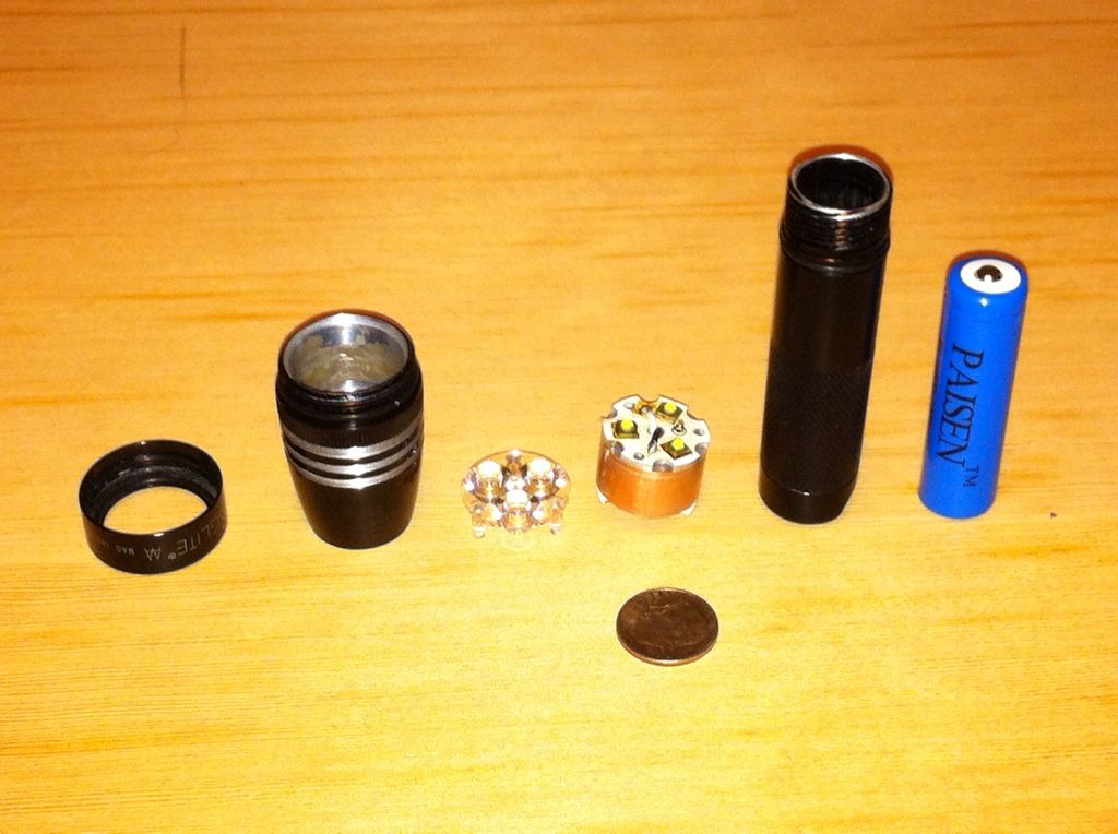
For me, the first step after disassembly was removing half of the male thread portion of the battery tube. This was done by first wrapping the tube in blue tape and then cutting it with a radial arm saw(old Ryobi 8” model with carbide blade). Overkill I know but it’s what I have This allowed me to then enlarge/deepen the reflector hole to the point that the remaining male threads would reach just above (1-2mm)the new “step” when screwed in all the way. My method for this was to drill a 1” hole all the way through a 1x4 and 1/4” into another. The AA mag head is a snug press fit into the top without bottoming out in the lower piece. Drilling the head was done with a 3/4” hole saw on the drill press with plenty if lubricant and frequent removal of shavings. This creates a flat bottom step rather than a bevel from using a standard bit. I realized later that by increasing the set of three teeth equally spaced around the hole saw I could effectively increase the drill diameter a bit(set is the alternating bend of the teeth on some cutting tools). For this one I finished it with a dremel and then a 3/4” dowel wrapped with ultra fine wet/dry sandpaper. Once that was done, I could measure the depth and creat the pill.
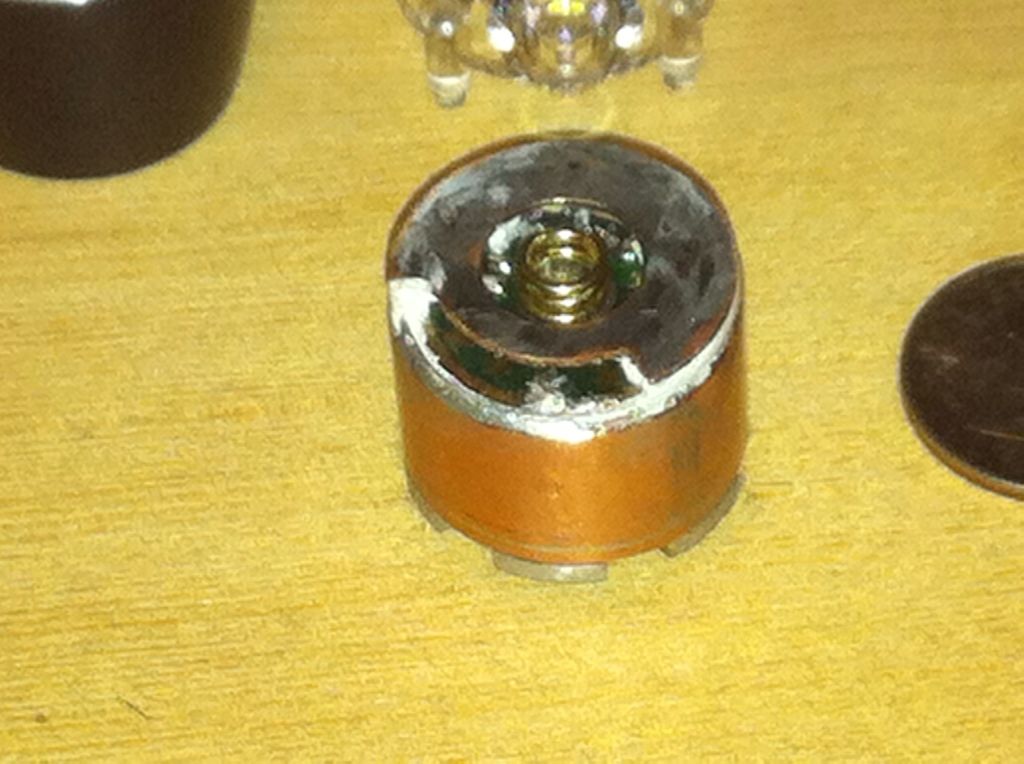
The pill was made with my usual method of sleeving successive layers of cu tubing or cu sheet sized to need. I keep repair coupling which comes in 12” lengths rather than the short pipe couplers as it is easier to hold and cut small pieces from a much larger one. Also, 1/2” coupler is ~1 mm larger od than the 105C driver I planned to use. A piece of 1/2” pipe 2mm shorter to allow for the chip height went inside of this and a piece if 3/4” pipe, cut and resized to fit snugly around the outside plus 2 discs cut from flattened coupler stock (heavier guage than the sheet stock scraps I have) completed the parts for this part if the pill. Once soldered together, they were filed and sanded until the pill was a snug press fit into the head.
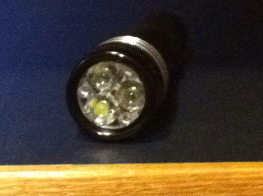
Because it has chips on both sides the 105C driver has only a narrow ground ring which is inadequate for this build so I cut another disc of thin sheet stock this time and drilled holes in it matching the 3 vias in the ground ring of the driver. I plated this on one side with solder using a 200w iron (gas stove and a soup can lid works as well) and then redrilled the holes through the solder. 3 pieces if thin guage solid cu wire were then soldered to the driver vias, AA applied to the tops if the 7135 chips on the spring side and the now plated disc threaded onto the 3 wires and clamped to the AA topped Chios. Once this had set, the wires were quick soldered, cut, and filed down smooth. A portion if the disc covering the stars was removed to allow mode afterwards. Wires were then added to the output side of the board and after trimming and tinning them it was fixed into the pill with Fujik. After installing the LEDs, they would be sinked to a pill that did not have direct metal to metal contact with the driver. The heat path for the LEDs flows through the pill and into the head but the path for the chips is through the plate to the battery tube. It may be moot since they are so close together but that minimal separation may help maintain driver operation.
I operated on the tail cap next by removing the portion above the threads and soldering a plated spring to a short piece of cu refrigerator tubing that press fit into the center hole and then ground off all the threads but for a shallow line showing where they had been. Holding the now thread less tail cap in the the battery tube I dropped in 2 cell to see how much stuck out the other end both compressed and uncompressed. Allowing for the positive spring on the driver and compression of the tail cap spring, I taped, marked, and cut the battery tube so that when off the battery did not rattle, and when on, the springs were not fully compressed. Then using a dremel, I reamed out the battery tube until the the tail came just short of seating fully. I put the battery tube on the soup can lid on the stove at very low heat and put the cap in the freezer near the fan, made up some JB weld, and put some tape on the vise jaws. When it was mixed I put on some gloves, took the cap out of the freezer and filled the groove where the o-ring had been with JB, dropped the cap into the battery tube and put it in the vice for a nice warm hug. I wiped of the excess and wiped it again with brake cleaner to remove any residual epoxy in the knurling and set it aside.

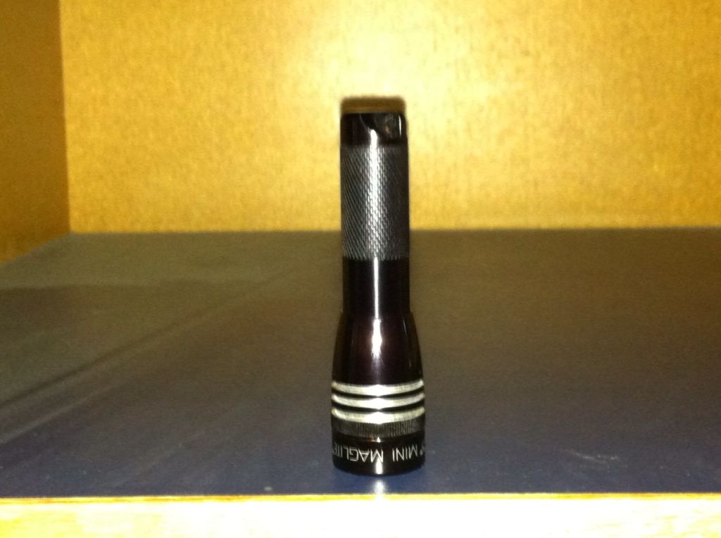
I had often wondered if it would be possible for me to do fins and recently came up with and idea I thought might work. I don’t have a lathe or Justin’s steady hands but I have a small drill press with a hole in the center of its table. When making the brass sleeve for the solitaire I found the bolt fixed only into the church wobbled producing a cut of uneven depth but was able to eliminate thus play by using a longer bolt that went clear through the work and the table with a bushing in the table to stabilize it. After that, the block of wood with the hack saw attached worked extremely well and I’m confident that with a bit more practice I’ll be able to do more passable work. The pictures show neither how good nor how bad my machining is and while not anywhere near good enough for saleable work, I think it just fine for friends, family, and hobby work. DIY indeed.
I can’t wait to make one again! Thanks for the read


