Building a F6DD Triple (Roche/Convoy/etc.)

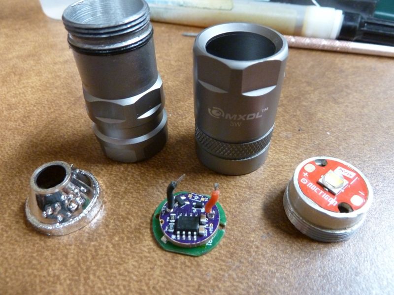
STEP 1: teardown/measuring

H1 + H2 is 0.464".

H1 +H2 +H3 is 0.743".

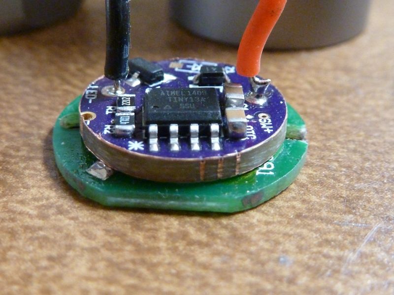
These digital things are so awesome. So you can do it the hard way, measuring and writing stuff down and then using a calculator, or just use the zero button.

Measure to point A, zero, measure to point B, and the display is the difference between just those two points. No calculator or scratch pad required.

Dimension of H3 is 0.280", this will need to be filled with an aluminum plug later.

Here's that zero button at work again. Measure the part you don't want included, hit zero...

...and you get the measurement of the parts you want, with the part you don't want left out.

So, the stuff that has to fit inside is 0.484", but the distance down to the bottom of H2 is only 0.464". If you put it together as-is, you get this:

There's another problem that shows up when you check the IDs.

D1 (at H2) is 0.839".

D2 (at H3) is 0.661".

But the 3XP board is 0.790".

That means there's nothing to center the MCPCB with the bezel opening, since it can flop around by 0.040" in whichever direction it feels like.

To make it all fit together properly, I'm going to: Press in an aluminum plug sized 0.662" x 0.280", face the top surface of the plug down to a depth of 0.480", and a diameter of 0.792". That will put the bezel around 0.003" from bottoming against the front of the head when gronked down really really tight, and center the MCPCB well enough but without any chance of binding against the sides and not making good contact with the plug.

Coming up next: I BOUGHT A LATHE!

--------------------

Non-off-topic posts:

Post #8: Mounting the head in the lathe chuck

Post #13: Making the press-fit plug/spacer

Post #12: Adjusting for zero runout, machining the shelf

Post #66: Cutting threads for the screw-in tailcap plug conversion

Post #70: Making the new threaded brass tail plug

Nice. :beer:
How did you remove the button? Was it hard to do without damage?

First step is to push the clear plastic lens out from the inside (I use external snap ring pliers - expand when you squeeze), then use that as an access hole for a punch to drive the switch parts out. It's not that tight, no Loctite on any I've found so far. Use the biggest punch that will clear the hole, .200" is about the max, to spread the load over as much of the rubber button as possible.

Just curious, can you see how the battery possitive could short out when using long cells? Or does the little white plastic washer keep the copper driver button from being fully compressed? Idk… Does my wording make sense? I ask because I had a cell short out on me while modding to rgbw. I think the tail spring I added was stiffer than the driver spring and thus caused a short. Made my Sanyo 18650b get quite hot! :-/

The center contact will press clear through the backside of the retainer, only the spring stacking solid or the button hitting the driver will stop it moving forward. The plastic insulator also presses out the same direction. Button top cells are not a good match for this design, especially if the button is larger diameter than the plastic insulator.

Shorting the cell to ground through the brass retainer should not have had any effect on the driver. It's downstream from where the short happened. Either there was some unrelated driver problem, or the short wasn't where you think it was. There should be some visible evidence of arcing somewhere, go find it.

This should be good! I’m surprised and happy to hear that, I look forward to your no-BS methods being applied to the lathe.

A digital depth gauge… what’ll they come up with next! Honestly I can’t believe that I don’t own one of these. Is there any particular reason I shouldn’t just run out and buy the cheapest one I can find? Should I snoop around auto parts stores for the best price or just go straight to the Chinese sellers?

There are US sellers. I got a 2-pack for $10 delivered. Search for 'digital tyre depth' (no, I don't know why even the US sellers spell it 'tyre', I suspect it's copy-paste syndrome).

PART 2: I bought a lathe (and I'm not afraid to use it)!

I spend 80% of my time making tools used to make another tool that eventually (maybe) results in being able to work on the actual item. Like this thing:

You can buy ready-made ones, but I've only ever seen them in steel, not aluminum, and they all have the screw going in from the front, which doesn't work very well when you can't get to it because it's covered by the part you need to stick on the end. They're called expanding arbors, internal collets, etc.

Slug coated with thermal grease and pressed in (and it's tight, it isn't coming out unless you use an endmill):

Starting dimension for the depth is 0.456" (target is 0.480").

Hit the pause button, I have some lathe-related junk to explain first...

Ok. I couldn’t remember how the retaining ring and contact functioned before I modded it. I took a dremel and hollowed out the retaining ring to fit some more chips so I thought that might have had something to do with it. The best I can figure is that the button top of the battery shorted strait through the retaining ring. There is no evidence of arcing though.

After the incident I tested the driver and it didn’t function. Idk if it was related or not? I replaced the mcu and it is now working great! It was a lot of work though. The f6 does not have much space for working. Your design should be easier to work with…Small FET and spacer for leds.

I’ll keep watching. The f6 is a fun little light. And now a fun little BRIGHT light :wink:

comfy - very interested in following this! congrats on the lathe!

This F6 looks like the old style no longer available? I have two F6's and both don't have the window on the backside from the switch any longer. On one I modded, I mounted a light pipe next to the switch to let the light out, but it's not in a good position with a small diameter light pipe, so not much light gets out.

I'm really into modding tube side switch lights, and was lucky to grab a couple SWM C20C's on a heavy discount ($30) at illum.com before they sold out. The C20C is a F6 look-alike (or the F6 looks like the C20C?), but is smaller in length, has a better tail spring, and doesn't have that PIA removable SS plug in the tail. Of course there's a few differences of pros/cons but it's very moddable, and the shorter length and lighter weight gives it advantages.

The C20C is still listed available on FastTech, but not cheap @ $42.41, and most stores have obsoleted it, while the F6 is 1/2 the price.

Calvin still has the SWM C10R (1 CR123A) version of the C20C, 9 pieces left at a great discount at $25 each.

I know all the arguments for and against 3 jaw scroll chucks vs. 4 jaw independent chucks. So I decided to do this:

That's a cheap $80 5" chuck, on a homemade adapter, on a Grizzly 7x12 lathe. The adapter fits loose over the OD of the spindle flange (by about +0.050") so it can move around. With the four M6 nuts lightly snug, the adapter+chuck can be moved around on the flange and adjusted to zero just like a 4 jaw independent chuck. Your cheap 0.003" runout chuck just became a 0.000" runout chuck.

(The chuck has also been converted to front-mount, for anybody sharp enough to spot that and say 'whaaa...?'. The rear bolts didn't cooperate with the dimensions of my adapter and where the adjuster screws needed to go. It's super easy to do, just drill all the way through from the back using the original rear-mount holes as a drill guide, then make a counterbore on the front for the capscrews.)

F6 head, mounted on the arbor, ready to be zeroed out:

Test indicator is reading the ID at H2 (see first post).

Before adjusting, I read about 0.006" runout (note: the chuck was not re-adjusted to zero with a known-round test bar before starting, so the arbor setup may have been less or more than 0.006"). About 2 minutes later I was reading this for the low spot:

...and this for the high spot:

Showing about 0.00025" or thereabouts. The needle was moving more from the surface finish of the ID than from actual runout.

I'm using an internal threading tool, but with a plain TCMT insert. It's not really a boring bar but the metal doesn't know that, so it's OK.

So did it work?

Close enough.

Still yet to de-bird the center hole and polish up a little.

I used a spare 3XP mounted on one of my handy patented* hot glue stick handles as a go-nogo gage, much better than fighting with calipers while still in the lathe chuck.

*(not actually patented)

And the nasty ~0.020" gap under the bezel has magically disappeared.

Oops, I left out the making of the aluminum plugs.

Started with 3/4" 6061, about 6" long. Turned half of it down to 0.662", took it out of the chuck and flipped it around, re-zeroed the adjustable chuck adapter, and turned the other half down to 0.662". I can't even find where the two ends meet in the middle.

I marked off sections of .280/.065/.280/.065/etc., parted off the pieces. 1/16" parting blade. (yes, parting one-handed while taking a picture. I thought this was supposed to be hard?)

This is amazing work! IDK how I’ve been here for 7 months without noticing some the the work you have done. I did some searching to find some great build threads. Most are one or the other, but you are both quite knowledgable and skilled. I guess this is why it seems others are not surprised with your efforts on this f6.

My favorite light right now is an Olight s30 modded with a 20mm Blf dd loaded with mobydrv firmware. I added a switch, potted the driver, wrapped it with aluminum flashing, and press fit it back into the head. The driver modual ended up being 6mm or so. And befor I replaced the driver module, I press fit an18x5mm slug to fill the driver compartment with some mass. There is much more room in there than the Roche. It does 5amps with a 30Q on turbo. It gets hot, but the output doesn’t sag too much. It is set up so that a tap turns it on in the last used mode, press for low, and double tap for turbo. By far this is my favorite UI and the s30 is a great host!

I've done pretty low profile sandwiched drivers, like this I did in a pair of $5 MXDL 16340 twisty lights:

For these, it's just solder blobs making the contact for batt+ and ground. It can be done, it's not easy, but...

Should wait for comfy to get to the electronics part of this project. I'm think'n he'll use Halo's OSHPark board. He's built a triple F6 for TK already using the Halo board, and I used it as well. I'd prefer a FET+1 design, but don't think we have one in this form factor.

Tom, do you have a Shadow GF2 or ever seen the innards of one?

We need to form a union, and let whoever makes the F6 know that we're going on strike until they go back to making them with the battery indicator window. Oh, and also that they should sell them to us in host form, in bulk, for a big discount. Or else! (shakes fist in the general direction of China)

+1 . No, dunno the GF2 at all. Think when Convoy (Simon) got involved, at about that time the window went away. I drilled a hole in my windowless F6 and inserted a light pipe (bought some from Mouser and DigiKey in various sizes). Choices on sizes is not so great though.

I'd make them fix that dumb tail assembly as well. The spring can't be soldered to (no conductive coating), and that SS cap comes loose and is difficult to secure. I jammed alum foil in mine and it's kind of/sort of holding. For the spring, I used a bypass wire, but wrapped the wire around the spring wire and soldered it, so it doesn't hold well to the spring, but as long as the wire touches the batt- and contacts well to the body, it sort of works ok.

I like all the hoopla and goins ons with the lighted tailcap efforts - an MCU controlled SMD LED works sooo much better in e-switch lights. I got some nice firmware now to control an ON/OFF LED via pin #3. I've added the support to my Narsil firmware (requires the 85).. Blinking out the battery voltage level for example, or using it as a locator w/some drain of course. But in my firmware, you can configure it's use as a locator to be enabled or disabled.

The tail plug... thing has green Loctite (or a knock-off version) on it, all the ones I've taken apart. I also haven't had any that were loose.

I have pics in the old F6 thread of what to do with the tail spring. I cut the largest coil off the spring and fit it back into the groove to act as a filler, and use a beefy spring soldered to a copper disc. I use a little Hypo cement around the bottom corner of the stainless plug to hold it in. The ground happens between the copper disc & tube, the stainless plug just holds it in place. Output jumps by about 30-35% just from the copper disc/spring change with both single LED & triples. That stock spring is nothing but a shitty resistor.

Yea, I saw tremendous loss’s in the tail spring as well. I think the bypass wire got most of it back. Hhmm - I probably saw your mod on the spring - great idea. Dunno what happened with my 1st F6 (also no window), but once that SS plug got loose, it would not keep tight - it used to go popping out on me all the time because the tension from the spring, up until the layers of alum foil solved it.