Built a custom boost driver, trying to figure out solution to audible noise

Hello everyone,

Long time lurker here, finally making my first post!

TL;DR: I built a boost driver, and can hear an audible whining noise at medium loads. Any tips would be appreciated!


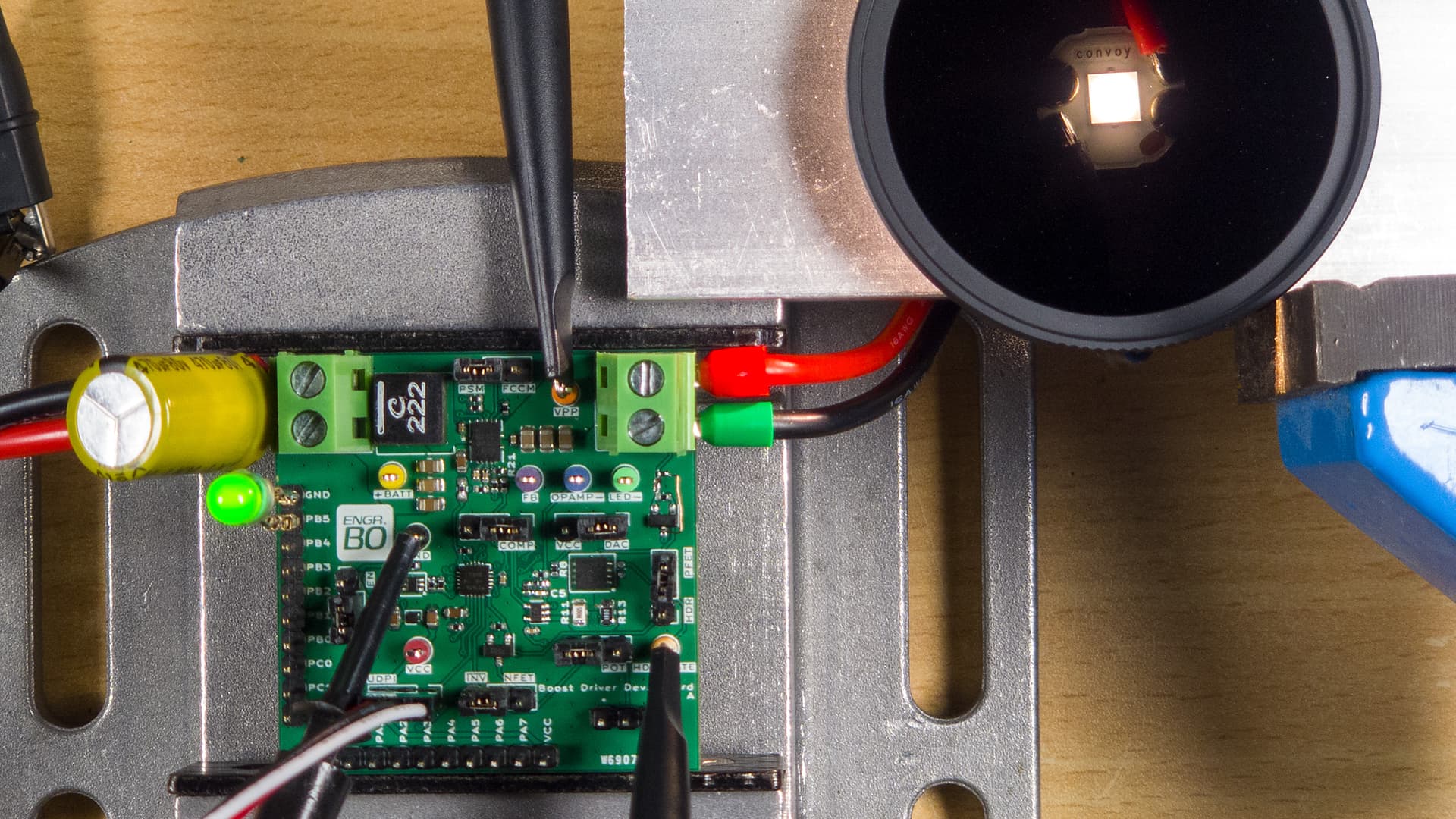
Boost driver dev board driving XHP50.3 HI (under 10 stop ND filter)

I’m on a quest to build myself a flashlight, and my first step was to answer a bunch of questions I had about boost drivers. To do that, I’ve made myself a dev board with some of the more popular components:

  • ATtiny1616 MCU
  • MP3432 boost converter
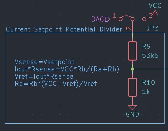
  • Current control with op-amp (TLV333), setpoint using ATtiny1616’s DAC
  • High dynamic range (HDR), technically ~1000 unique brightness settings
  • Output is set to ~6V for an XHP50.3 HI, hardware configured for ~4A max
  • All the usual features: battery voltage sensing, temperature sensing, off-time estimation etc.
  • Setting current setpoint using external potentiometer
  • Custom firmware for testing e.g. ramping brightness up and down on loop, dynamic VREF etc.
  • Jumpers everywhere to try different things

Over the past couple of days, I’ve managed to answer several of the questions I’ve had, for example:

  • Exact implementation for fixing boost converter startup flash
  • How to keep HDR mode MOSFET’s Rds,on predictable
  • Effects of op-amp frequency compensation (still not 100% certain on this, discussion would be nice)
  • How well does a potentiometer work for brightness adjustment (replacing DAC)

If anybody’s interested, I plan on making a video to document everything, and I’ll make the schematics available too.

However, there’s one remaining issue I haven’t worked out, and I was hoping some gurus here would give me a few pointers. When the driver is operating at “medium” brightness, there is an audible high-pitch whine. Here are a few notes I have on the issue:

  • At extremely low outputs, there is no audible noise
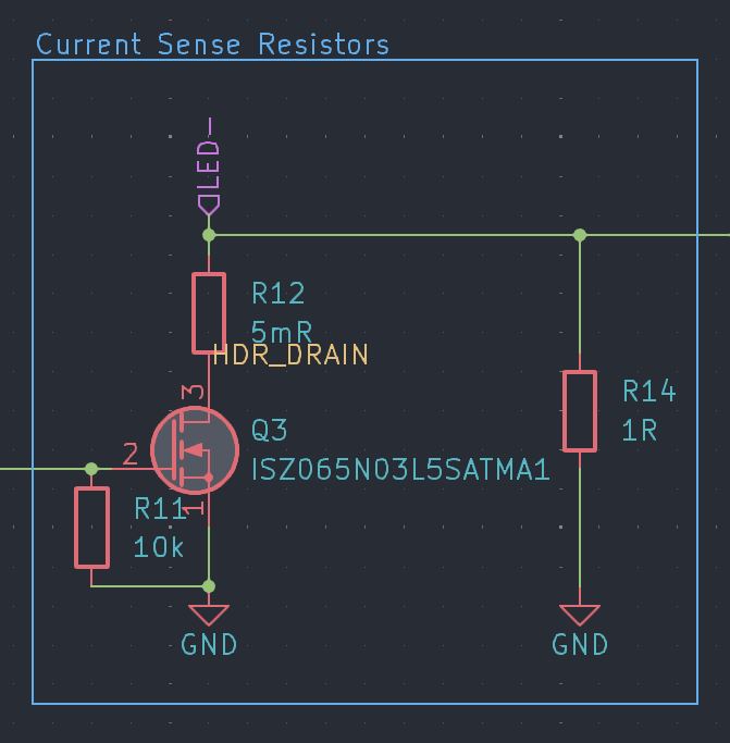
  • Even at same/comparable driver outputs values, switching HDR on eliminates the noise instantly, even without frequency compensation (driver output waveforms confirm this)
    • HDR off: 1 Ohm current sense resistor
    • HDR on: Current sense resistance is ~10 to 20 milliohms
  • The amount of noise changes with frequency compensation capacitor:
    • No capacitor: Loudest noise, and driver output waveform has clearly visible oscillations
    • 1nF capacitor: Noise is reduced, waveform amplitude decreases substantially
    • 22nF capacitor: Noise is reduced further, output oscillations barely visible
    • 100nF capacitor: Boost driver outputs seems to become unstable
  • The amount of noise changes with MP3432’s operating mode:
    • Forced continuous conduction mode (FCCM): No audible noise with frequency compensation
    • Pulse-skip mode (PSM): Noise is audible
    • Ultrasonic mode (USM): Noise is louder than in PSM
  • The inductor’s a Coilcraft XAL7070-222MEC, unknown if it’s coil whine

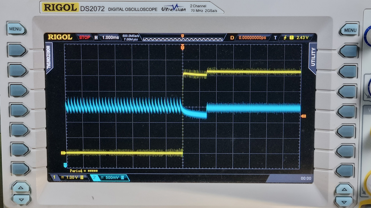
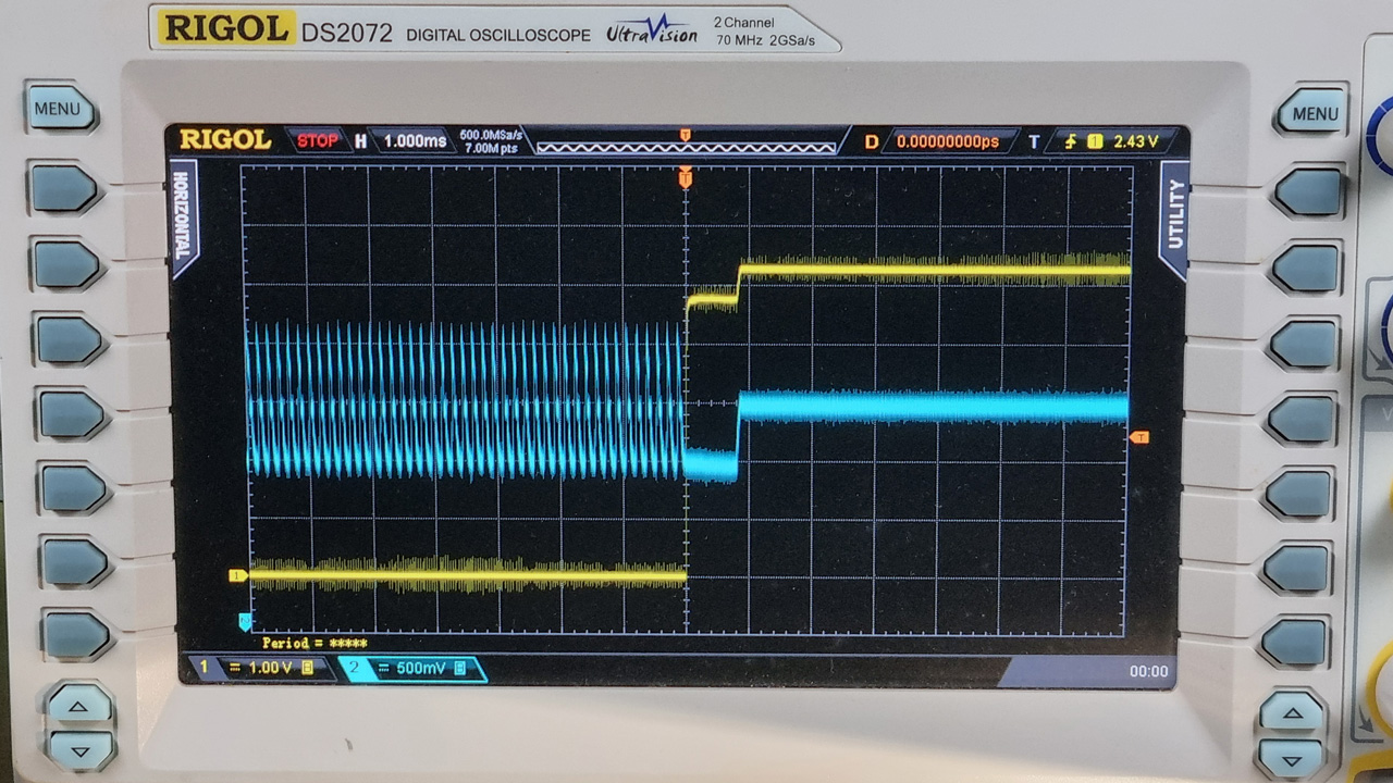
I’m currently fresh out of ideas, and will really appreciate any feedback. Perhaps the key is how HDR immediately stops the noise, even if the output voltage remains basically the same. So here’re some scope captures. Channel 1 (yellow) is HDR state (MOSFET gate voltage). Channel 2 (blue) is the driver’s output voltage.


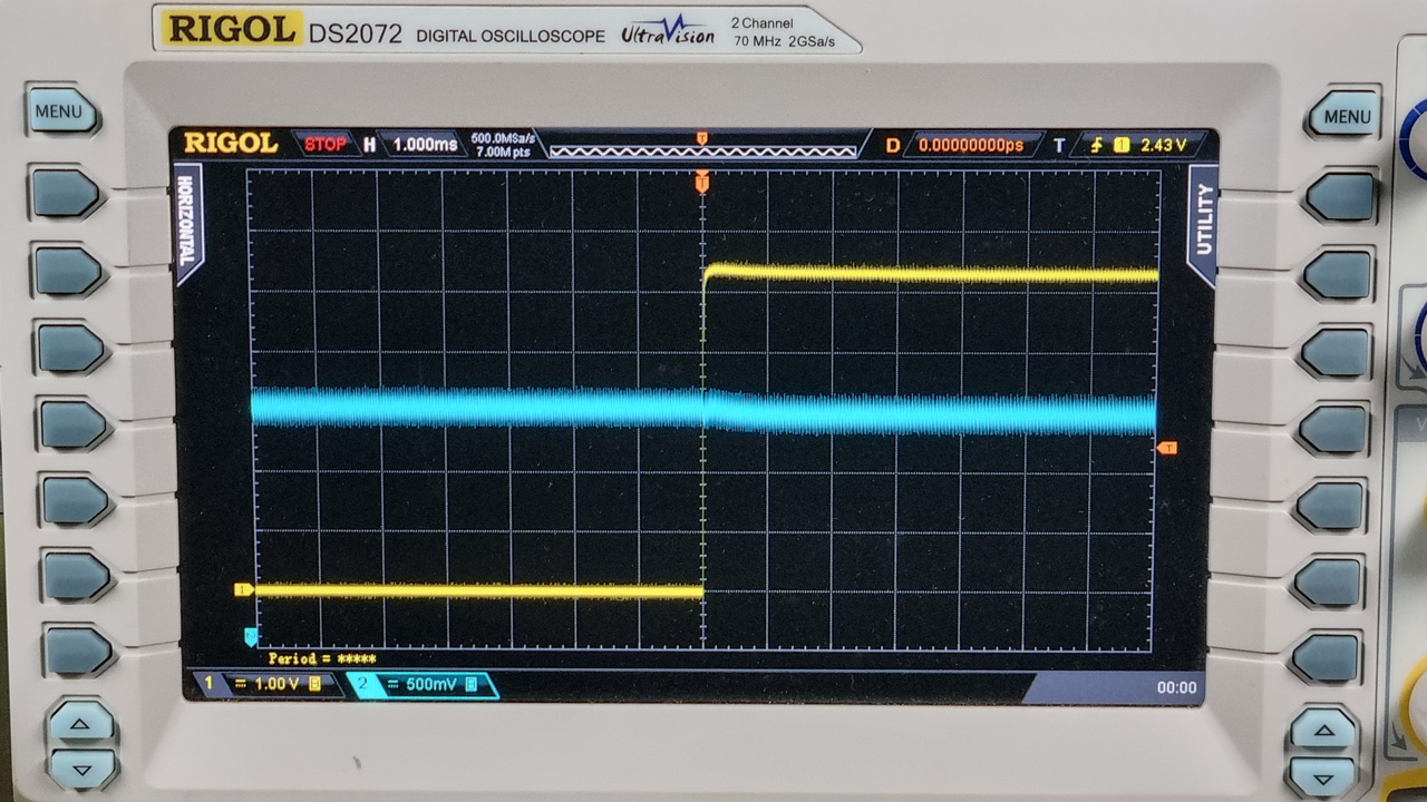
Frequency compensation: 22nF, Mode: PSM. Noise is barely audible


Frequency compensation: 22nF, Mode: USM. Noise is slightly louder than PSM


Frequency compensation: None, Mode: PSM. Noise is very audible


Frequency compensation: None, Mode: USM. Noise is very audible

Frankly, the noise might not be a major problem, but it’ll be amazing to figure out a real technical solution to this.

Thank you for reading!

4 Thanks

@engineerbo Welcome to BLF!

It’s a pleasure to have you onboard, engineerbo!

Thank you for the welcome! Still hoping someone’ll be able to help!

Maybe make a post on reddit r/flashlight and link this post, there could be someone over there that can help if no one chips in here. I find reddit a lot more active these days.

1 Thank

Will do, wanted to give this thread a chance before reposting on Reddit. Thank you!

AFAIK the whine is usually caused by vibration of the inductor coils. Maybe try to pot them with a suitable epoxy/silicon compound.

1 Thank

It might help to identify the source if you try pushing various parts of the driver with a chopstick or something and see if the tone changes/stops. I’ve used this to track down hum in other electronic projects, I’ve not tried it in a flashlight.

2 Thanks

That might be a good idea to find the source of the noise. I think it’s almost definitely the inductor, but my guess is it wouldn’t make an audible noise if everything is configured perfectly e.g. with ultrasonic mode, it should be switching at above audible frequencies.

The other suspicious bit is the noise going away when HDR is switched on, even when the voltage/current output is roughly the same.

I physically poked around it a today and couldn’t get the sound to change.

So I tried recording the sound with my (reasonably sensitive) USB microphone, and couldn’t record anything besides the quiet noises from outside the building. Interestingly I could hear it through the built-in monitoring output, so maybe I just have to turn the gain up even more.

What’s making the noise? Inductor or ceramic caps?

Honestly, I can’t tell at all. I used the eraser on a pencil to push down on the different components (input capacitors, output capacitors, inductor), and there was no discernable change to the sound.

Cool dev board!

Do you mind posting a schematic or clarifying what MOSFET gate voltage you’re referring to?

When you don’t use a compensation compensation capacitor at high output current, the boost converter’s feedback loop becomes unstable and hence the oscillations at the output. At lower output, the loop is more stable and thus no oscillations or noise. The noise is probably coming from the inductor, which is directly connected to the output. The output oscillations have a 5-6kHz frequency, is that what you’re hearing too?

Also, it’s not too clear from the board photo, but the compensation capacitor and resistor are recommended to have a separate ground than the power ground. Can you post a top layer layout from the CAD tool? Separating the two grounds may increase stability.


The gate voltage in the oscilloscope captures is for Q3, which is the MOSFET switching the HDR current sense resistor. The reason I included that is to show that turning on HDR (using the lower current sense resistance) stops the oscillations instantly, even for a similar output voltage and current.


The frequency compensation capacitor (C5) isn’t connected directly to GND. But the op-amp isn’t on a split ground either. I don’t think I did a fantastic job with the layout this time, but the return paths probably aren’t bad enough to cause problems with the op-amp. Also, if this were the problem, I wonder what the explanation is for HDR reducing the noise?

Molded inductors don’t usually make noise at low current, in my experience the noise nearly always come from the MLCCs in these cases, they have piezoelectric behaviour so they deform when a voltage is applied which makes the whole board vibrate, if the frequency is in the audible range (pulse skip or pulse frequency modulation) it makes noise.

Unfortunately MLCC with their low ESR are pretty much necessary in compact DC-DC converters.
You can treat the symptoms, for example by using dampened MLCCs, on interposers like Murata ZRA and ZRB product lines, or metal frame MLCC like Murata KRM.
Those are limited to 0603 and 0805 through, 0805 KRM 22uF 25V should be suitable for this but they are quite costly.
Supposedly placing placing MLCCs of both side of the board opposed to each others cancels out the vibrations, I haven’t tried it though.

Fortunately the MP3431/3432 with its ultrasonic mode doesn’t go below 23kHz at low output, so there should be no audible noise, except if there is some kind of oscillations/ringing in the audible range, which is what is happening here. Somehow, when the sense resistor value is increased, the regulation becomes unstable, the higher the value the higher the amplitude.
Out of the ~20 or so DC-DC ICs I’ve used in drivers with kind of CC topology (op-amp as error amp and dual Rsense), the MP3431/MP3432 is the only one with which this happens.
Even more weird is that the oscillations completely disappear when Vin is ~below 3.4V, this is the voltage under which the internal LDO powered by Vout instead of by Vin, but this doesn’t really make sense.

I’ve asked about this to a few EEs, but even people better versed in analog electronics didn’t really know why this was happening.

So far the only simple way I have found to solve this is to increase the value of the compensation capacitor in relation to the DAC-IN- resistor. Which is what you also observed, except if you need such a high value it’s that you probably used low values for the DAC voltage divider.

I guess another solution would be to power the Vin pin by a voltage under 3.4V, but this would require a LDO and more space used on the board.

3 Thanks

Thank you for the detailed response!

I immediately went and tested it with a lower input voltage. I set my bench power supply to 3V, but the noise is still audible :neutral_face:.

Regarding the potential divider on the DAC, here’s the schematic:

The circuit uses a 2.5V LDO for the ATtiny1616, and the “primary” current sense resistance is ~10mR (including MOSFET Rds,on), so the potential divider is calculated from that.

Side question, but reading your response, do you mean flashlight drivers don’t normally have an LDO for the MCU? I suppose since the ATtiny1616 is able to operate on 5V which is greater than a lithium cell’s voltage, it doesn’t really need an LDO. Are there any complications with powering the MCU with the battery directly?

hmm, maybe I remember wrong and I’m confusing with something else, I’ll recheck when I find the time.

I use 3.3K as bottom resistor and whatever needed as top one for the desired setpoint, with 1R sense resistor, 3.3nF comp is stable.

No they usually do, because they need a regulated VCC for the PWM signal (filtered), but if you use the DAC then you don’t. Usually I put a LPF before the MCU to be sure to have a stable VCC, but the times I didn’t it seemed to work fine too.

OK, I’ll recalculate with a 3k3 bottom resistor and give this a try. Theoretically it looks like the only difference would be reduced load on the DAC output, but at this point almost anything’s worth a shot :joy:

I just replaced the bottom resistor with 3k3 and top resistor with 150k. Tried it with 22nF frequency compensation capacitor, noise is still audible. So I switched out to 3.3nF frequency compensation capacitor, and the noise is still there.

Just to be ultra sure, this is referring to the frequency compensation capacitor on between the op-amp output and inverting input? And not the MP3432’s compensation pin?

New side question: at the lowest brightness, when I switch the power off, I’m seeing a tiny bright flash from the LED. I’m assuming the MCU browns out and things are running in the danger zone for a short period before all the input and output capacitors are discharged. How is this usually fixed if an e-switch isn’t used?

I know solution. Use some different converter :laughing: