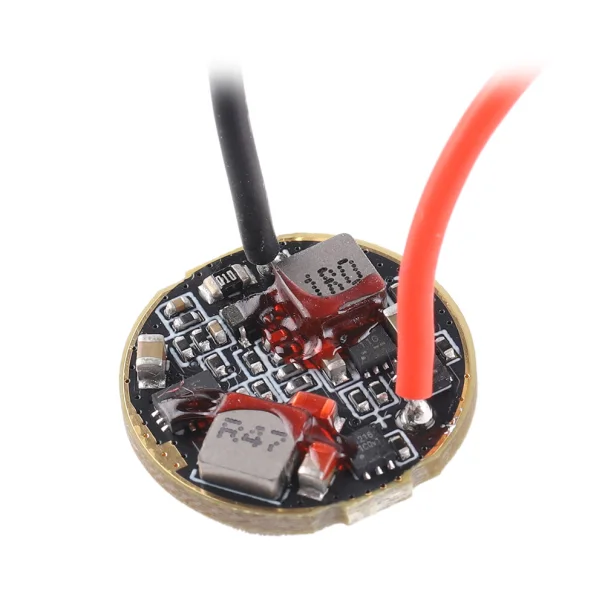
I am hoping to use a 12-group T3 NiMH driver for white LEDs to drive either a UV emitter (with higher Vf) or a SST20-DR (lower Vf). Is there a way to modify the driver to alter the output voltage?
For context: it has been documented that the output current can be tweaked by changing a sense resistor; there are reports of success in lowering the current of a buck driver, but not raising the current: the inductor overheats and results in catastrophic failure. I wonder whether an analogous modification exists for changing output voltage instead.
I am not really sure what you want to achieve. The idea behind a buck/boost driver is that it should adjust the voltage itself according to the set output level as long as the LED forward voltage is within the specs that the IC can handle. LEDs have negative temperature coefficient so voltage adjusting is what the driver does all the time.
Convoy dual fuel drivers are of cascaded boost+buck type (or look like it at least, they also could be boost-or-buck, but they are not buck-boost), so CV boost followed by CC buck. (the 5A one looks to have a boost bypass FET for li-ion)
Boost voltage is set above white LED Vf, but if an UV LED is used, the boost voltage might not be set high enough, which is reasonable enough, we don’t want to boost too high if not necessary since that would waste some power.
Secondly Convoy has the annoying tendency to set a very small output voltage range for their drivers, so small that I have tested drivers that actually cannot achieve full output with their designated LEDs (for example 22mm 3A xhp50.3 driver, which only reaches something like 2A with said LED ). Other times it means that a 12V FC40 driver can’t drive an XHP35 to full output again because the range doesn’t go high enough for the XHP35 higher Vf.
It’s stupid of course, and not something you’d do in your drivers so I understand why this limitation didn’t occur to you (it took me some timewhen I tested that fc40 driver to understand why it couldn’t drive that xhp35 fully).
@QReciprocity42
Anyway, modifying the CV boost voltage requires probing it to determine if changing it is needed, then identifying the boost FB voltage divider and swapping one of the resistor to adjust the boost voltage (5A driver look to be using TPS61021A).
Modifying the output voltage working range requires identifying the buck (likely an MP2145 clone) FB divider and the OpAmp output resistor, then either shifting the range up or down by changing the value of one of the FB resistor or widening the range by decreasing the value of the OpAmp OUT resistor. See this falstad sim to help with this (MP2145 FB voltage is 0.6V, not 1V, and of course resistors values would be the onboard ones).
But, well, this is a bit advanced, and the resistors being 0402 on this don’t help.
Wow, thank you so much for the incredibly informative explanation!! I did not realize that the driver is boosting a AA cell then bucking it, not just a pure boost.
Without modification, this is exactly what I’m concerned about. I’ve got an S21E with 6V 3A boost and SFT70, and also noticed that it does not seem to output as power as specified.
Concerning the T3 driver I asked about: I haven’t tried to put a UV LED in it yet. But I’ve tried putting in a SST20-DR: all lower modes become indistinguishable, and the driver gets super hot super fast. So the output voltage range does not seem to have enough tolerance to drive emitters with slightly different Vf.
Thank you so much for thinking of this process and sharing the relevant resources! I need to pull up some driver photos and read this very closely. Fortunately, I recently soldered some 0402 resistors while messing with the T3 driver (trying to fix the annoying moonlight flicker on NiMH), so that is not a problem.
I see, my initial question might be better phrased, then, as:
What components are responsible for determining the range of output voltage the driver can handle? Is it the IC or more elementary components like resistors? Additionally: the driver is known to not handle the lower Vf of the SST20-DR. How could I modify the driver to work with it?
That’s probably better answered by thefreeman. Without knowing the schematics of the driver it’s hard for me to say. If there is a resistor divider between LED out and GND, then changing one of those resistors would change the voltage to the feedback pin.
Judging by the general layout of the components of the 5A dual fuel driver, especially the two mosfets either side of the +LED wire (which I believe to be these https://rt.rectron.com.tw/uploads/mosfet/rm1216.pdf), this driver seems to work either as a buck with liion or boost with NiMH/primaries. So the MCU probably measures the voltage of the cell after switching the light on and then enables the corresponding dcdc ic and mosfet depending on whether the driver needs to buck or boost. Could be wrong tho, this just makes the most sense to me. But having said that, I do wonder how the opamp can control both the buck and the boost converter without their respective feedback dividers influencing each other.
Changing the output voltage range can be done by changing the feedback network of I guess both converter ICs or by decreasing the resistor on the output of the opamp, as thefreeman already mentioned, so it has more “control” over the feedback.
This resistor can be critical for the stability of the current control loop tho, as I found out by simulating my own buck driver. If it’s too low in value, current can start to oscillate. So that’s one thing to keep in mind when decreasing this resistor.
But without schematics of the driver, finding the right resistors might get quite difficult.
Yes you’re right the layout does seem to indicate boost-or-buck instead of cascaded boost+buck (convoy does have other boost+buck drivers though). And I also wonder about how the opamp circuit looks to control both converters.
Thank you so much for the analysis! Looks like I shouldn’t mess with it with my current lack of expertise in electronics. It already seems to have stability issues, with a irregularly flickering moonlight on NiMH.
I’ve got a retired driver on hand, so here are photos of front and back. It’s pretty messed up from my attempts to fix the flicker, and one capacitor has gone missing, so I’m also attaching some high-res photos from the website. Missing part circled in green.
Let me know if you want to zoom in on specific locations, my phone doesn’t focus equally well across the whole driver.
I might get myself one of those drivers and try to reverse engineer it. I have one in a T2 but I’m scared of slipping and ripping off some components while unscrewing the retaining ring.
Could this small output voltage range also be the reason why the “moonlight” mode and 1% mode of the S21e 3A boost driver basically look the same? As in the driver can’t lower its voltage enough to reach the desired current?
Also, could I figure out the maximum output voltage of a driver by running it without an LED connected? In this configuration the driver should output its maximum voltage as it tries to let a current flow. By measuring this voltage one can get an idea if the driver would be able to fully drive a certain LED with its stated current.
 ). Other times it means that a 12V FC40 driver can’t drive an XHP35 to full output again because the range doesn’t go high enough for the XHP35 higher Vf.