Thanks for the explanation, that sounds doable for me. I can do basic soldering so I will give it a shot.
—— Edit
On second thoughts maybe I will try to flash the firmware as you suggest. I will have to do some research first.
Thanks for the explanation, that sounds doable for me. I can do basic soldering so I will give it a shot.
—— Edit
On second thoughts maybe I will try to flash the firmware as you suggest. I will have to do some research first.
The current driver is probably soldered to the pill since the 7135’s usually prevent the use of a retaining ring. In my experience removing the driver and then re-soldering it is the most work. This will be the same either replacing or flashing it. The 4x7135 driver only has the 7135’s on one side but unless you have the retaining ring you will have to solder it to the pill.
Mmm, if lowering the output is the main issue, removing the two back soldered 7135s would probably be the easiest option.
Reprogramming the firmware, as MILSPEC says, would be intended to find an adequate lower output mode. However, since in these drivers lower modes work via PWM, I'd prefer to go the 4 chips route for fully regulated operation down to the gradual effective cutoff point, which would be below 3.5V for 4 × 7135s. With PWM, gradual cutoff point raises as duty cycle gets lower. ![]()
Cheers ^:)
Programming USB adapter and the clip costs less than 4$
All you need is a PC AVR exe and the hex file
Thanks for the comments everyone. It gives me a better idea of the steps needed and potential pitfalls.
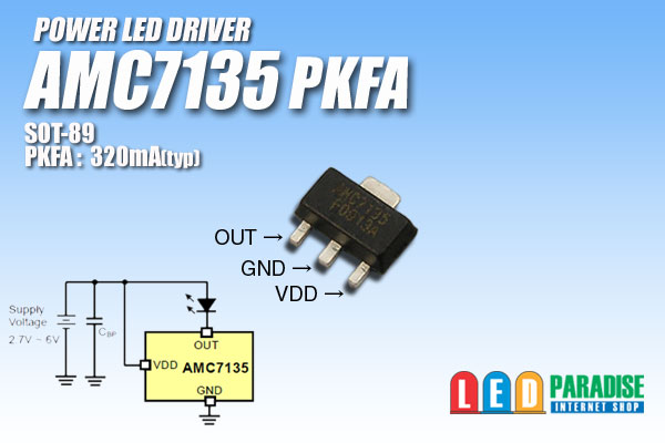
Major components of a flashlight are the light emitting diode (LED), one or more batteries, and the driver. That is a circuit board that regulates the amount of power fed into the LED. The current is regulated by AMC7135 LDO’s (Low Dropout Current regulators). Each unit is capable of handling 0.35A of 0.38A (depends on type). Want more power? Just put more AMC’s on your circuit board. Commercial boards have 2 to 12 AMC’s. Convoy used to put Nanjg 105D drivers in the Convoy S2. Recently they install a driver of their own design. The basic layout is the same however. Drivers in an S2 can have up to 4 AMC’s on the side of the circuit board facing the LED, extra AMC’s will be placed on the battery side.
AMC’s on the battery side of the board prevent the use of a retainer ring, so the driver will be soldered to the pill.
For some insight into the anatomy of the circuit board, follow this link
.
Want less power? Remove one or more AMC’s, or go quick-and-dirty by clipping the “out”-pin of one or more AMC’s.
Or you can do it the elegant way: by reflashing the MCU. In that case you have to remove the driver from the pill. Because the MCU is also placed on the side of circuit board facing the LED (inside the pill). This can be done by desoldering the board. Or like I did it myself: by using a pen-knife (watch your fingers).
After the reflashing you can solder the board back into the pill, or use a retainer ring (clean out the threads in the pill).
These rings can be bought at Fasttech 
Good luck!
I would cut the VDD pin, so that the little fellow is turned off (in stead of trying to push its 350 mA into nowhere).
This is electric energy! Look at the light switches at home: are they turning red because they have to stop the current?
Or do you pull out the cable “before” the switch in order to relieve the switch?
I would prefer to turn a 7135 off in stead of cutting its output.
I’ve always wondered why people just don’t use micro shears to snip a leg or two of of 7135’s instead of breaking out the soldering iron …seems way easier.
So lets say I decide to remove the two visible 7135s (I am still weighing my options) - I just have to put a fine tip iron onto the legs and pull that sucker off?
It’s better to heat the big tab on the other side.
This is the same piece of metal as the centre leg, and it will heat up the whole 7135 so the solder on the outer legs will melt too, and then you can move the whole thing.
Preferably take them off with tweezers.
The PCB traces may get damaged when you do that.
Okay, thanks. This is probably what I will do.
I will gift this S2+ to my father when I get the output down a little. Then I will probably order another S2+ from Simon with the options that I prefer.
When I ordered this one 3 months ago I didn’t really have any idea what my preferences were in terms of tint, power, modes etc. It was quite overwhelming.
Now I think I have a pretty good idea ![]()
So I tried to remove 2 of the 7135s. It did not go as smoothly as I hoped, I had trouble loosening the solder on the legs and when I pulled the chip it just came apart and left a metal base (?) which I could not remove no matter how much I tried.
Anyway the torch still works so I think I accomplished what I set out to do. Is there any risk (of shorting etc) by leaving these metal pads/base exposed like this?


Also thanks for the comments and suggestions above.
You can always use a heat gun to melt the whole side of a PCB and remove single oarts with tweeters
This is how I reflow drivers
To remove a single part from a bigger PCB I use a tiny gas torch carefully
That’s likely because most of the heat is going to the pill. Soldering on assembled lights is always tricky.
soldering under this conditions need a good iron with thick clean tip and fresh solder or heat gun to warm up the pill as well
On second attempt I got those remnants of the 7135s off. So it’s all good now.
I find that it’s easier to remove them by sliding them sideways after bridging all 3 pins with solder so all the pads melt at the same time. Surface tension holds them down otherwise.