Thank you for the detailed explanation!
Hi all, here is a pic of the driver I got inside the l21b SFT40, it’s supposed to give 8A.

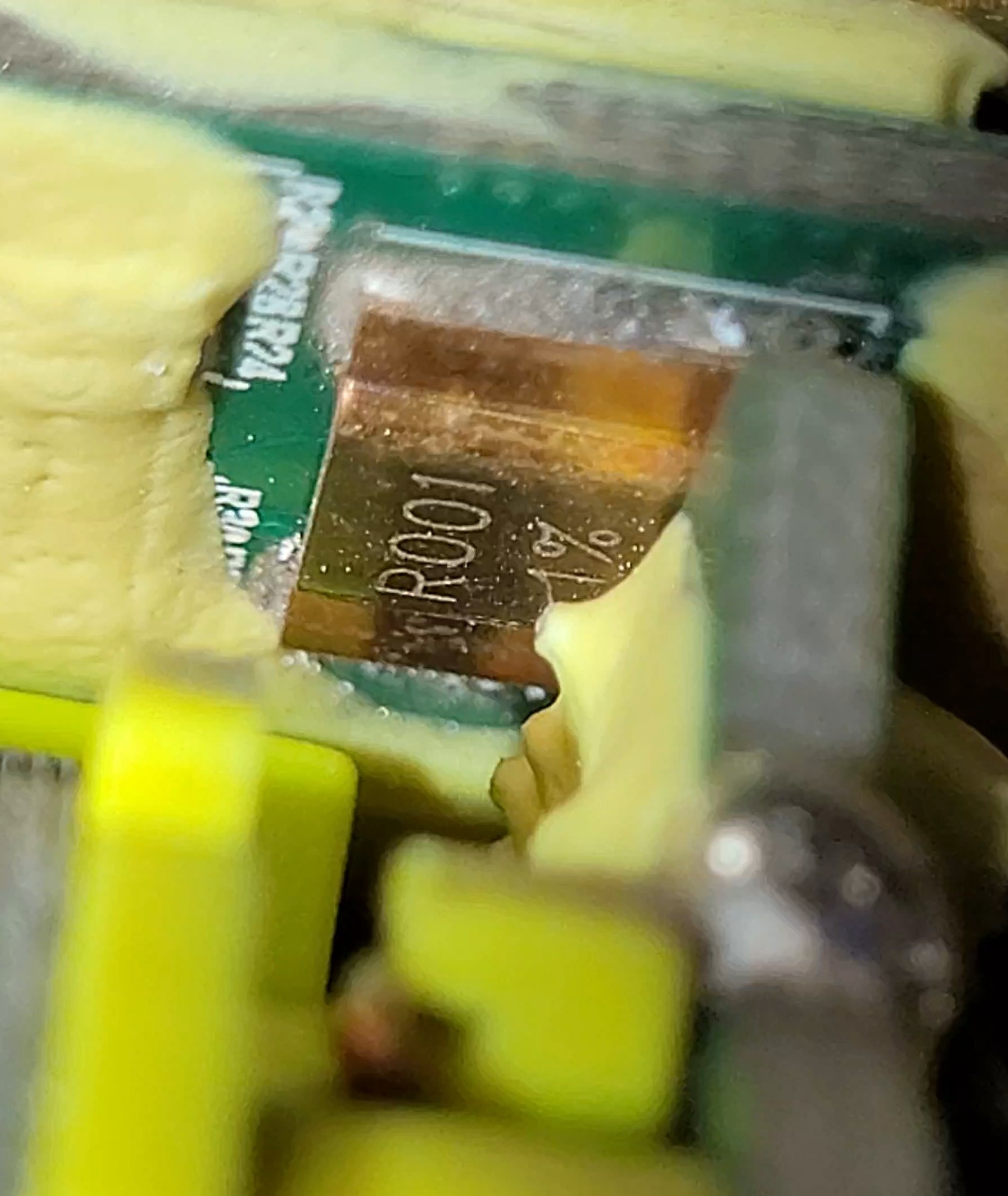
The biggest resistor seems small, much smaller than the big 2010 pictured in the new “5a” drivers. I’m not sure I’m up to changing it and there was no room to measure it. I’ll measure if I swap LEDs.
I bypassed the tailcap with a 13cm 8ga wire and measured 7.5A at 100% and 3.26A at 50% (group 8). I wanted to use group 8 and swap in a w1 led (green probably) but 3.26 seems underpowered.
Would you be able to make out the part number on the regulator ? it’s the chip south east of the inductor (biggest part).
The sense resistor looks to be 1206, it’s appropriate.
The driver you are using is a switching driver. This means it only takes from the input whatever power it needs to produce its output power, plus the usual additional power which goes into conversion heat inefficiencies which should be quite small in that driver.
Your measurements are thus, well, probably correct; your conclusions, though, are not. The driver is more than likely outputting ≈8A to the emitter in high, and the same I would say (≈4A) for the 50% mode. The reason it pulls even less current in proportion for the 50% mode is because it needs less input power (which is voltage times current) to produce “about half” of the output power (vs high), because of lesser input voltage losses at the driver (less current through the switch, springs and etc. means less voltage drop) and less power conversion efficiency losses (higher driver efficiency).
For switching drivers you need to measure “the real thing”, which is the current at the emitter. This can be done, for example, installing the driver in the pill or body of the flashlight, and then connecting it with extension wires to an external emitter in a heatsink. Then use a clamp meter to measure the flow of current through one of the wires from the driver to the emitter.
P.S: for measurement purposes the external emitter in a heatsink can be whatever type, but better if you don't choose emitters with very high Vf; if you do, buck drivers may not be able to output enough voltage for it (unless you feed them with high enough input voltage, that is).
Thanks for the insights! I was curious about the large coil, I thought it might be a switching driver… I guess we have to speak in terms of power and not stricly current. I will measure again sometime this week with a p42 molicel for which I have the datasheet. Also, aren’t some switching drivers actually more efficient closer to the higher power limits?
So would you approve a simple LED mcpcb swap to properly drive a cslmn1 (w1)? 4A is about right for w1… Does the Vf matter for spms? SFT40 seems to have lower Vf at 4A than W1 (FY and F1) (although djozz test of w1 F1 green seems weird it may had to do with a missed/bad solder job)
By the way, I am curious about how this driver is adjusted, is the voltage factory adjusted to match the higher Vf values of the LED, then current is controlled by the UI? ( I’m just picturing how this aliexpress spms I use is voltage and current adjustable through two small trimpots … I’m not super knowledgeable about how they interact with a load such as diode that forces a voltage drop (Vf) ).
I’ll also try to get a look at the markings on the big chips near the coil for you thefreeman
For the regulator JaredM helped me figure out the part here .
The driver is current regulated, the Vf of the LED doesn’t matter (as long as it’s a 1S LED).
As a rule, I would say no. Check this thread, it has some charts with efficiency and other data for a few boost drivers: Buck and Boost Drivers, Testing, Modding, and Discussion
The driver adjusts its output voltage by sensing the output current flow or current flow to the emitter. For this to happen the current goes through a sense resistor, usually a very low value power resistor located just before the negative output wire. Because current times resistance is voltage, this voltage drop at the sense resistor terminals is amplified and sent to the microcontroller. This is the way the microcontroller “senses” the output current and thus knows if the current flow is correct for any mode, and when not it either raises or lowers the output voltage. This is done at a very rapid pace, probably thousands of times per second although in this respect thefreeman can provide more accurate information.
Since buck drivers can only reduce the output voltage, not raise it, when the led requires an output voltage which is too close to the input voltage or even higher, the led won't receive the full current. This happens at some point as the battery is discharged and its voltage drops.
What do you mean with spms? Closest abbreviation to it I know is smps, for switch mode power supply… :D
I have a few of these buck modules. They are CC/CV DC-DC converters. You set them up by adjusting their potentiometers. Whatever voltage you set them at with their CV or constant voltage potentiometer will be the output voltage or maximum output voltage. When you don't need or don't want current regulation at all, you set the CC or constant current potentiometer all the way it goes (clockwise rotated, in my experience), this way you'll always see the full output voltage until the module protects itself because of some overcurrent or overheating problem. If you adjust the CC potentiometer and set some output current (connecting the leads from a multimeter in amperimeter mode is a way to see the output current, for example, at least if output voltage isn't too small), the module will reduce the output voltage if it senses that the output current is beyond the set value.
These modules are nice, I have a few at home, but because of the parts they use for current regulation (the onboard operational amplifier -LM358?- and linear voltage regulator, I guess) the will only work in CC or constant current mode if the input voltage is beyond a certain thresold, 6ish volts, close to 6.5V if I recall correctly. For this reason they cannot work in CC mode when fed with a 5V supply. This also happens in other similar DC-DC converters like the LM2577S-ADJ CC/CV SEPIC module (A.K.A. LM2577 CC/CV boost buck converter), and somewhat sucks.
P.S.: I would swap the current sense resistor in the Convoy 8A buck driver, with a 18mΩ (R018) for example the maximum output current would be 4.4̅4̅4̅A.
Wanted to say thanks @thefreeman, this comment was very useful in modding my 17mm 5A Convoy driver down to 3A.
I changed R2 from 510kΩ to 1MΩ. I now measure 3.1A (down from around 5.4A)
For reference:
R1 = 100kΩ
R2 = 510kΩ (stock)
R3 = 24kΩ
3 Thanks
Hadn’t seen this post before, I chose the 7135x8 12-group driver, also for the 219b.
Hi, can I ask what resistance value I need to change the R2 to (at least theoretically) if I want to change the driver to 4A? Or is there a formula for that? Thx.
the relationship should be Nominal current * default resistor = desired current * new resistor
→ nominal current/desired current * default resistor = new resistor
1 Thank
Thx, I’ll try it someday
Around 750kΩ for R2 should get you close to 4A. I don’t know if you can find one at that value in a standard kit of SMD resistors so pick something close.
1 Thank
Thx