Since Convoy’s drivers don’t have a proper moonlight, I decided to turn the lighted tailcap into a moonlight substitute, and add a battery indication function to it. The idea behind the latter is simple: if you wire LEDs with different color (thus Vf) in parallel, as battery declines, a greater proportion of the power is sent to the lower Vf color, which is perceivable by eye.
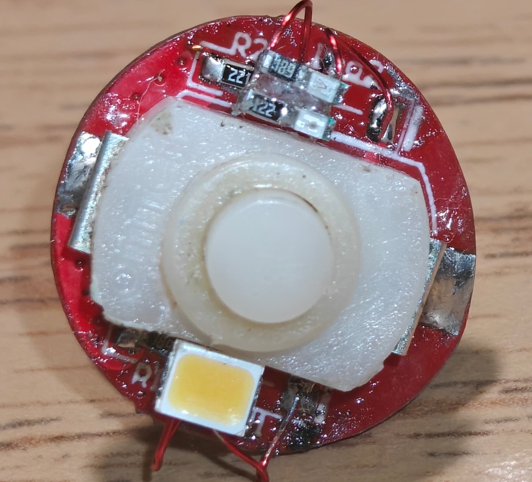
I used 2 types of resistors: 3 copies of 1200 Ohms and 1 copy of 680 Ohms. The switch PCB is populated by 1200’s, while the resistors in series with the color LEDs are 1200 for red and 680 for green.
White light is provided by a SunLike 4000K, which ends up around 3500K behind the silicone cover. I chose an 2835 LED because it directs more of the light forward than a typical SMD emitter, and thus puts out more light OTF at the same power.
Current draw of the whole system is under 1mA and not measurable by my multimeter.
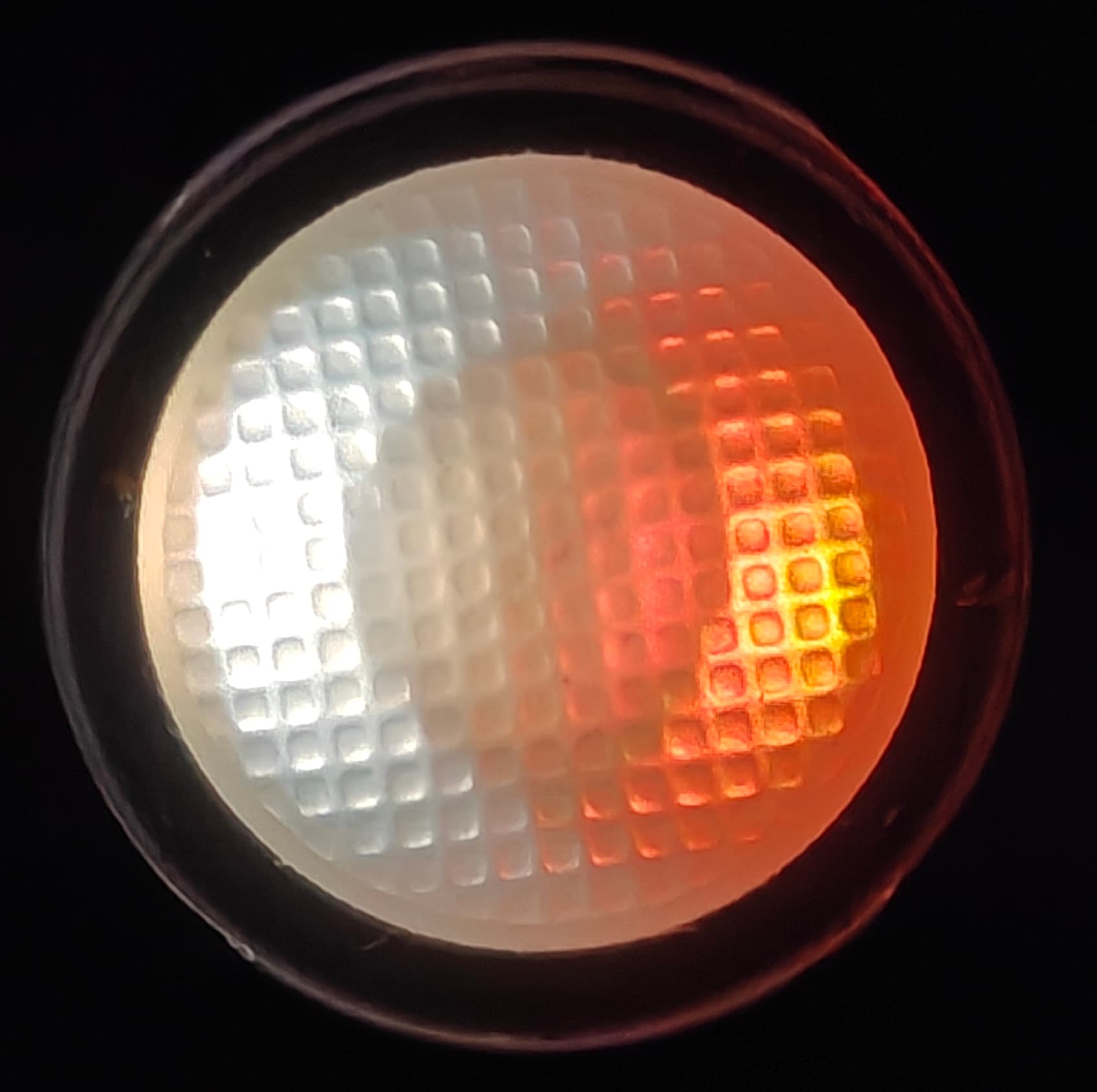
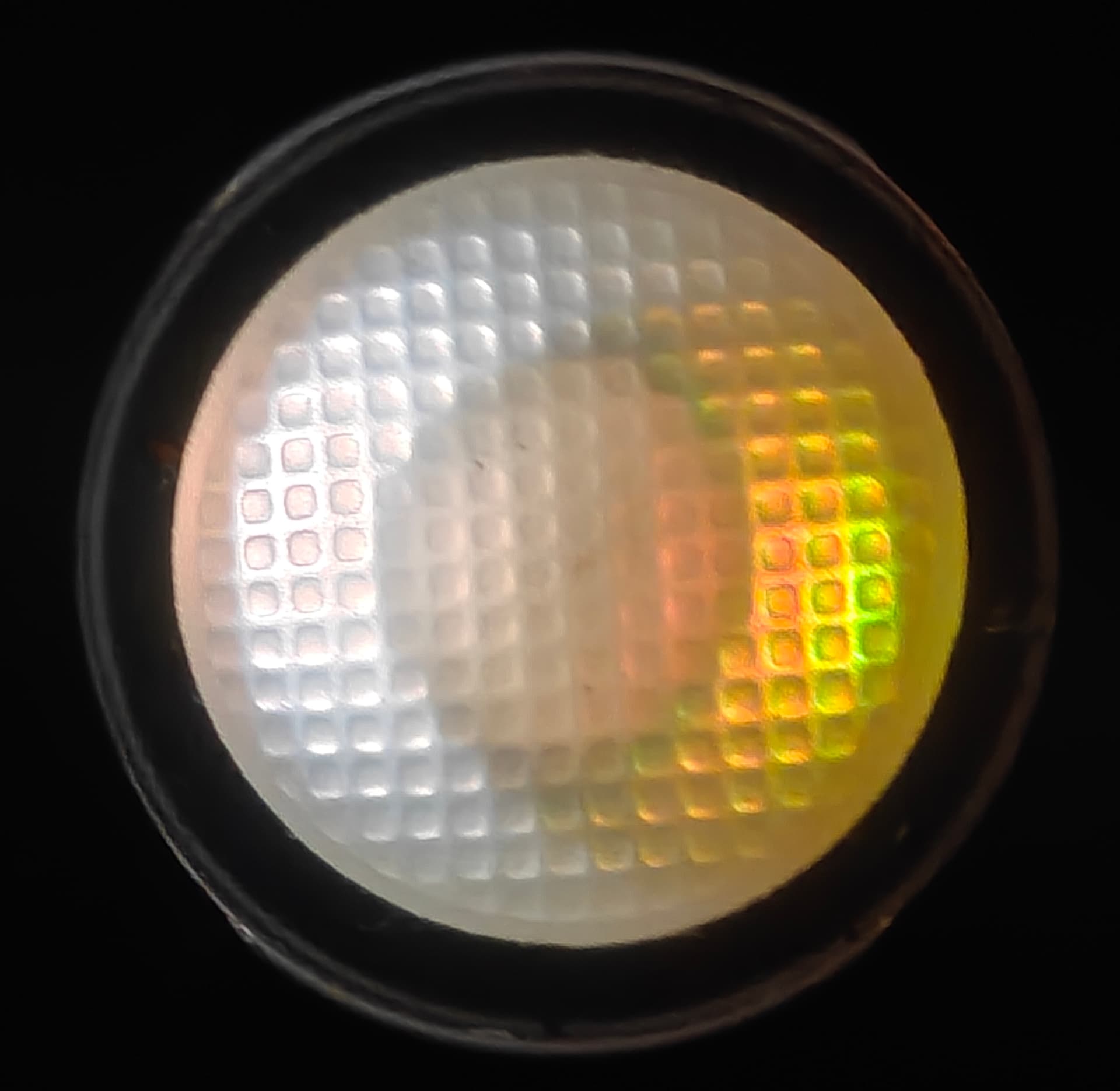
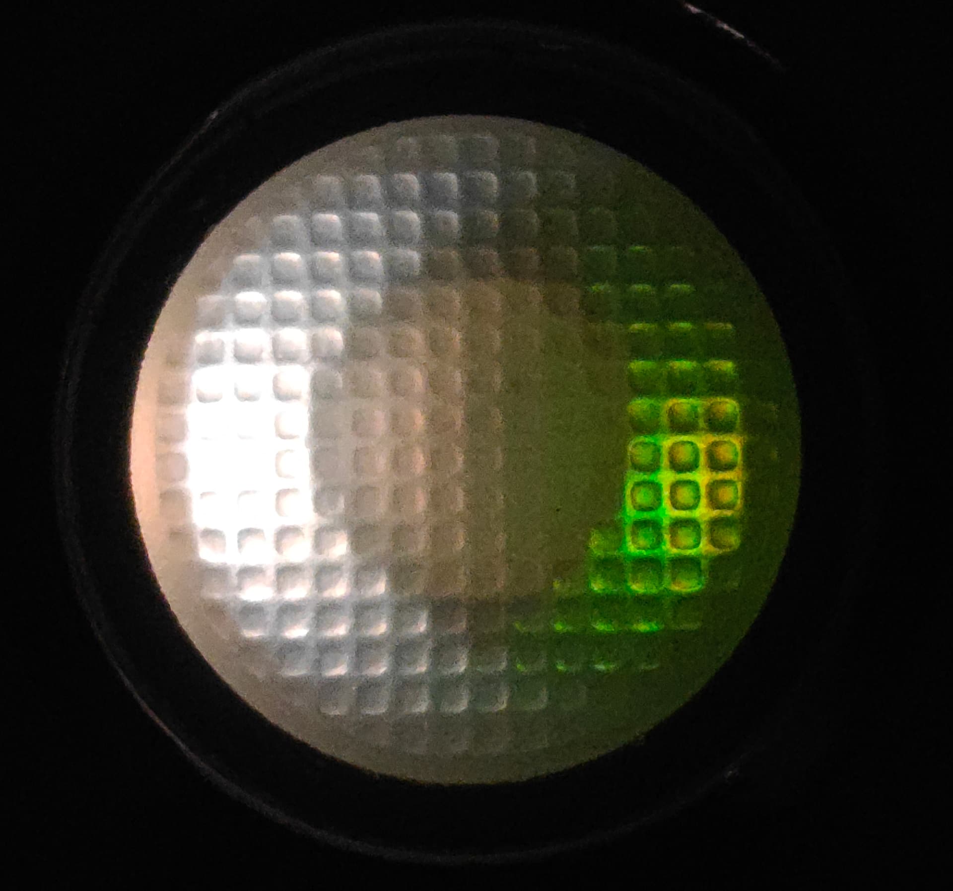
Tweaked the resistance values to better bring out the color contrast. Now 3.6V vs 4.2V (not quite the same comparison but the increased contrast is there):
1200 Ohms at 2 places: on the white emitter side of the PCB, and in series with the green emitter
3000 Ohms at 2 places: on the indicator side of the PCB, and in series with red.
Some tricks are needed to solder the small SMD components together without a PCB. Use a fine tip iron and put everything face-down on silicone “magic” tape, which is heat-resistant and holds the components in place.
The photos are not under the same exposure settings, though the brightness difference is close to what my eyes see since the phone’s camera doesn’t have the same dynamic range as the human eye.
This is great, I love that you’ve achieved it without any logic gates, transistors etc. I will definitely try it! Do you know any good sources for 3V 2835 emitters?
Thank you so much! As much as I wish I did, I have no knowledge about circuit design and thus must come up with a simple way to achieve voltage indication.
Alternatively, if you don’t care as much for CRI and just want cheap white light, any generic 5V LED strip on Ali comes with 3V 2835 LEDs.
The 2835 footprint is really unimportant; even 3030 or 5730 could do. It’s just that these types of LEDs are encased in a white material that reflects more light upwards than off to the side.
This looks amazing, great idea! This might be the best improvement to Convoy lights since the introduction of buck drivers.
Am I understanding it correctly that both the moonlight and the green and red LEDs are always on when the flashlight is turned off? If so, how long would it take for them to drain an 18350 battery with 1100 mAh?
EDIT: AI says “With an average current draw of roughly 0.8 mA, the 1100 mAh battery will last approximately 57 days (just under 2 months) before the white LED turns off.”
Thank you–I am honored by the comparison to the introduction of buck drivers!
Yes: the moonlight plus indicators will all be on when the light is off. It is difficult to estimate how long it would take to drain the cell, but there are heuristics to suggest that it could take a long time:
The current draw starts at less than 1mA, so assuming constant draw, it lasts a month and a half.
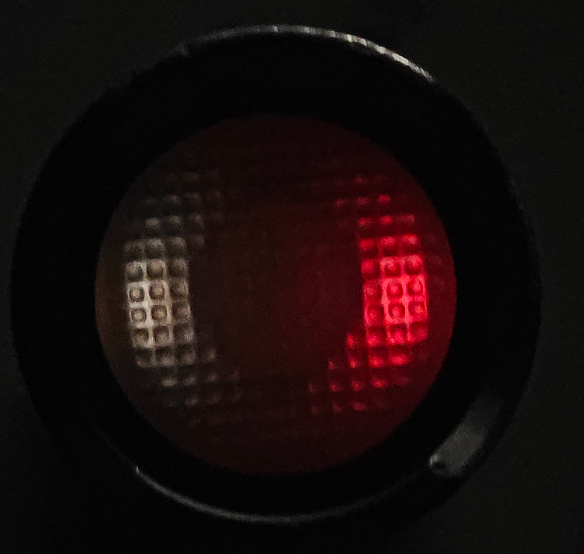
The issue with the above estimate is that the current draw is not constant, but declines quickly with lower battery levels. The 4.2V and 3.6V photos above are taken with different exposure values, else the 3.6V one would be invisible, on the order of 100x dimmer than 4.2V.
If one uses brightness as a proxy for current draw, there is good reason to expect the setup to last at least a year. Plus, if the brightness ever drops below, say, 3.6V, it would be immediately obvious.
Also, one can increase the resistor values to extend the runtime arbitrarily!
Maybe we could convince Simon to just use different colors+resistors for the 2 LEDs on his switch, which is an even easier way to achieve the same function.
This is very cool. I don’t need the white emitter but a simple low drain red green voltage indicator I’m down for. Will this cause less driver issues than the normal lighted switches? I assume so if the current is lower.
Good usage for the tail cap light!
If I were to do it, I’d choose a R70 LED with highest efficiency for the moonlight. For such low illumination, human eyes have trouble disconcerning colors so a high CRI LED with lower efficiency is not really needed.
For me, at such low illumination levels a brightness change of x2 or x1/2 isn’t super noticeable without a side-by-side comparison. The CRI difference would be visible though, especially if I use the light to read, say, a program during a concert.
Also it makes me happy to look at the tailcap (which is quite bright, enough to be visible outside during the day) and see the soft quality of the light that comes from being 98/99+ CRI. Nichia 519A doesn’t even touch these sunlikes, which have much better cyan, which in turn also improves the appearance of reds.
I was thinking about what you’ve done here. It works so well because the indicator LEDs are sharing the 3000 ohm resistor. When green is open it has less resistance than red and takes most of the current, when green shuts down due to VF red gets more current.
With Simon’s PCB they wouldn’t share resistance and the red would be at full brightness when battery is full. I don’t like that.
With that arrangement I think i’d prefer to see two white LED’s that just get dimmer as battery voltage drops like your sunlike did. But maybe one or both should go off completely at 10% to make absolutely clear that you’re nearly empty.
BTW, do the sunlike pads vaguely match the PCB? Wondering if it’s possible to reflow the sunlikes to it.
I don’t think that’s necessarily what’s going on–I’ve experimented with the setup more in the last couple of days, and even if you have just 2 LEDs with separate resistors, the color change still works. As long as you use a high enough resistor for red, the other color will have no trouble showing even at full battery.
I don’t think so–the latest PCBs use 0603 rather than 1206 LEDs, which gives you less room. Plus, using the wires is both easier and more transmission-efficient than reflowing to the PCB, so that remains my recommendation.
Is the red much dimmer than the green?
I’m guessing this is one of those things you have to see in person to really appreciate the effect.
I perhaps wrongly interpreted the second picture as the red being pretty bright at 3.6v.
At a full battery, yes. What makes things additionally tricky is that green is a much brighter color than red even at the same output, which needs to be considered during the design. I just gave up on calculations and tried resistors until I found a combination that worked.
Ah I see, the 3.6V photo has a much higher exposure to bring out the colors. If the two photos were taken at the same settings, the 3.6V would be too dim to make things out.