The old firmware held 100% until 50°C before a slow decline over 8 minutes, with no further reduction. Your graph started that decline early because you used a high capacity, low current, 21700, the voltage sag triggered that stepdown.
The new firmware, on the 22mm, steps down immediately to roughly 80% regardless of the cell used.
This behaviour was put in place to stop this component from burning out at full power, in the old problematic batch. Makes me wonder if this same component has been used again.
Yes, I wish there wasn’t so many changes without being informed. I don’t think Simon is even aware of the changes to be fair, it’s the driver manufacturer making these decisions. Another reason Simon should change suppliers so we can use custom firmware, it would solve so many problems.
Bummer. For the record, I used a 30T for the current testing to eliminate issues related to sag and to see the current potential (under 9 amps). I used a Samsung 50G for the runtime. It should have been good for 10 amps.
I was thinking of upgrading some of my custom lights with the 10 and 8 amp boost and buck driver (17 mm and 22 mm). Am I better off getting the 17 mm?
Are there lther sources for buck and boost drivers that may provide a bit more certainty? Especially in terms of temperature control and maybe efficiency?
I dont have the ability or inclination to learn to write firmware.
My new SFT25R has arrived, and it does appear to have greater output than the old version. At 3.7V I measured +20% output compared to the old, though I’m still unsure whether to attribute this to higher efficacy or lower Vf.
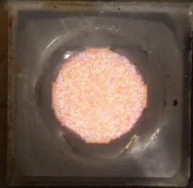
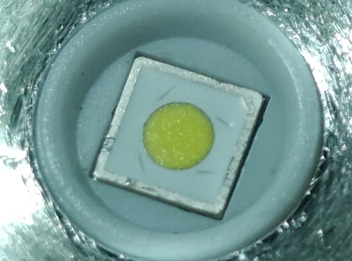
The production process has definitely changed. The new emitter’s die shape is no longer a smooth circle, but appears to be some jagged rectilinear approximation to a circle, similar to the below photo (source).
The issue of uneven phosphor deposition seems slightly less bad than before, and on very low currents the emitter seems a bit greener than before. Doesn’t bother me though, and the tint cleans up nicely above medium.
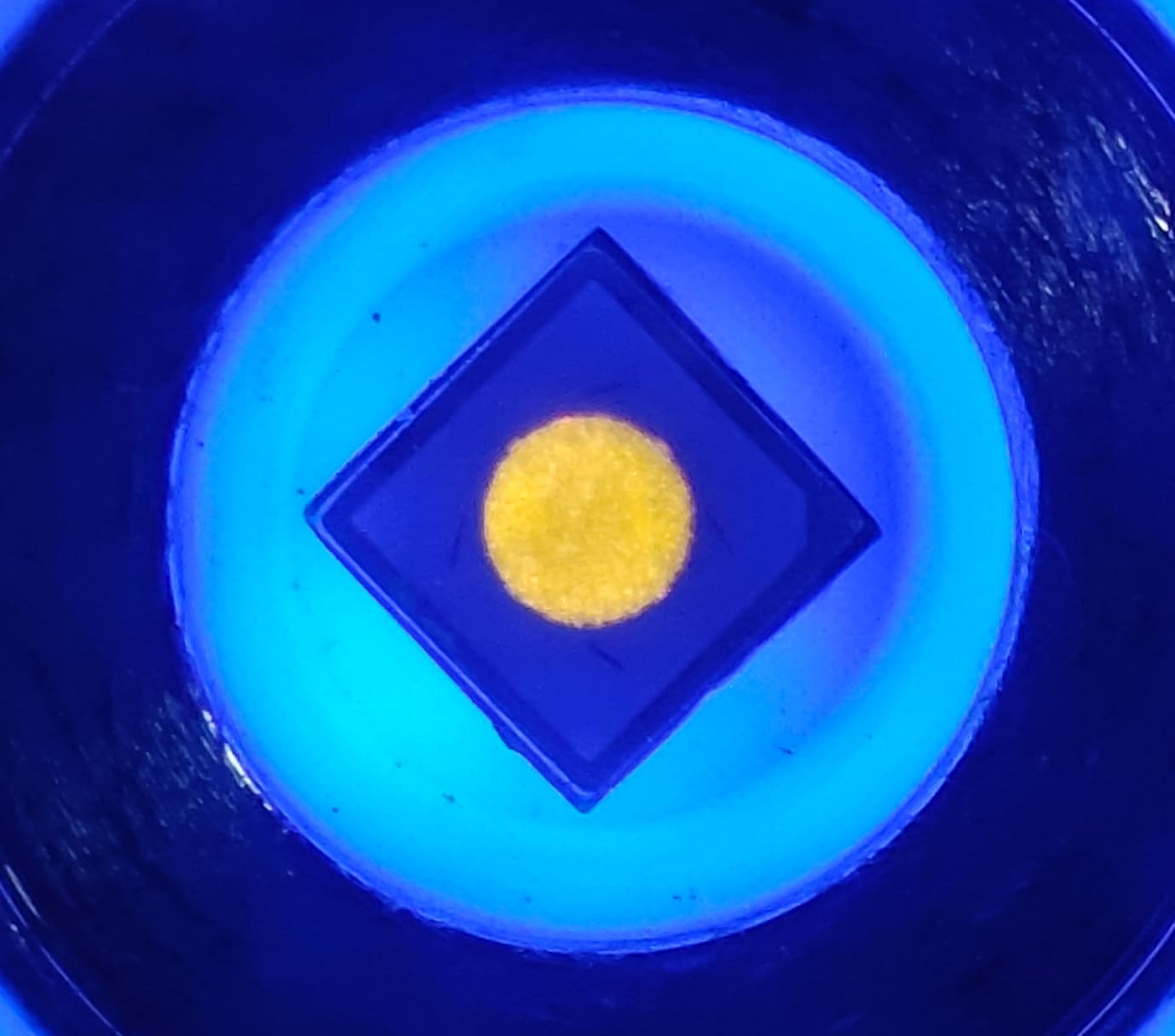
Not a good photo. I just tried to take one under UV to highlight the LES, and the rectilinear jaggedness is slightly visible as 4 bumps along the circle pointing toward the edges of the square footprint.
My sample is from Convoy. I suspect it’s just an unannounced change in either (1) Vf/output bin or (2) production process by Luminus. No surprises here, given their unannounced update to the SST20 4000K phosphor.
I think the higher output of the latest batch is at least partially explained by lower Vf, as I notice a slightly bigger output gap between 35% and 100% at all battery levels.
I’ve only got a 5000K. I can’t confirm my lower Vf guess with measurements, and don’t think the perceived improvement is very substantial. I would wait for the W5050SQ5, which should have even lower Vf and all sorts of perks that come with a 5050 footprint.