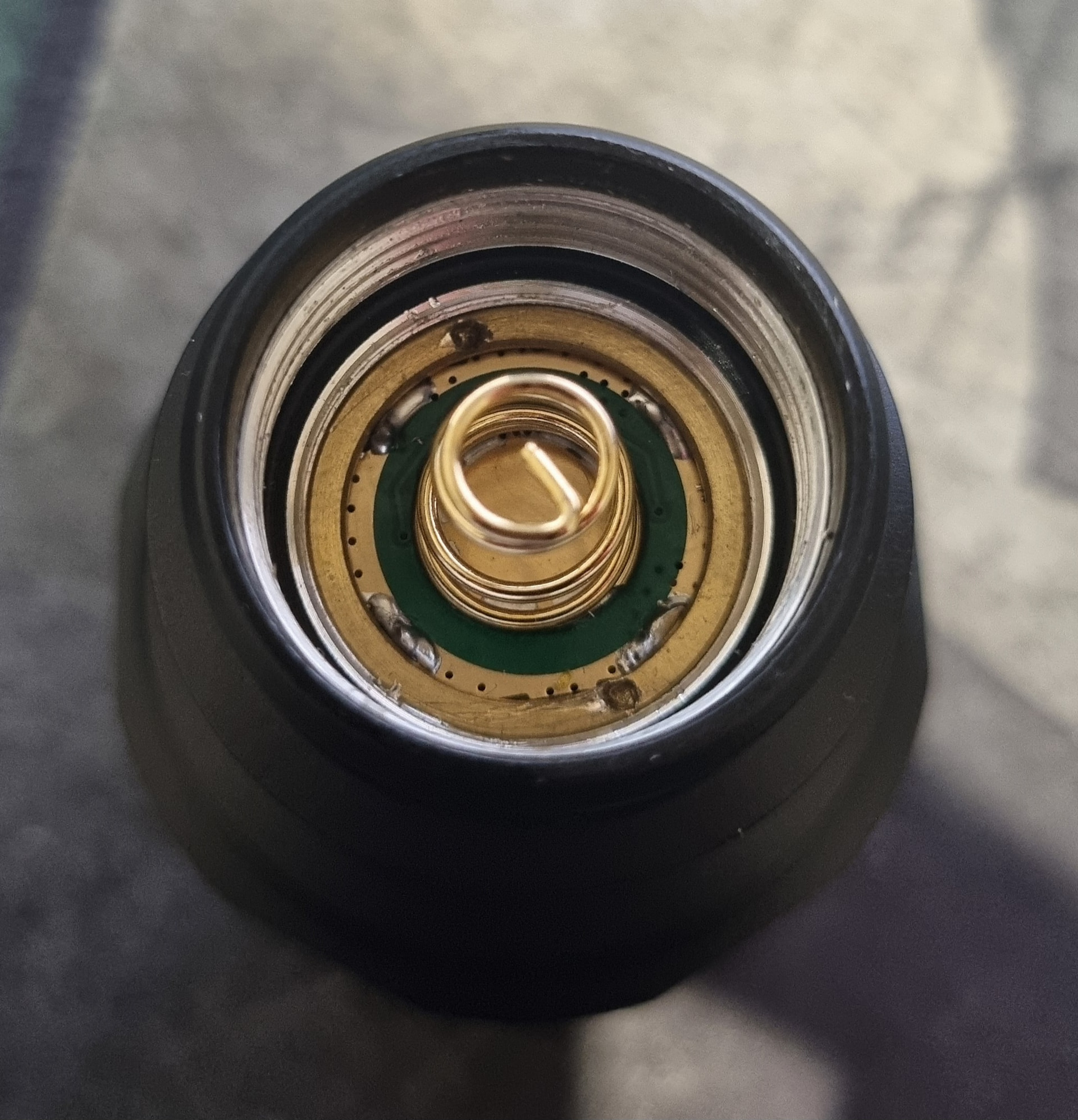
Anyone else receive a host or an assembled C8+ with solder needed on the driver for the retaining ring to make contact? Had it on heaps since mid last year, just since the most recent and current batch. Retaining ring is same thickness as previous batch, it’s the host, maybe the threads don’t go down enough to tighten all the way, I can see a slight gap. Quick fix, but extremely annoying. Had one unit work for 5 minutes and then shut off never to work again until adding solder.
Edit: Just opened my new box to see this issue has been fixed with a new retaining ring.
Ahh, my most recent box of C8+'s have a slightly wider retaining ring, looks like that has already been sorted. The box before it had most of them either soldered at the factory or just straight not working, with the one odd one out that worked for 5 minutes. That’s reassuring to see the updated retaining ring. Same PCB thickness, just to answer your question.
Previous ring = 1.6mm thick
New = 1.4mm thick and a wider contact base
Thanks, I would have never thought to look at the retaining ring. I would have added solder to all units otherwise, saved me a lot of time.
Stiff or double spring lights tend to deform the battery top in high G situations (aka if you drop the lamp). But I would imagine hard mounting it to a gun would also cause serious G forces and maybe damage the cell if the battery spring is too stiff.
Haven’t seen this idea considered, but would combining a small, not-so-stiff spring with a traditional wire bypass be a solution? It takes care of the space issue on the driver, prevents denting of the battery, while still allowing for good current carrying capacity. Have the spring serve a mostly mechanical role and have the wire do the current carrying.
I sell these models with button top cells only. The double springs shown aren’t stiff, they compress with little force, not much more than the large spring on its own.
Ah I see, it is pretty technically demanding work even without the tremor!
It might help to bypass the wire outside the cylindrical body of the spring; I find it much easier than trying to cram the whole thing in, and over time these external bypasses also held up better mechanically in my experience.
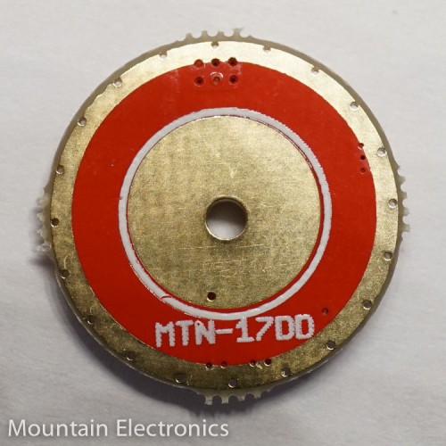
I like MtnElectronics’s solution, which is to have a hole in the middle of the PCB to push the bypass wire through. It would be nice if Simon could design driver PCBs like this.
Bigger, yes, but a tiny donut hole in the middle, unlike the LHP73B. And you can see that the LED is square, the beam looks a bit qeird and isn’t completely round, it’s more like a 97% rounded off square.
But the Tint on that 5500K… maaaaaan so nice
will using a steel or titanium 18350 tube reduce current to the emitters? since these are very bad conductors. asking for an S3 with LHP351. I want the full 10A to reach the emitter
Think the question would be whether the 18350 can sustain the 10A for long term. Its why I’m running a 18650 with the steel body and LHP531. Wasn’t brave enough to pair the 20A driver with LHP73…

 no need to reflow manually now.