I have BLF17DD’s piggybacked into both of mine. The MT-G2 one is using 6 Efest Purple 18350’s, that one has the switch pcb raised to allow room for the double cells in each bay, so it won’t take a switch.
I’ve got the reversing UI on both of em such that Turbo can be reached from off as easy as Moon. Being able to turn it off from the tail on my XM-L2 version is very nice, really have no clue why I didn’t think of that…
I used an UCLp from flashlightlens.com, the best AR lens in the business. Their UCL glass lens is hands down the highest transmission lens out there, but not available in the size for the Courui D01. Crazy as it sounds, there’s a massive jump in throw for the money spent. From 341.5Kcd to 369.25Kcd by swapping the lens.
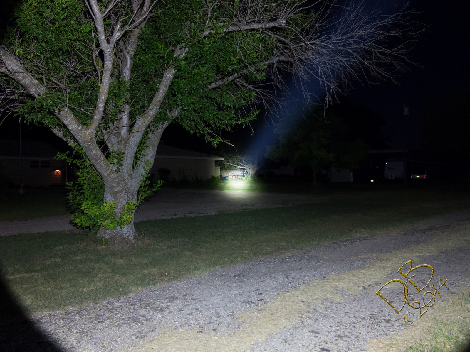
97 yds to the red oil drum. Taken with my standard settings from the Canon G1X…ISO1600, f/5.6, 1/2 second exp., manual mode, manual focus, 2 second timer.
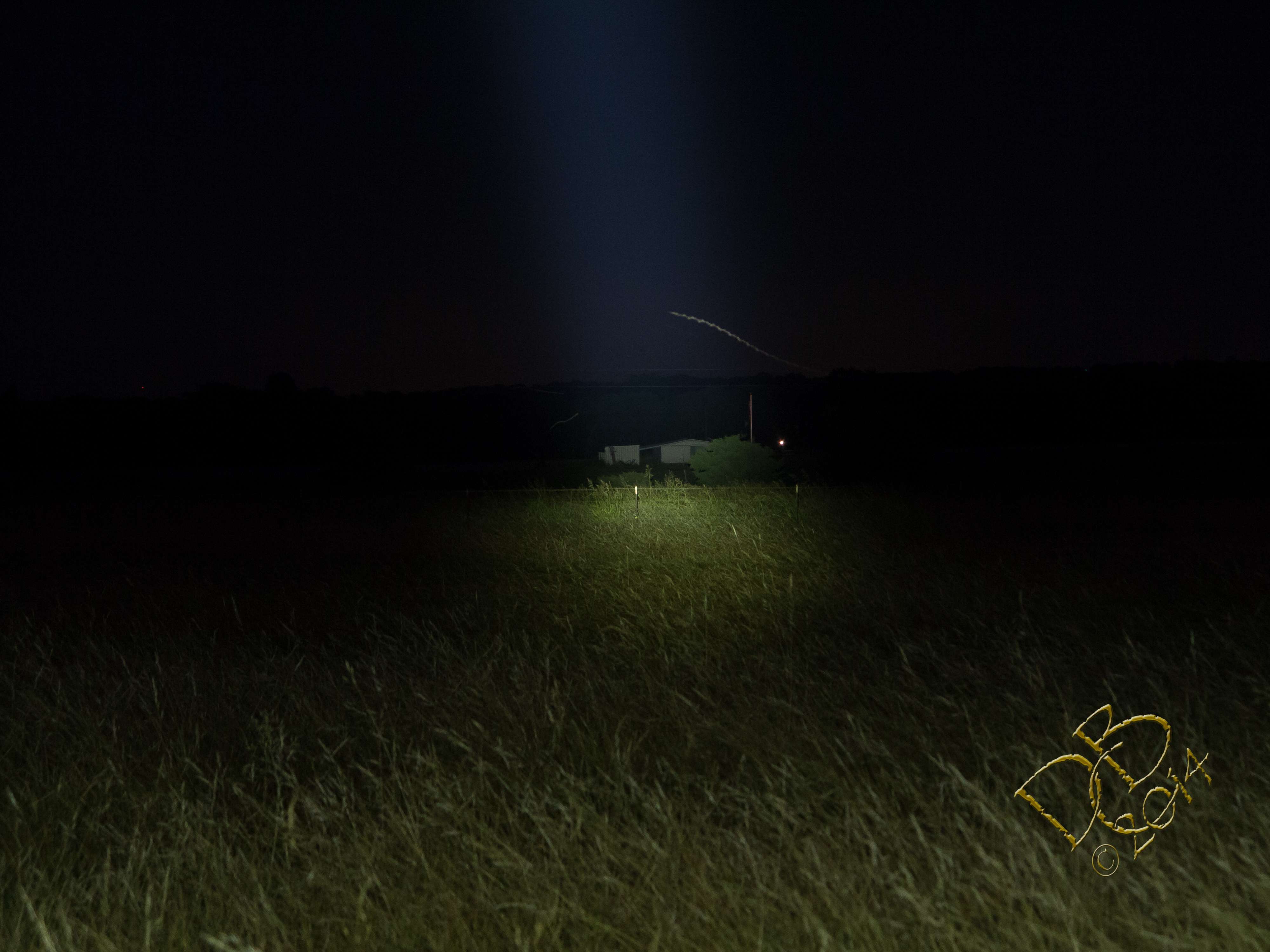
same settings, except f/5.8 and 610 yards to the white barn… if you click on the picture and look at it full size, the trees behind the barn are 744 yds away. Not sure if the white metal building at 968 yds shows through the trees in this shot. (slightly right of the barn and of course behind the trees, only slightly visible as some white above the barn and just left of the flag pole. This is more visible in the winter when there’s no leaves on the trees.)
Excellent work and information FmC. Think you may eventually take this baby up to 5+ amps? You certainly have everything in place (32mm copper DTP mcpcb, etc).
FmC, I must be missing something then, thank you for pointing out.
DBCstm, thanks for your explanation. I did read that by bridging the sense resistor just like that could affect the modes and the on/off operation, but I thought that is just for buck driver. I don’t think Courui in this case is having buck/boost driver since it is three batteries in parallel powering a single XM-L2, though the big torroid on it still makes me wonder what is it for actually.
Thanks Dale, I might have to check out those lenses for a few of my lights…
@ ImA4Wheelr, It’s gotta be close to 5a to the LED as it is, which is pretty much in the sweet spot for XP-G2 according to djozz’s testing work. & I like the basic UI in a light of this type, with the stock driver.
I got some XP-L’s in the mail today, so I think one of those will end up in my other Courui when it arrives, along with a BLF DD driver for a Big Brother version
Your mods look perfect for someone looking to make a true budget thrower.
Does anyone know if replacing the R200 with an R10 would provide enough resistance so no “moonlight problem”
but still give close to maximum output with the stock driver?
It is probably going to be trial & error to find the lowest resistor value that maintains an ‘off’ mode. Maybe someone will find out what that value is & post.
If I had a 20-50 ohm variable I could measure current draw on high with R200 bridged,
solder some 24 gauge wires between it and the R200 pads and adjust it until the LED went out,
measure current draw, IF acceptable then . .
unsolder and measure the variable,
find a SMD resistor of a slightly higher value and solder that in.
OR do what is suggested above with a 10K resistor. It might be a better solution.
What is a good source for SMD resistors outside of the USA?
Somehow I missed the R in front. Won’t happen again.
I’m from the Bad Boys Roust Our Young Girls But Violet Gives Willingly days.
Black, Brown, Red, Orange, etc
SMD is a different world.
Think a 1 ohm variable would be a useful item when modding stock drivers?
We've used trimpots before in mods, like this 10 ohm one, described accurately in a review: http://www.fasttech.com/reviews/1224400/2408 for flashlight modding. One problem is the sheer size of it.
I’ve been waiting to see someone add that missing switch
One tip for the negative to the driver; you might think about adding a thin spring to the outside of the driver.
Something like a wave-washer may do the trick depending on clearance.
As the driver is only a press fit, you really need something there for a solid earth.
I just had a quick measure, & if a washer was used, it would have to be 43mm OD, 36mm ID, & you’d still need some small solder raisers (on the driver side of the ground ring), as the driver is slightly thinner than the shelf it sits on.
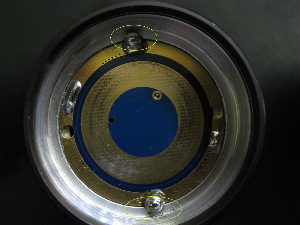
I’m planning to drill & tap 2 holes in the positions marked in my picture above, to secure the driver.
The thing you have to watch is to keep the screws level or below the driver surface…otherwise they can push a cell up and keep it from making contact so you’re only using 2 of the 3 cells.
One trick I’ve seen in my cheap lights where the driver was pressed into an aluminum pill was to “crimp” a solid copper wires between the driver and the vertical wall. The wire would be soldered on the “farside” (x2) and pressing in the driver flattens the wire and the aluminum is “stretched” out some (thin sidewall). It is pretty much equivalent to having a driver with plating on the edges. Foils would be a good alternative.
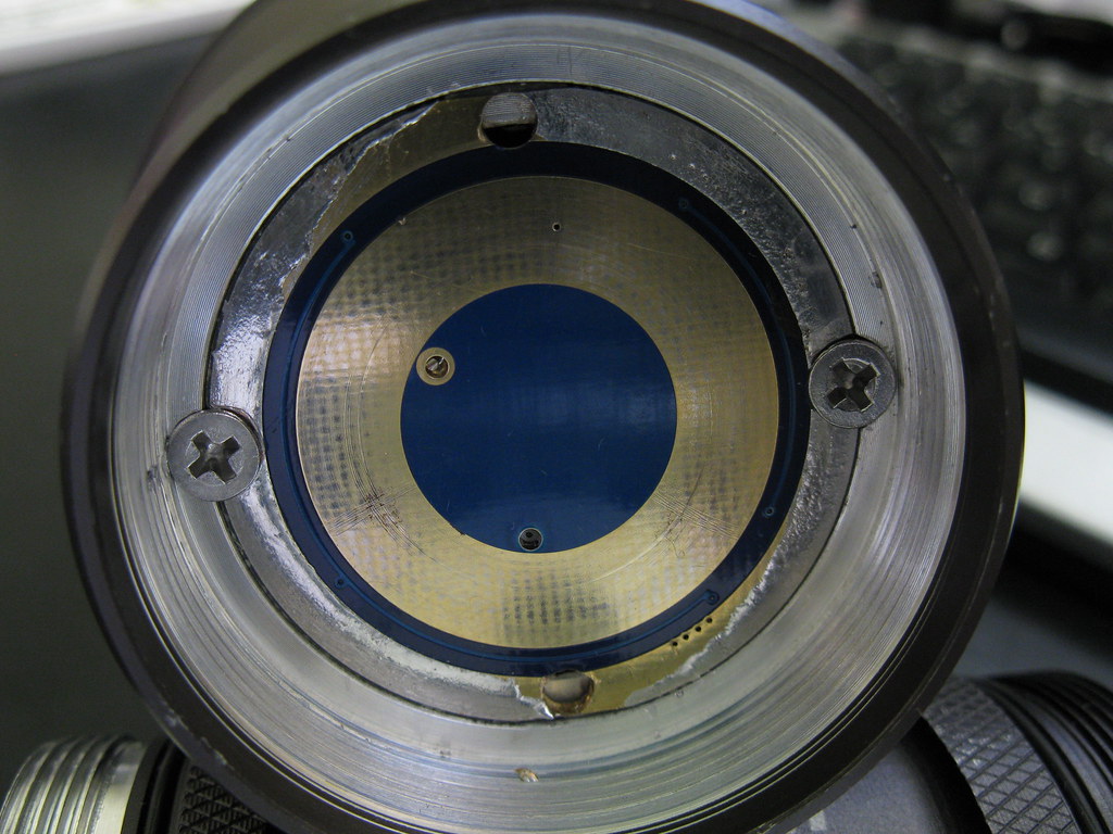
I got around to securing the driver with screws this morning;
With the driver in place, I drilled a 2.75mm hole through the center of each 'ear' & into the body to about 6mm depth, then followed through with a M3 * 0.5 tap.
To get the screw heads nice & low so as they don't interfere with the batteries, I chamfered the hole with a 5 mm drill.
Nice solid earth connection, & easy to remove the driver.
 .
.