Thanks Dale, I might have to check out those lenses for a few of my lights…
@ ImA4Wheelr, It’s gotta be close to 5a to the LED as it is, which is pretty much in the sweet spot for XP-G2 according to djozz’s testing work. & I like the basic UI in a light of this type, with the stock driver.
I got some XP-L’s in the mail today, so I think one of those will end up in my other Courui when it arrives, along with a BLF DD driver for a Big Brother version
Your mods look perfect for someone looking to make a true budget thrower.
Does anyone know if replacing the R200 with an R10 would provide enough resistance so no “moonlight problem”
but still give close to maximum output with the stock driver?
It is probably going to be trial & error to find the lowest resistor value that maintains an ‘off’ mode. Maybe someone will find out what that value is & post.
If I had a 20-50 ohm variable I could measure current draw on high with R200 bridged,
solder some 24 gauge wires between it and the R200 pads and adjust it until the LED went out,
measure current draw, IF acceptable then . .
unsolder and measure the variable,
find a SMD resistor of a slightly higher value and solder that in.
OR do what is suggested above with a 10K resistor. It might be a better solution.
What is a good source for SMD resistors outside of the USA?
Somehow I missed the R in front. Won’t happen again.
I’m from the Bad Boys Roust Our Young Girls But Violet Gives Willingly days.
Black, Brown, Red, Orange, etc
SMD is a different world.
Think a 1 ohm variable would be a useful item when modding stock drivers?
We've used trimpots before in mods, like this 10 ohm one, described accurately in a review: http://www.fasttech.com/reviews/1224400/2408 for flashlight modding. One problem is the sheer size of it.
I’ve been waiting to see someone add that missing switch
One tip for the negative to the driver; you might think about adding a thin spring to the outside of the driver.
Something like a wave-washer may do the trick depending on clearance.
As the driver is only a press fit, you really need something there for a solid earth.
I just had a quick measure, & if a washer was used, it would have to be 43mm OD, 36mm ID, & you’d still need some small solder raisers (on the driver side of the ground ring), as the driver is slightly thinner than the shelf it sits on.
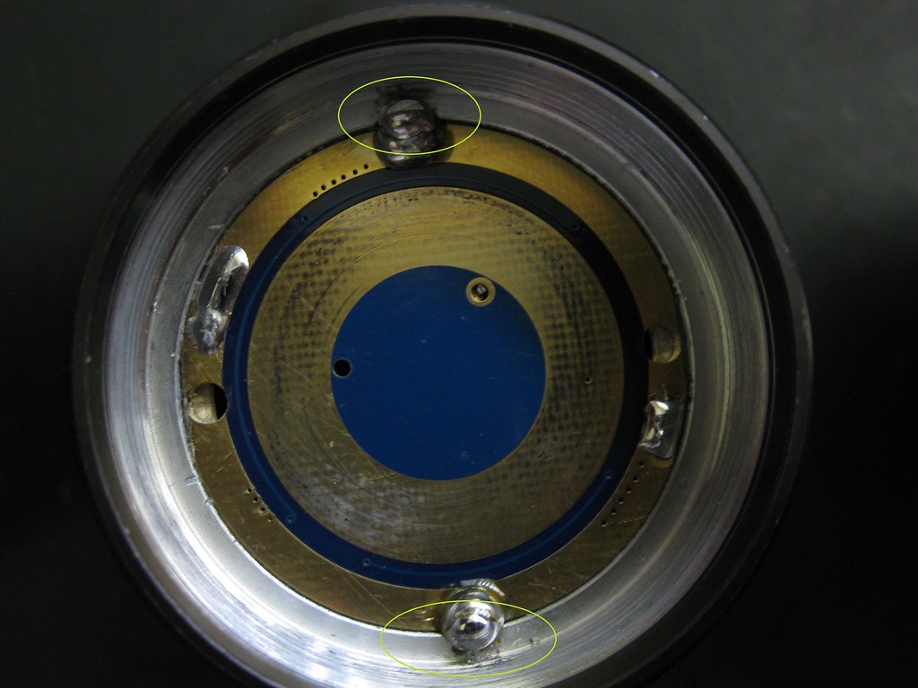
I’m planning to drill & tap 2 holes in the positions marked in my picture above, to secure the driver.
The thing you have to watch is to keep the screws level or below the driver surface…otherwise they can push a cell up and keep it from making contact so you’re only using 2 of the 3 cells.
One trick I’ve seen in my cheap lights where the driver was pressed into an aluminum pill was to “crimp” a solid copper wires between the driver and the vertical wall. The wire would be soldered on the “farside” (x2) and pressing in the driver flattens the wire and the aluminum is “stretched” out some (thin sidewall). It is pretty much equivalent to having a driver with plating on the edges. Foils would be a good alternative.
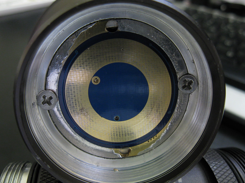
I got around to securing the driver with screws this morning;
With the driver in place, I drilled a 2.75mm hole through the center of each 'ear' & into the body to about 6mm depth, then followed through with a M3 * 0.5 tap.
To get the screw heads nice & low so as they don't interfere with the batteries, I chamfered the hole with a 5 mm drill.
Nice solid earth connection, & easy to remove the driver.
Hi guys, as predicted something went wrong with my 2nd mod
I replaced the led driving wires with 22 size. All was ok, apart from I couldn’t remove the driver board (glued in hard) so I had to do it all in situe.
I did it all fine, but there are 2 problems.
the thicker wire rubs on the bottom of the reflector now
I only have about 20% of the power I previously had!
I think I have found why, but would like someone to confirm.
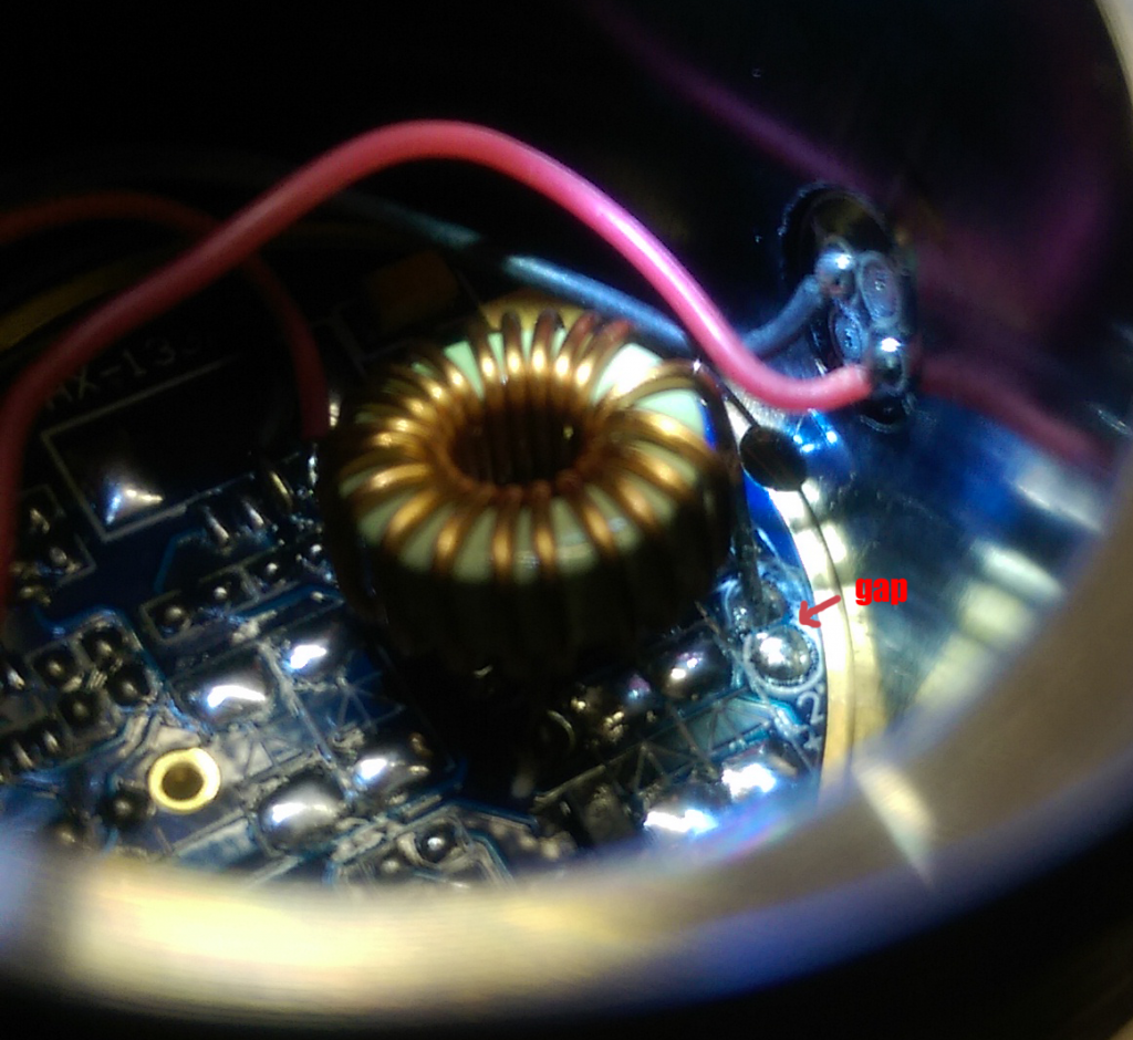
I have seem a lot of pictures of the driver board, and on eevery one the wire bound component is soldered to the live wire - mine seems to have either come un soldered (though it is still soldered in place, just not touching - maybe it pinged off when i removed the original red wire?) or was never touching in the first place.
I’m lost I admit - any help would be massively appreciated. ( I really don’t think it can be much - I was VERY careful)
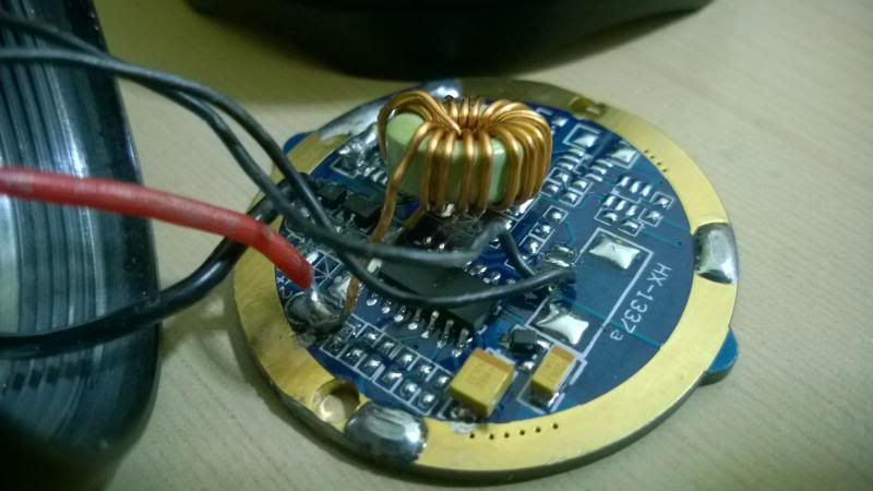
Hopefully you can see what I mean on this photo (not of mine)
I’m pretty sure it’s all one pad there. Can you get some better pictures, with your wires in place.
Also, did you try to remove the driver? If so, you might have disturbed the ground path.
.edit. I just saw your other thread where you mention the wires shorting out on the back of the reflector. That might have something to do with it…. :zipper_mouth_face:
Thanks FmC, I haven’t any pics at the moment, though I decided to go for it and flow them together - it made no difference anyway.
Bridging the r200 which I think was blown worked though, but I am fairly sure it was a little brighter before, though I may be wrong.
One member has very kindly given me a replacement so I will fit that carefully when it comes being sure to check those wires ……
Are those R200 resistors readily available? ( I don’t want like 50 of them lol)
 .
.