You are one of the biggest experts here on BLF that is for sure. Looking forward for your builds...
+1
got mine today ![]()
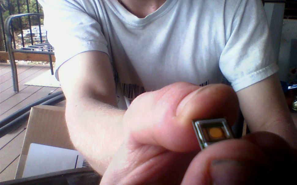
![]()
^One of his flashlights?
Haven’t you told them Linus? (It’s his EDC magnifying lens.) :bigsmile:
The coating sample arrived. Bubble wrapped, in a bubble envelope, opened carefully to find a shattered up plate. It was OK, though. I managed to have two pieces large enough to work with. I tested using individual laser beams at 450nm, 532nm, 650nm, and at 405nm just for a result (LED light doesn’t contain 405nm). Yes, their data is definitely accurate, over 99.6% transmissive at all visible wavelengths tested using a laser meter through the un-coated substrate portion, then through the coated substrate portion. Looks like a very thin coating with little (slightly gold) color as I can see where the coating edge begins on the glass. Some coatings are thicker than others, there’s no real way to measure that, it’s each company’s individual procedure which defines the coating thickness. It is a vacuum process. The glass is very clear plate that you would expect to transmit a lot of light by itself, and putting a round beam half on the coating side, half on the un-coated glass side, you can visibly see the beam brightness increase on coated side after passing it through another lens to diverge the beam to a larger size, each color then aimed at a wall to view this.

OK, they do have Al or Ag mirror process coatings to achieve high reflectivity on a metal reflective aperture surface. I still don’t have official quotes, they need lens or mirror sizes of complete parts to determine how many can be fit and coated in one batch, which I assumed, but I do not have a lens choice for another light that needs it, yet. Mainly gathering more sources at this point. The kicker here, is that for high-end mirrorizing, a single run starts at $750 and goes up from there, from this company. The apertures would need perfect specular finishes before mirrorizing (to make it worth the $ ) or any imperfections will scatter light rays. I have to speak with the machinist to see if this high of quality is do-able with his processes. If a compromise on finish quality is made, it will translate directly to reflective intensity gains of course—and perfect is never a possible goal to aim for.
I’m also going to reach out to a few optic companies to see if they can build a lens to specs with low enough scratch-dig rating on inside finished surface, to obtain quotes for potential reflective aperture starting components. Some more testing will be needed. To produce the components, they cannot be wrong the first try. I will have to prototype them physically at various sizes, check aperture dimensions for exit light angle based on aperture hole sizes, then create final specifications for a reflective aperture intended for a particular lens. It will surely work with other lenses. Optimization for a known lens choice is the main game at this point.
2 ideas i have been thinking of.
Would the output go up if the base of the mcpcb was covered with a reflecting surface, when we use a reflective aperture.
And could we use a light temperature test with an colorimeter or spectrocolorimeter to “focus” the RA, what i am thinking is that maybe the light temperature goes down the more focused & recycled the light gets.
One way to measure color temp with an colorimeter is with Argyll CMS spotread, and you also get a lux reading when you test & if you have an spectro you even get a spectrum curve + an CRI readout ![]()
MEM i think i have said this before but i would be awesome if a custom tuned drop in RA for the UF-1405/1504 platform could be made available.
But i don’t really know, maybe it isn’t really possible to make something, that need sub mm precision tuning with all variables like different mcpcb’s & led combinations.
But maybe if the options where limited to XP-G2 on a noctigon for example for optimal performance.
I’d say output would go up in general but that output mostly wouldn’t be contributing to the central hotspot intensity. Instead it would be visible in the form of an image of that reflective mcpcb. Remember that anything that’s being illuminated around the die will be projected through the lens and show up around the hotspot in the form of (probably unwanted) artifacts.
For example if you have a red noctigon and use an RA that isn’t perfectly spherical or reflective, you will end up seeing some of that red noctigon illuminated around the hotspot. Any stray light coming from objects illuminated by the led will show up in the beam, most of the time that stuff simply isn’t bright enough to be noticeable relative to the die image however.
Yes you are right, i know that it could reflect as artifact but maybe there is a way around this.
And maybe the gain in output would be enough to be worth the possible artifacts, and at long distances maybe they wouldn’t even be visible.
What if the angle of the reflective surface would be slightly lower from the die edge down to the edge of the RA, shouldn’t that make the light be captured inside the RA to be recycled, so much less escapes beside the die as artifacts.
But i maybe thinking about this all wrong, it could be that to focus the RA properly you have to raise it higher than the die instead of lowering it, or maybe it could alter the process of focusing the RA completely, if one would be using an reflective surface at the bottom of the RA.
If you focus the RA properly, there shouldn’t be a significant amount of light hitting the MCPCB, the pill, or any other surface. The RA’s purpose is exactly to recycle the light back to the die that might otherwise hit one of those surfaces. The lens is the only other surface that light should be hitting, ideally. Everything else is waste. Even if normal spill is useful sometimes, it is still considered waste when figuring lux, throw, etc.
Yeah i know that the better focused the RA gets the more light gets to the emitter, but because a perfect RA probably is hard to do, maybe there can be gains from reflecting back that light in to the RA from the bottom that gets lost on the way, because it hits at the wrong angle in the opening of the RA.
Just like MEM found that several lenses ups the throw even when it shouldn’t just because of the imperfections in the lenses become less of a factor when it is shared over several.
You may be able to get some gains by bouncing scattered light back into the RA but I don’t think it’s going to be possible without introducing more beam artefacts at the same time.
I’d say there’s other places when you’ll be able to make more significant gains before that approach would be required. Mainly perfecting the geometry, polish and focus of the RA itself, that will definitely show the big gains first.
On that topic I’ve been playing with my melon ballers again ![]()
Had some time to do a better polish job on the stainless steel collar and am now working on fine tuning the focus. I’m pretty happy with the finish quality, there’s still some deeper “lines” that I wasn’t able to remove completely without starting over with progressively finer and paper but it’s probably as close to a mirror finish that I’ll be able to achieve with the tools I have here.
Not bad for a 4 dollar part at all, very pleased with it in fact. And it get’s noticeable less hot now so my light recycling efficiency has definitely gone up some.
Process was as follows in case anyone is interested.
1. Brown polishing compound on a felt pad bit spun in a basic cordless drill. Lots of pressure and drill set to high speed.
2. Blue polishing compound on a different felt bit.
3. Hand polishing using Mothers Mag&Aluminium polishing compound on a microfibre cloth. Again lots of pressure to really bring out the shine.
4. Finally I used some Vienna Lime powder to soak up and remove any remnants of the polishing compounds. Very satisfying step as the mirror finish comes to light ![]()
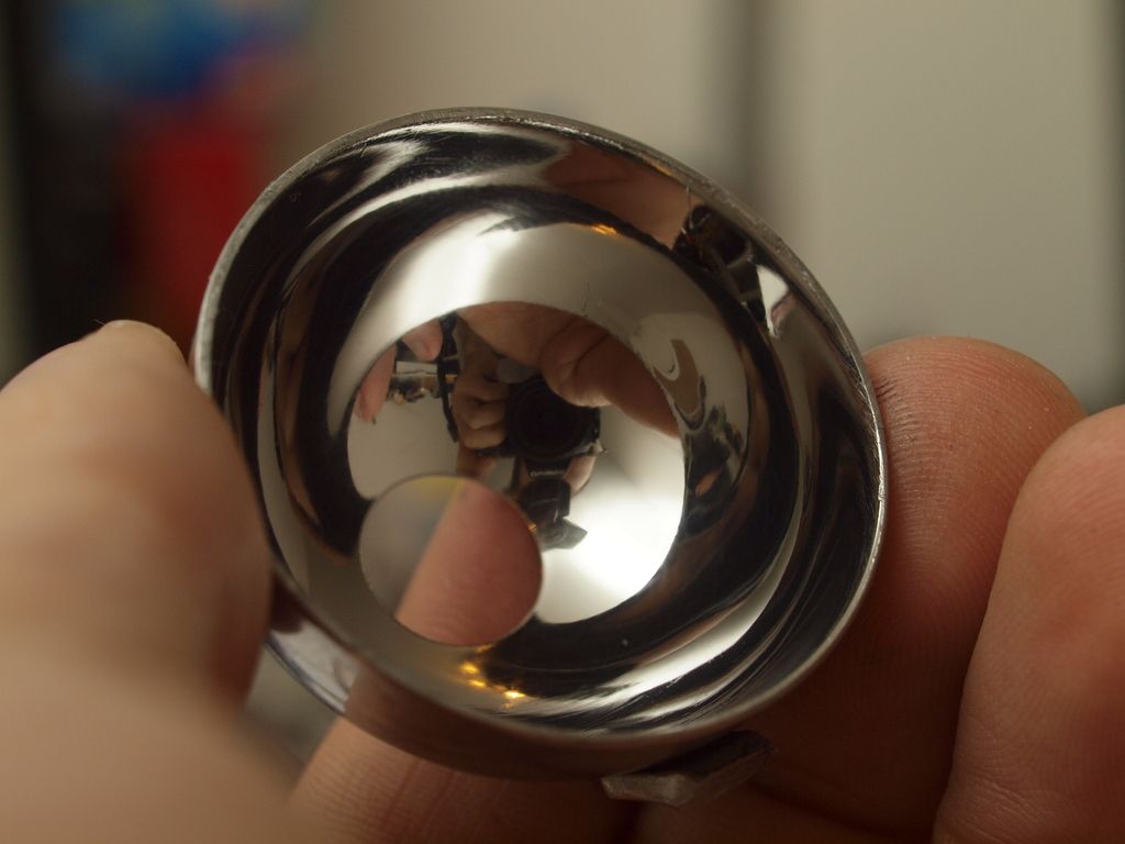
I also sanded the opening of the collar flat to remove the circular artefact that was visible around the hotspot. I actually noticed that I need to open the hole a bit more to ensure I don’t cut off light at the edges of the lens, at the moment I’m seeing 25% improvements without trying too hard with the focus of the collar. But I’m hoping for a bit more with the aperture opened up to fully cover the lens edge to edge. Not sure how much I’m losing here at the moment but I can clearly see that the edges of the collar opening starts partially obscuring the led before reaching the edges of the lens, that’s obviously not helping.
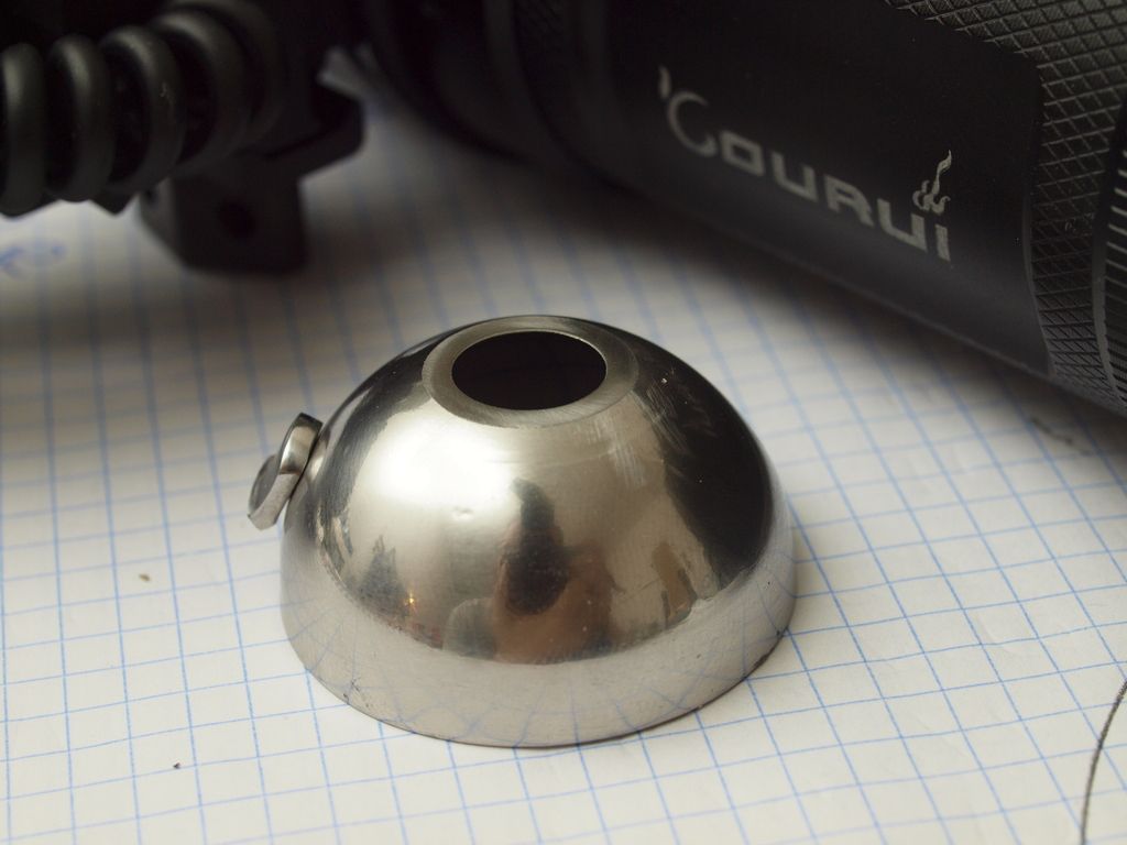
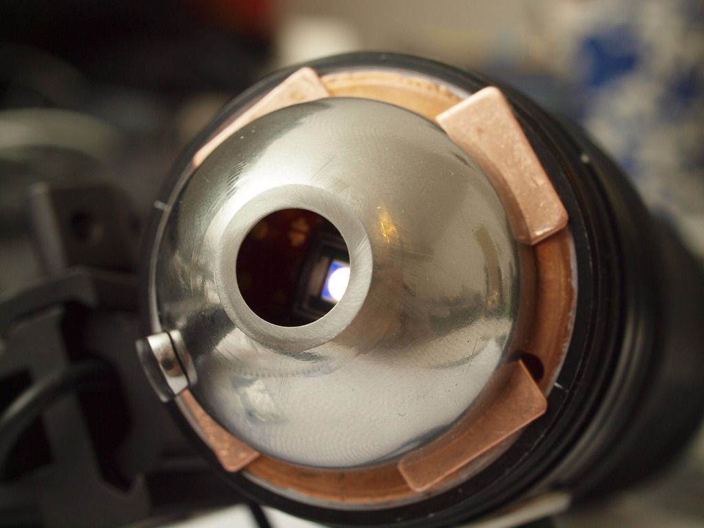
If all goes well I’m optimistically hoping for an end gain of about 30% with this particular collar. We’ll see.
Thanks for the update Linus ![]()
Looks very shiny, i like to use an ultrasound washer to get stuff really clean, if you have access to one maybe test that to get an even higher shine, but maybe the Vienna Lime powder is enough.
You have obviously done your research on this & i haven’t yet, so it was interesting to know some of the steps required.
I hope i can find a cheap similar RA that will fit the smaller 1504 ![]()
The lime is pretty spectacular in removing the waxy/greasy residues. Works way better than trying to clean it with say a microfibre cloth or alcohol swabs, it’s quite impressive. I’m sure an ultrasonic cleaner would do an even better job, don’t have one though.
I don’t know much about polishing but I ordered a kit on ebay and had a go, it’s fairly labour intensive and can be a bit frustrating at first but it’s really satisfying when it starts producing good results.
I think for the second cup I’ll take it right back with various fine sand paper to remove the faint scratches before polishing, see if I can get any improvements that way.
I haven’t torn apart a 1504 yet so don’t know the max size that would fit. Have you looked at other melon ballers that might work? Or tested other approaches?
I haven’t gotten mine yet, i got the shipping notice today, so i will wait before i get it to make some measurements, so i know what room i have to work with. But i think it is narrow, because the mcpcb is only 16mm for such a big lens light.
Have you thought of trying to find some small meniscus lenses to use as the first stage like MEM does? If i haven’t missed something vital i think he uses
LED>AR>meniscus lens>aspheric lens>and optional even bigger meniscus lens. And all the steps sounds like it has an additive effect on throw, i mean you don’t need all but the more of them you use the more throw you gain.
But still the biggest problem with that approach is it think you need, a very good handle on the underlying calculated values of lenses needed.
And so far that aspect eludes me ![]()
I don’t think I’ll pursue the additional lenses at this stage.
I was playing around with some simulations to figure out what’s what. Very useful to get a better idea of the calculations and relationships involved.
I think I have a decent idea of what I could do with a second lens but they’re relatively expensive things to play around with and I’m not really sure it’s worth the hassle.
I’m more interested in focusing on the diy collar stuff at the moment since they’re pretty straight forward to implement and gains are pretty large.
Also all this mucking about with throwers has give me an itch to build something floody again so I’ll probably focus on something like that soon. ![]()
My favorite side effect of the collar is a complete lack of spill or nasty rings in the output. No stray light going anywhere it shouldn’t. ![]()
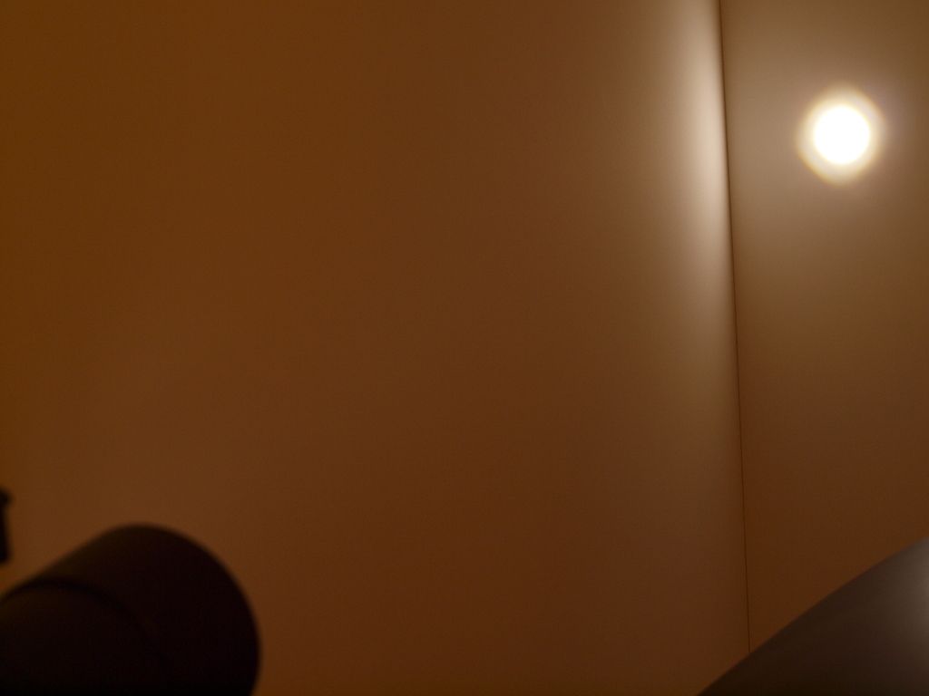
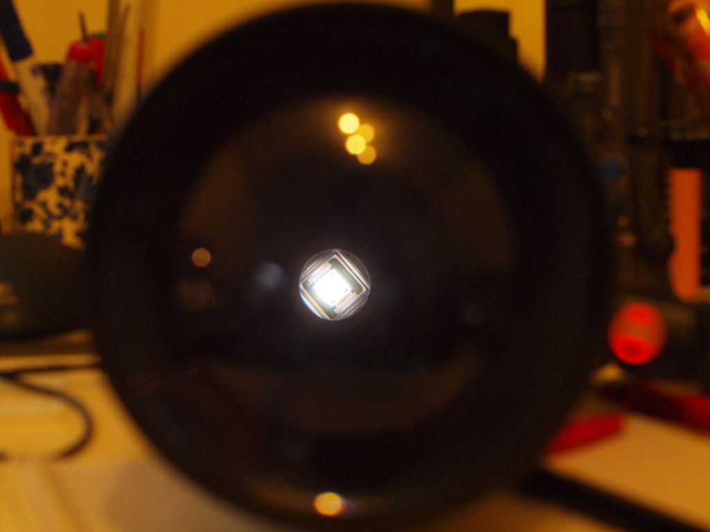
This kind of thing probably only bothers me though ![]()
Let’s see some beam shots
