Creating a custom watercooled led light ... struggling

Wanting to approach nighttime surfing started investigating my options… All being really expensive…
So started reading up on LEDs and drivers and water cooling and so on.

The initial iteration was using a CXB3590 from Cree. Went for a reflector style model but ended up not wanting to purchase and retrofit an existing reflector so tried 3D printing an tried different type of reflective sprays.

The heat from the COB turned out to warp the closest part of the 3D printed reflector.

Read up on high bay LED applications and that the sweet spot is to use different beam angles and values closer to 5 - 10 degrees so really using a reflector for a large COB chip wasn’t a great idea to start with. Learning by pain?

So next iteration was using smaller LEDs and optics.
Haven’t really figured out the proper beam angle for the location where I’m planning to do nighttime surfing so found optics with the same form factor but many different beam angles that could be tested out later on.

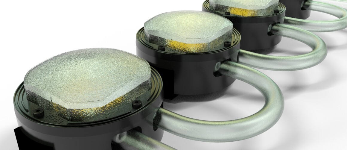
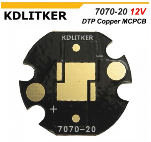
So wanting to come close to 200.000 lumens I found a LED chip Cree XHP70.2 on MCPCBs from KaiDomain.
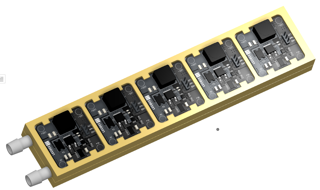
Ordered 10x to start with. Looking to build 4x “flashlights” using 6x LEDs and drive them a bit over spec using water cooling.

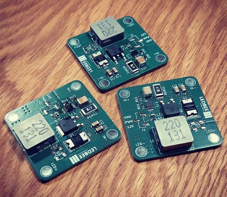
Now to the driver part. Looked at existing options but came to the conclusion (mistake…) of rolling my own…

Went for a 1-1 to achieve a “simpler” more low-amp board … So one driver per LED…

Investigated further and locked on the LM3409 from Ti since they always have great documentation.
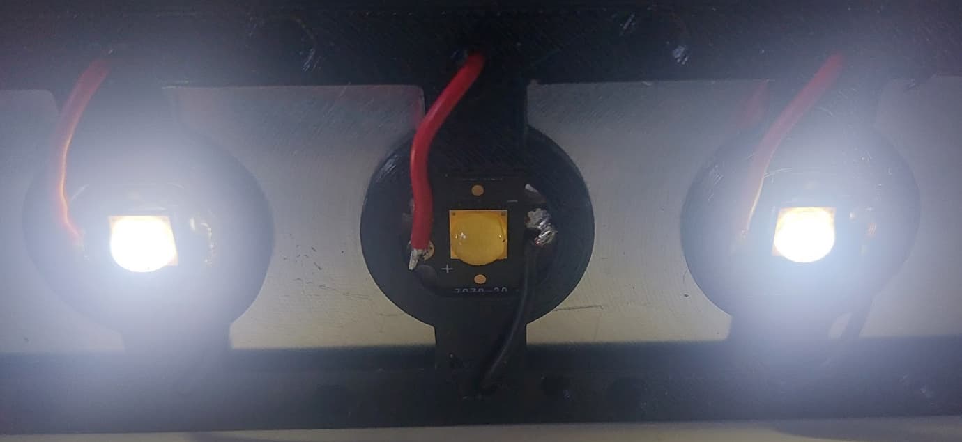
I’ve built 5 sets of drivers and tested them individually and they seem to work fine. But my problem now is when I mount them all in my “flashlight” housing I’m experiencing an issue I haven’t been able to resolve.

Long into…

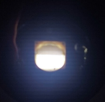
Once mounted, I control each driver/LED using a dedicated PWM signal from my MCU … But when I turn on LED #1 all of my LEDs light up…

I’m using a Polycarbonate (PC) filament and I’m trying to figure out if that PWM signal is somehow traveling via electrical properties in the “plastic”. But at the same time statements about PC filament is “It is also a good electrical Insulator so you can use it to design Electrical instrument boxes.”

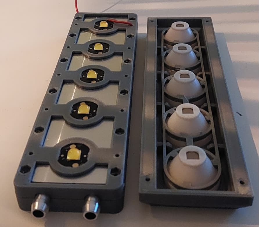
But as soon as I loosen my 3D-printed housing things work as expected… So strange…

I initially printed the housing using PLA but the MCPCBs get hot and deform/warp the PLA parts that hold the MCPCBs against the cooling block…

Any ideas on steps to troubleshoot? Looked for other filaments to try but PC is hard to beat for it’s heat-resistant properties…

2 Thanks

Also tried the Ledil fresnel lens with the CXB3590 COBs… A rendering of that build :slight_smile:

Turns out the fresnel lens with its 35 degrees wasn’t near narrow enough…

1 Thank

Here is how I mount 5 of the drivers using the 3D printed housing with the lid off…
LEDs on the MCPCBs are on the otherside pushed against the water cooling block.

The drivers are really separate PCBs and pressfitted with those small “tabs” pushing them against the cooling block with thermal silicone pads in between to isolate but still allow heat dissipation. PWM is middle pin on that 3-pin header…

1 Thank

Welcome to BLF frippe75 !

That’s a very interesting project.

And an equally weird problem, have you tested everything wired up outside of your casing ?

Welcome on BLF, nice work !

Yes that’s the thing. At least two of them. Then I built another three. Due to heat (the LEDS heat up instantly to 80-90 degrees without contact with the water cooling) I’m really reluctant to running them “unmounted”.

Could be that their is an issue with those later drivers… I did make a design mistake leading to have to disassemble and unsolder a lot of things to replace parts. Bad idea at this stage when troubleshooting…

The “current” suspects…

1 Thank

Running the wires between the drivers and the MCPCBs through the housing complicates the replacement of parts suspected with failures…

1 Thank

Did you verify if the other drivers that should be OFF are actually ON or if they are OFF and it’s a problem with the LEDs wiring ? Are the XHP70.2s configured for 12V ? did you check that there is no continuity between the MCPCB copper base and the anodes ? Also I think kaidomain 12V DTP MCPCBs have the middle connection going through the DTP pad :

+__>|__>|__base__>|__>|__-
Which means that that the bases and heatsink would be at 6V, on the other (supposed to be OFF) LEDs, half of the dies would be lit.

LED wiring is consistent. Would be if kaidomain mounted the LED incorrectly on the MCPCB. Will check.
Yes I’m using 12V XHP70.2.

Checked one of my spare MCPCBs with mounted XHP70.2.

Measured and took a look at kaidomain again. The center pad is not connected. So only for heat dis.

But…

And doing PWM with a value of 1 out of 255…
Adjusting my exposure …

image

Looks a lot like half of the dies are lit from what I can tell…

Is the presoldered LEDs from kaidomain in 12V on a different MCPCBs from ordering them separately or am I really missing the point here :frowning:

Or not providing enough current to turn on them evenly… Maybe increase current a bit and see if I can get a decent shot …

The power resistor controlling max amp of the driver is set to about 3.75 amps currently …
So I’m not providing more than maybe ~20mA

Are you sure ? The picture clearly shows the middle connection (between the two strings of two series dies) going through the middle pad, which says DTP, check continuity between kne of those two small pads on the same copper area as the middle pad, and the base.
You can also check by connecting the LED with one wire to one LED pad and the other to the base.

Which is consistent with a non neutral (6V) DTP pad

A proper 12V DTP MCPCB with neutral thermal pad looks like this : 20mm MTN 7070 DTP Copper 12V MCPCB - XHP70 Series
See how the middle conection doesn’t go through the center pad, here they used a jumper to handle the crossing traces but on larger PCB the middle connection will usually go around one LED wire pad.

Ahhh… I totally get it now. I paid zero attention to that… Thanks @thefreeman!

Glad that the issue is identified, and it’s not entirely your fault, this is a badly designed MCPCB, which is entirely not suited for flashlight use (despite kaidomain mainly selling flashlight stuff) since in the vast majority of flashlights the body is batt-, and that drivers usually use low side current sensing (as opposed to your LM3409 based ones using high side), which means that the LED ends up with only 2 dies (6V) shorted to batt-, with no current regulation, these bad MCPCBs have made a few non working mods and sometimes killed some drivers.

Ordered an initial set of 12 bare MCPCBs … El Cheapo will move the Cree LEDs from the kaidomains to the new ones :slight_smile:

Ok so could also explain the failure I’m seeing in one of the drivers…

And later on, I’m thinking of using the same driver with a slight modification and run two 12V LEDs in series to reduce the number of drivers needed. My initial batch of drivers have most components spec’ed to allow that… Leading to lower costs and allowing a dedicated MCU PCB to fit without making the case larger.

While waiting for those new MCPCBs I’m thinking of placing a silicon thermal pad underneath as a patch. But thermal performance will be greatly reduced I guess. So more for functionality testing. Also realized search through the forum that the LM3409 has been used in numerous drivers so a lot of good info to go through.

That’s a good temporary solution. Also regarding the LED, the XHP70.3 HI might be worth trying depending on the type of beam you want since it’s more throwy than the domed XHP70.2/70.3.

Indeed since it’s cheap and simple to implement, @Lexel used it extensively in >=2S input drivers, it’s also used in the BLF GT XHP35, and a few others I think ? the downside is that it can’t be used with single cells and that it’s asynchronous, I try to go for max efficiency so I avoided using it, in your case it’s watercooled and higher voltage so it’s less of a concern. In case you’re interested I see that LT and Maxim have a few high power synchronous buck LED driver : Selection Table for Step-Down (Buck) LED Drivers | Parametric Search | Analog Devices

edit : I can’t seem to be able to link it properly, link in plain text :

https://www.analog.com/en/parametricsearch/11448#/d=5344|s25|5351|5573|5574|5349|5357|5362|5345|s3|s5&p5349=20|40&p5344=Yes

The 30A 4.5V to 65Vin MAX20078 looks pretty good.

I too would like to have high efficiency since my lights will be placed on portable masts battery-powered using 12V LiPoFE4 batteries in some type of configuration. Bought 3x 20aH 12V. So will either go for parallel config or stack them for a 24V or possibly 36V setup. The battery is rated for 25amp’s continuous output.

Would like to avoid higher voltages for “security reasons”. Not fully comfortable in that space. Originally one factor going for a 1-1 driver/led setup. But using higher voltages makes for cheaper cables and less loss from the battery on the ground up to the masts.

Also, efficiency leads to lower “system cost” since I need fewer LEDs in total to reach ~200k lumens and fewer batteries or longer-lasting ones at least.

I will definitely take a look at the suggestions @thefreeman! The XHP70.3HI’s are on my radar. When/If I scale up if I get to that stage of the project they are probably a no-brainer.

But 24V is probably reasonable since it looks like a simple component modification/calculation… Started looking into that but since I was stuck on my problem above I kind of parked the project for some time. So really thanks for taking the time to reply!
24V cuts driver costs in half only needing half of the amount (ok, higher rated components probably increase it slightly but…)…

Not really sure my project passes as a flashlight… But hey. Meant to be portable and battery-driven… Giant flashlight :slight_smile:

Interesting option! Also the max20096 which supports two separate channels… So 36V and two channels … That could potentially drive all my 6x LEDs per light… Just that it becomes a high-wattage driver… ~400 Watt…