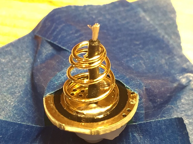
First time soldering anything. It’s a BLF A6 tail and driver spring.
The tail (first pic) spring was a double spring but I removed the inside short one cause I originally planned on doing this on the inside. You can see i got the spring a bit too hot and it deformed slightly. The wire was also too short. Any advice on where to put the wire at the bottom and top when you wrap it on the outside? Maybe some video with a closeup. I want to use silicone wire and not desolder braid.
I took measurements on a 30Q before and after and at “30s” in Ceilingbounce I got 1123 -> 1168 (peak was about the same change 1413 -> 1435). I’m wondering if the bypass is working right, expected like 100-200lm. This is the 5A (4000k) tint version and I topped off the batteries before each test.
It looks like it will be effective. That’s the biggest thing you’re after. When it’s all closed up, no one will see, so as long as there is no cross connection between positive and ground, you will be fine.
For safety reasons, I would put spring bypasses on the inside of the spring. If the solder breaks there is just less risk (especially on the head/driver end). Double springs can also be bypassed, you just have to work more carefully, it helps if you use a coilwinder from ecigs (or any other thin metal rod or pin) and curl the wire around it a few times before using it. This will bring some flexibility and it won’t break as often.
I solder the spring bypass with the spring removed from the driver. That is only logical because I build my own drivers and I also have my hot air rework station. Solder the bypass onto the single/double spring and then solder the spring onto the driver. It’ll be a hassle but worth the effort. That’s on the head, on the tail cap I’d also remove the spring first, drill a hole through the PCB and do a “full bypass” from the contact to the spring, not just PCB. Depends on how many amps you’ll be running though.
The tail bypass could have one suspicious solder joint, but the driver spring bypass looks fine to me.
I care more for the driver spring bypass than a tail spring bypass because a short at the driver is a direct battery short.
I do my bypass usually on the outside as well, but try to clamp both sides of the bypass wire between the spring coils before soldering them (as an overdone safety measure). But the best measure really is to use enough heat and skill so that a proper and shiny joint is made.
Hmm, lessee. A bit derivative of earlier spring bypasses, but good use of color and shape. 3D space is well-used, and while technique might be lacking, the emotional impact of the bypass packs a punch, truly moving the viewer to appreciate…
Oh, wait, not that kind of critique.
Yeah, I like ’em on the inside of the spring. Things break loose, they’re usually kept in the cage rather than bouncing around possibly shorting out stuff.
Need a hot hot hot soldering iron to cook all that metal. Switches are allergic to heat, and ironically, using a smaller iron with less mass makes you heat up everything more than a quick hot get-in-and-get-out will do.
Quickie technique:
Cut about an inch or two of wire (you’ll trim it to size later). Strip one end maybe ¼“, bend the stripped part into an ‘L’, and flux’n’tin it. Feed it down the spring’s ”hole” and rest it against the spring where spring-meets-board.
Put a blob of solder on the iron’s tip, add some paste-flux to the wire/spring junction. Hit the spring/wire/flux with the solder blob, watch it sizzle, once it’s molten and the solder flows, wait a second or two, then remove the iron. Let it cool.
Now snip the wire maybe ¼” above the top of the spring, strip the insulation. Repeat the same tin/flux/solder part on this end.
Thanks posting this and for asking for a critique. Your soldering looks like mine and the helpful comments here have taught me a few things about doing spring bypasses. Thanks guys.
Must say, those solder joints look a little ambiguous…
Not enough heat or not long enough heating, looks like.
But not bad for the first time ever. :+1:
I tend to use 22 or 20AWG, 18AWG is a bit bulky, but will fit inside larger springs like in the L6 or S70S.
So yeah, i put them inside the springs, slightly coiled up so it can compress along with the spring.
When the PCB traces (of either the driver or the switch PCB) are a little narrow or flimsy i look for ways to drill a hole through the PCB for a direct connection to the high current drawing part, like the switch or the + of the LED.
But it’s mainly the springs that need it.
The difficulty is usually preventing the bypass wire sucking up the solder so that it will end up stiff…
So using a hot iron just long enough to get the solder to flow well enough is what i try to do.
First of all, congrats on your first flashlight mod!
Did you remove the driver and switch before you did the bypasses? If not, a lot of the heat of your soldering iron is absorbed by the flashlight head and tail making it hard to solder. And it would be hard to position a soldering iron at the bottom of the springs.
Although a bypass is better than a double spring, I’m not sure it’s going to give you a noticeable improvement.
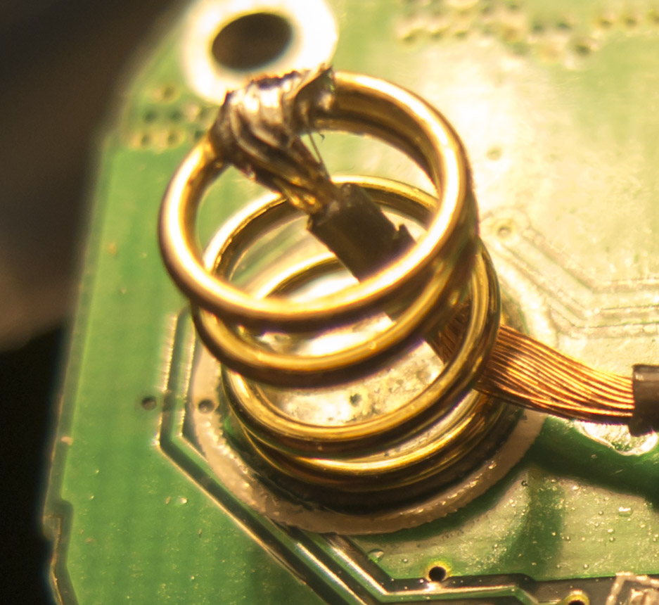
I like to start a bypass at the bottom of the spring. Then curl it a little and cut off the excess. Then get a good amount of solder to form a layer at the top of the spring. Then use a precision tweezers to move the wire into the melted solder. The more contact surface at the top of the spring for the battery the better. Here’s how one of mine looked:
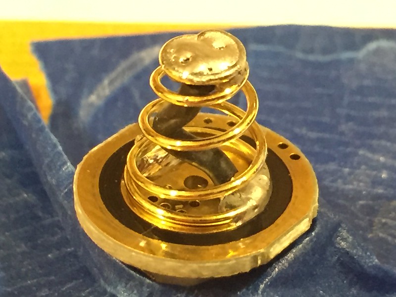
Redid mine in the middle of the springs. Still do not like the way it’s attached to the base of the board/spring and do not understand a good way to make it better without taking the spring off entirely. I did use a little flux paste this time, turned my iron up higher, and switched to a longer pointier tip hoping it would get in the tight spots better.
Only tail pictured and even that is hard to see anything in the pictures but I wanted to follow up seeing as I took advice from the post!