Custom heatsink design for good thermal transfer?

Hi folks,

I plan to mod a Fenix HT32 (21700, white+red+green LED) to accept three LEDs on 16mm MCPCB.
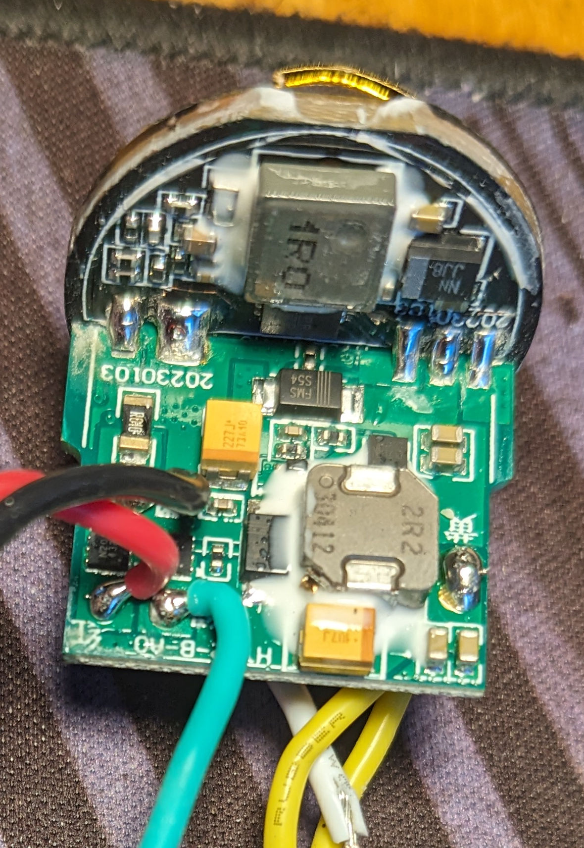
I want to keep the original driver, it puts out 11W - 15W - 17W on white - red - green channels, and 30W on white turbo.

I’d like to have steady 17W output, but even the original setup steps down to a continuous 10W after 3 to 5 minutes.

I drew three heatsinks. They all bring the 3x 16mm MCPCB close to the lens, as I will use individual small optics and aim for a 90° floody beam.
a) a simple round cylinder, 61g, good contact to host with screws. Head needs machining.
b) same, but less material, 37g.
c) this heatsink is only held/pushed by the lens and screwed on bezel. 29g, the head needs no machining.

Playing with thermal resistance, area and thermal paste thickness, I calculated 13K delta for a), 17K for b) and 10K for c). The temperature the LED die is above the host temperature, that is, at 30W (which are, originally, only for a few minutes).
Do these numbers seem plausible?

Looking at the Fenix and 1lumen runtime/temperature charts, the internal delta of LED-to-host doesn’t seem to matter much, as the host itself will heat up so much that the light stabilizes at around 10W output (for 2h).
That would be lower than I wished for. But at least my preferred heatsink c) would be suitable, without machining the flashlight head?

How do these bigger flashlights normally handle 10W, 30W? Would potting the driver, with better thermal contact to the host, help? Is Fenix too conservative with a host temperature limit of 55°C?
Or is 20-30W sustained for 1h simply not realistic without active cooling, in a medium-sized flashlight

Any insights and thoughts are much appreciated!

Ivo

[originally posted on Drehteil, gute Wärmeübertragung? | Taschenlampen Forum and moving here to BLF]

1 Thank

If only the Grey is the only added materiel then. The top portion of “C” for maximum contact on the top half with the base of “A” for mass and the lower contact potion. This will give the greatest mass and heat migration pathway to the host.

1 Thank

Please enjoy your time here, Ivo!

IMO option C offers the most benefit. The more contact to outside air is the critical part. Adding mass like option A will be of some benefit but not lots. It’ll take longer to reach saturation but can’t dissipate the heat well if there is no short path to outside air. It will take longer to cool down as well, partially due to the path of travel but also because of the greater thermal mass.

Whether any of these ideas can maintain the dissipation you want is a good question…

EDIT: one other thing to factor is the thermal control is in the driver (i assume…?). So depending on how close you mount the heat sink to the driver can have an effect as well e.g. if you pot the driver to the base of heat sink A or B there wouldn’t be any benefit since the heat would have a direct path to the driver

Is the driver in the head, or is this one of those lights with the driver in the tailcap?

Assuming the driver is in the head: with heatsink C, the heat path between the LEDs and driver is long, so the temperature around the heatsink will be >55°C, which is fine because the LEDs can handle high temperatures. The driver should not have issues with heat because it has thermal regulation, just let it do its thing. The heat will eventually make its way to the driver and then the regulation will kick in. Adding more thermal mass by extending the heatsink into the head will allow for longer runtime before thermal saturation occurs. Avoid making contact at the bottom to keep the heatpath long. The long heatpath allows for a greater temperature differential to exist between the LEDs and the driver, increasing the runtime before thermal regulation occurs.

I don’t think you’ll be able to do 20-30W sustained for 1h without active cooling.

The SFT-70 is a 6V LED (but also can be configured as 12V), so you’ll be running 3x 6V LEDs in parallel? Have you verified the LED voltage?

Welcome to BLF.

1 Thank

Thank you very much for the warm welcome, raccoon!

texas_shooter:

If only the Grey is the only added materiel then. The top portion of “C” for maximum contact on the top half with the base of “A” for mass and the lower contact potion. This will give the greatest mass and heat migration pathway to the host.

Good idea, which I had a thought about too. The more the better, right? It would be the heaviest solution though, and needs flashlight head machining too. Not sure if the thermal expansion of the heatsink would crack the lens, or if it would be exactly the same as the expansion of the host. It might work better with a cylinder “A”, being wider at the top to transfer heat outward.

pinky, Hoop:

thermal mass, thermal path through the driver

That’s a clever aspect that didn’t occur to me! Dissipating the LED heat without heating the driver would give much longer runtime before stepping down! With “C”, the LEDs are as far away from the driver (and hand) as possible, and the front of the flashlight head has good surface area.

The driver is a regular horizontal disc with the + battery contact, with a second board soldered vertically, perpendicular to it. The horizontal disc is held in place with the thread at the lower mm of the head. The vertical part is freely in the air in the empty space of the lower part of the head. With no contact to the head at all. I assume most of the heat in a driver is from the inductor? Two are on the disc, one on the free floating board.

I could try to thermally couple the driver to the host. Question is, would the driver stay cooler, getting rid of its maybe 5-10% heat dissipation, or would it get hotter, when the host reaches thermal equilibrium from 70% LED heat?
What to use for filling? Epoxy or other glue would be a bit too irreversible for my taste. Some very light, brittle, low-polymerized kind of silicone maybe?

Yes, the time till thermal saturation doesn’t matter much to me. As long as I get a minute of turbo I’m fine. Sure, if the thermal saturation took longer than the battery runtime… :grimacing:

(edit) Hoop:

The SFT-70 is a 6V LED (but also can be configured as 12V), so you’ll be running 3x 6V LEDs in parallel? Have you verified the LED voltage?

I did a lot of measurements of what current each of the three channels can deliver at what forward voltage, if anyone is interested.
I plan to use a “Yingfeng HYB50G45N430AG-X4A” 440nm for the white channel, nominally rated 2A at 6V. On turbo at 4A to 6A, regulated to 30W.
The red and green channels are only good for around 3V (5-6A), at 4V they drop to 100mA. I’ll use a “Yingfeng HYF68X90B365AG-X1” 365nm, and either a SFT-40 or 519A warmwhite high-cri.

Thank you folks!

Ivo

1 Thank

I don’t really know how effective they are but for the driver you could try thick thermal pads. This one i have kicking around is 5mm thick…

1 Thank

You have those in 5mm? Nice! I only have up to 1.5mm or something.
As far as I know, these pads are not too far from regular thermal paste, thermal conduction wise. Normally, they perform worse, because the thermal paste thickness is much less. But in my case, I need to fill a lot of volume anyway.

Thank you for the reminder, I’ll think about it. Maybe that material can be warmed up to become soft enough to squeeze into a void?

Ivo