Not much closer to figuring out why mine won’t work. A bit of testing this morning leads me to believe the top side of the PCB is making contact with the body of the tailcap, thus grounding it out. That would explain why it comes on as soon as I screw down the cap, regardless of switch on/off. I’ll try a bit of kapton tape on the switch pads to see if that helps.
What diameter is that board? And which switch is that? Can the switch tolerate 5-6amp for a single emitter with a DD driver?
I ask because there is lot of spare room around that switch! We could easily fit low voltage detection.
The omten Switches hold easy Up to all the Amp a single led direct drive will see. I guess it is the 20mm and a Stall Switch that is what Makel it Look like a log of spareroom.
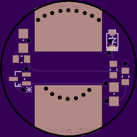
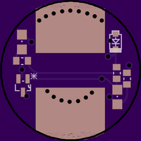
I dremeled away a bit of the soldermask before putting the board in the light to make sure it will never short. Pilot dog has also moved the edge a bit on some newer revisions so that there is a gap between outer board and copper trace.
Yes, I originally had the 1217 switch on this 20mm board, but it was so wide that it would not fit. I swapped it out for the much smaller 1288. I have reduced the diameter to 19mm, so it fits inside that solarforce tailcap. I think it’s an S-12 model.
I can measure the resistance tonight, but if I remember the specs say that both can handle between 1.0 and 1.5 amps. In this particular torch, that won’t be a problem. I’m not driving the LED very hard at all.
I like the idea of cutting back the solder pads, will try that.
I always test the voltage drop on these switches with a power supply and 5A and the voltage drop is 0.1V or so depending on how I have braided the spring…
Very good switches a lot better than any of the preinstalled ones in budgetlights… Check Djozz switchtestthread
Sadly cnqg doesn’t sell the small omtens 5-pack anymore
My transparent caps have arrived, order went through perfect…even the tracking worked.
This evening I made a red/blue led tailboard (latest 17mm version) for one of my BLF-A6 flashlights. 22kOhm in series with the red led, 12kOhm in series with the blue led. I did not install a bleeder resistor on the driver yet.
There's trouble. Mind that the bleeder R is not there yet, but without it (the blue and red led light up, not really bright and) it messes with the BLF-A6 firmware. I have to dig into it a bit more but at least the long press to go one mode backward does not work (I tried all possible delays in case the timing was off). I have two BLF-A6 (5A) lights: if the tail is moved to the other light, the trouble travels with it.
Something with a cap?
Tomorrow I try installing the bleeder resistor to see what that does.
Thanks to DrafterDan’s generosity and his mixed up order from RIC, I now have my first ‘custom’ LED flashlight parts! I have 2 GITD tail covers. If only BangGood had shipping this fast… It almost seems a shame to use these on my lame Home Depot Defiant light.
How smaller parts are people willing to use? I’m going to attempt to design this board. Keeping 0805 LED are we all OK with 0603 resistors? And what sizes for the other components?
My resistors are 0805, they work well for hand soldering (reflowing is not for everyone), I guess I can solder 0603 resitors as well, but it will be harder.
Thanks for willing to design the board, but perhaps it saves the work if we check if the circuitry in practice really works first? The SOT23 transistors are not in yet, so I can not try this yet. But if it is for the fun of designing it, please go ahead, that would be nice anyway :-)
I have check that it follows the same as the schematic higher up. If somebody would check the rest of the layout. I will continue playing with it during the week but I’m away for the weekend.
Well when I was first starting everyone was quick to tell me to avoid acute angles because it could cause errors at the fab. So that’s something you could clean up. And I was also told “Use the thickest traces you can fit.”
Some of the components could probably be spaced a bit further apart to make it easier for the people that use an iron instead of reflow. When I’m working in Eagle on my big screen, I always forget how terribly small all of these things are.
That circuit is simpler than I was expecting. Since most people are using 1288’s instead of 1217’s, we could easily reduce the switch pads and fit full 0805 components (just a thought)