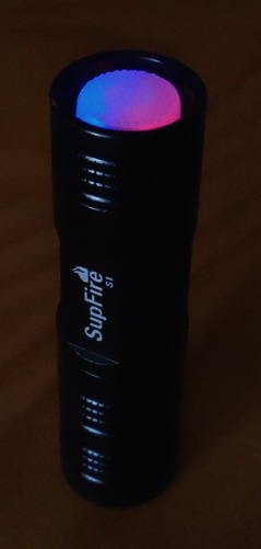
Just changed the leds for my EDC tail, it is red and blue now, each with their own resistor. The red one keeps going during the full battery drain, the blue one dims at 3.9V battery voltage, and stops entirely at 3.8V. I hoped that to be a bit lower so that it was a true low voltage indicator, but this is fun too, a sort of half drain indicator :-)
I’m making progress, but slowly due to my schedule these last few weeks.
I’ve got the cap together, but found that I need to shave a bit off the board diameter to fit inside the Solarforce S12 tailcap. I’m using the 20mm board. The LED’s work, but I may need to play with the resistors. I definitely need the bleeder resistor, that’s my next step to figure out.
I’m just waiting on the clear boots, RIC at CNQ says he may have to re-send the order. It’s been five weeks and no package yet….
This is really cool! Dunno how I missed this. My Roche/Convoy F6 light pipe mod is nice, but this setup brings it to a whole lot more lights, and doesn't tie up MCU ports.
I do too! The only way it would be cooler is if there was a way to make only one LED come on at high (full) voltage, both LED’s on in the mid-range, and only the other LED at low voltage (but above cut-off for lights that have that). With two colors, it would indicate three levels of battery capacity. :party:
As a test I ordered some yellow 805 SMD leds (about the same Vf as red) and some small schottky diodes, see if I can get something in between the red and blue :-)
Gosh, years ago I had a circuit design for just that using I think an LM317 quad opamp. I didn’t know eagle then but still have all the parts to build a few. Still haven’t sat down and worked out how to put it into a light either.
That circuitry is certainly more fancy and precise than simply using the varying led voltages of colour leds to do the job. But it is neat that this quick and dirty method just fits next to the switch.
Resistance is measured in Ohms and was given the Greek letter Omega with the symbol Ω but this is difficult to print so the capital letter R is now used.
Okay, I have a request for the viewers on this particular thread.
CNQG appears to have lost my shipment of the clear switch boots. It’s been 6 weeks, and tracking ends once it hits US shores. USPS is unhelpful.
Do any of the modders of this switch have any spare clear boots to fit a Solarforce tailcap? I think those are the 16mm. I had purchased two packs of both the 14mm and 16mm, so I could mod surefire as well as solarforce tails.
I’d be happy to paypal over some funds, it’s more that I want to complete this build.
I did some fiddling with microscopic leds two days ago, here's the result. Forgive my limited insight in electronics, it's just trial and error here.
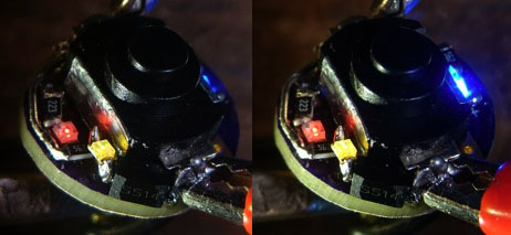
I had a blue and a red led working in my EDC-light (post #280), with the red always on and the blue fading to off between 3.9 and 3.8V, giving a useful half-drain indication. I wanted an extra indication a bit lower so I ordered some yellow leds as well, they have about the same Vf as red, but together with a small schottky diode in series, stealing 0.2V, I reckoned I could get in between red and blue. So a third path was needed on the tail-board and since there were no traces for that I just made the yellow circuitry floating in air (my solder skills are improving by the day :-) )
(stereo picture)
I got it working but like the red one, the yellow led failed to go off at any battery voltage. Then I started swapping resistors for other values, but apart from achieving a better balance between the three colour intensities, it did not change the voltage sensitivity of the yellow led. I tried swapping the yellow led for a white led (an Oslon Square 3500K 80CRI I had around, it is nice and small), but that hardly gave any light at all in this set-up. So I swapped to yellow again and called it a day. I will try with a normal diode next time I feel like testing this out a bit more. The current resistor values: bleeder R: 680 Ohm, R for blue:5.6KOhm, R for red 22KOhm, R for yellow 5.6KOhm (+useless Schottky diode).
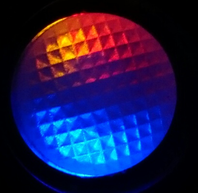
So for now I have three colours from the tail of my EDC, and I can just measure the output: 0.0003 lumen. Sounds like nothing but believe it or not, in pitch dark it is just enough to light my way. So a thing to do in another light is make a permanent moonlight in the tailcap, I have a 3200K 95CRI 5mm led that might be perfect for that :-) .


 (stereo picture)