this thread was initially for the OL contest, but i ended up building somethign else, this thread will be for when i come back to this project to finish it
I’m starting to work on building the tracking spotlight. I’ve done an initial test using my laptop and webcam to do computer vision based tracking, everything else should be standard.
It will be a raspi 4, Playstation 3 eye camera (for an easy IR camera), 2 high strength servos, a sft40 and Fresnel lens and a NIR led and reflector.
I will wear a retro reflective patch, the light will start at a neutral “home” position, once I step into the home location the IR light will reflect off the retro reflector and be picked up by the camera and give it a target to track.
The spotlight will be mounted to a DIY gimbal with a 4:1 gear ratio to give me a range of roughly 40 degrees.
My only concerns are the ease of building this all by hand, and the infrared that will be shining into my eyes to track my position. Otherwise this seems doable.
I haven’t decided if I should do the tightest spot possible or if I should get a initial lens so I can project a larger round spot (like a stage light)
2 Thanks
Sounds interesting, Good luck with the build!
i have two options for tracking:
A. computer vision with an IR camera, flashlight, and retroreflector and it will only work at a set height
B. 4 modules that can measure the distance from eachother, 1 in my dorm, two setup somewhere outside, 1 on me. https://www.aliexpress.us/item/3256801389358822.html as seen here https://www.youtube.com/watch?v=ajKES2dd5BM. these have a 130m range, although i dont know if they can measure distance from 3 different boards at once


Feast your eyes on my side project for I have not yet begun this main build
(I will try order parts tomorrow but I leave university for winter break soon and will lose access to all my tooling)
(As a backup I’ll prepare parts for a more basic machine made flashlight as well as the pictured side project. I will enter something but it might not be the coolest build I’m working on)
ordered the parts for a fresnel thrower + the tracking spotlight, well see what i can finish first/have more fun working on
while i wait ive been working on this lamp some more


1 Thank

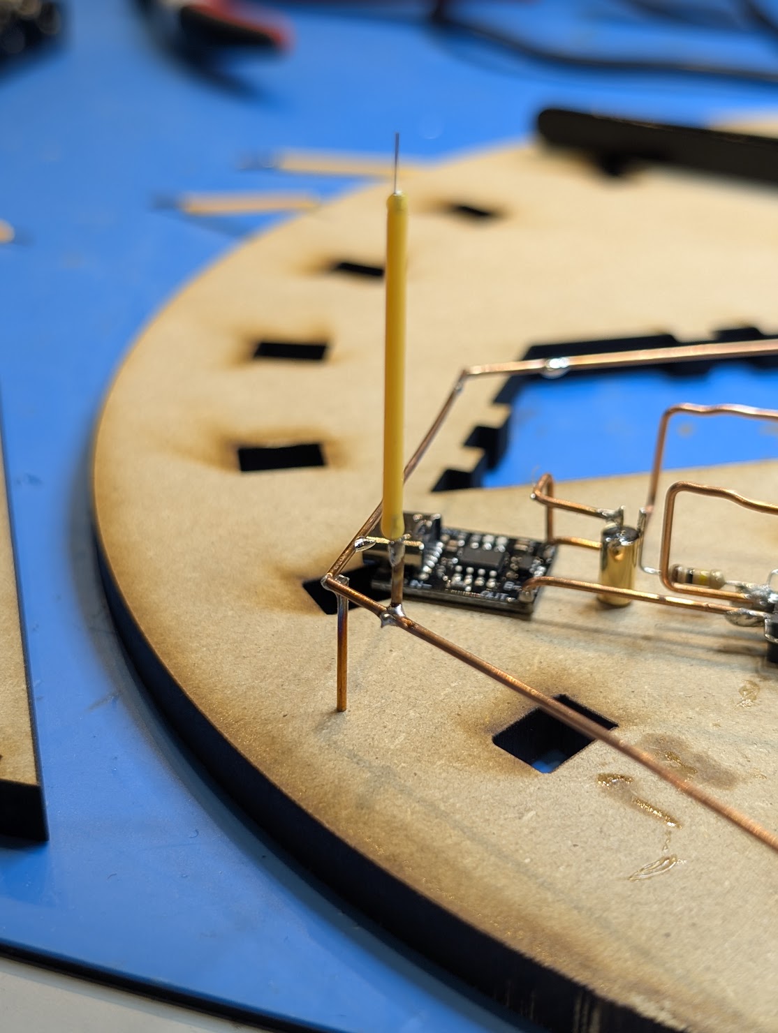
this is the LED ring, all the filament LEDs will be connected in parralel around this ring, the floating copper wire will connect the battery positive (mounted on the opposite side of the lamp) and the battery negative will be brought to the charger board.
had i better planned this i couldve fit everything on one side and maybe made it look cooler, but it wouldve required as much wiring
1 Thank
WOW such old-school circuit building!
I like it
1 Thank

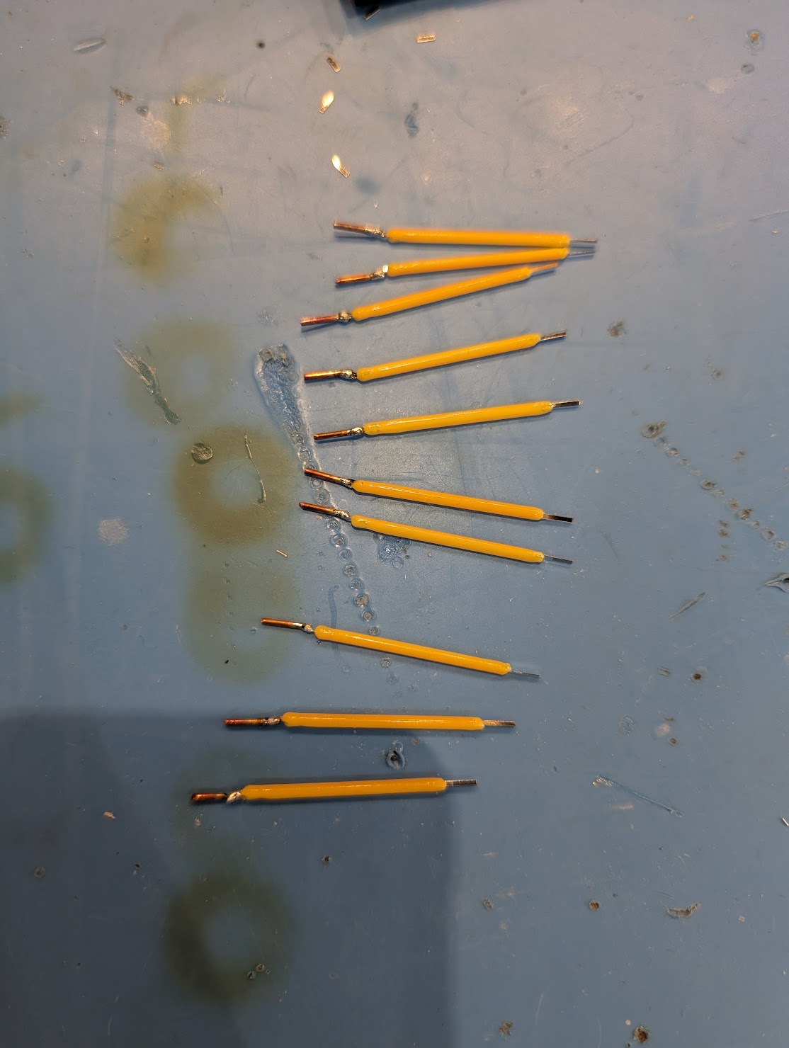
i was worried that the 3 other solder joints in close proximity would melt when i attahced the LED but I managed to do it!!!
time to repeat this 20x times until i have all LEDs attached to the bottom ring and their top spacers, then i can work on adding the battery passthrough from the top unit to get the currently assembled circuit powered. then i can work on glueing the base together and the acrylic tubes. then i just need to glue down the battery pack on the top unit and assemble the top ring to all the LEDs and glue everything together
I’ve been mulling around an idea for playing with some of these 3v filament pieces for a project for a while, and recently hatched a plan that involves running them off of a convoy 3v flashlight driver - which is a neat idea.
But I really like the looks of what you’ve got going here. Can you elaborate on what is happening in this simple circuit?
It looks like a tp4056 module wired to a capacitor, some resistors, and a mosfet - then that output being run through a stack of resistors. What’s going on here?
Thank you! Very cool work, as always.
((*I also intend to build out a lattice of copper wire and run the filament off of that. Still brain storming the shape and circuit though))
this project has been shelved until next semester unfortanutely.
the circuit right now is a BMS for a 18650 ( thats the black pcb), its output is connected to the input of the mosfet via a tilt switch and resistor ( the brass coloured canister), then the output of the mosfet goes to the resistor lattice, these are all in parralel and just arranged like this for aesthetics.
the lamp will run the LEDs well below their rated current so that its more of a decorative piece thats easy to look at than a functional lighting device. Its running them at ~10% power and they connect directly to the battery pack via the resistors and mosfet.
the entire device is made from clear lasercut acrylic and is hexaginal shaped. its meant to only have one input/output which is the USBc for charging only. otherwise the tilt switch turns it on or off.
if i were to restart i would make a hidden section with a microcontroller to pwm the LEDs and a accelerometer as the tilt switch and use either a capacitive touch sensor or maybe a hall effect sensor to do some method of setting the brightness. it would really simplify everything and let me do normal wiring that i can easily hid instead of having to carefully manage the bare copper
1 Thank