4/27
Still not sure how I want to do the rest of the head but it begins with the pill and the connection between the head and the tube. To make this connection I’ll use a 1/2” compression union soldering 1 cap to the head and one to the body with the driver and led going into the union(or some part of it).
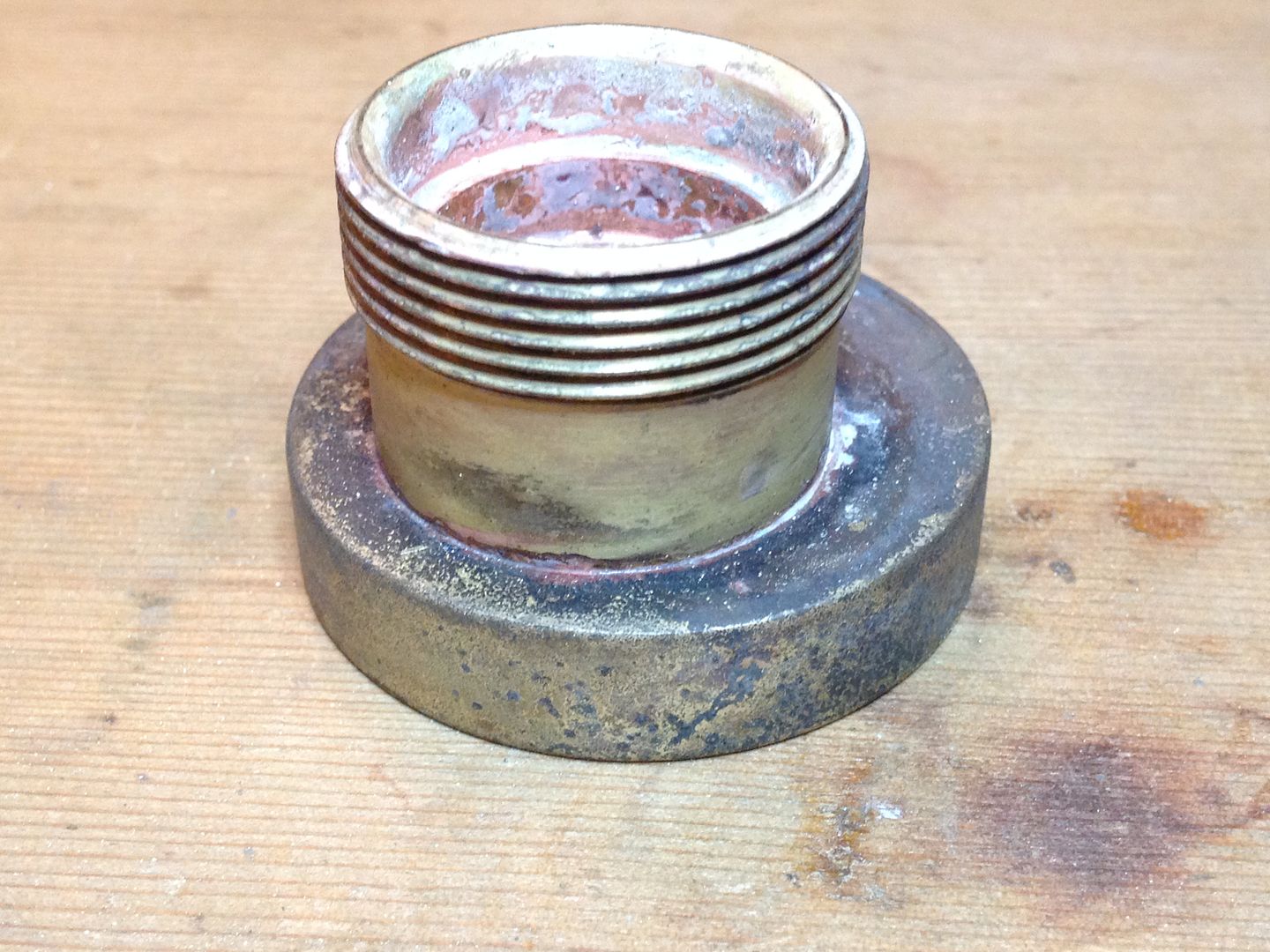
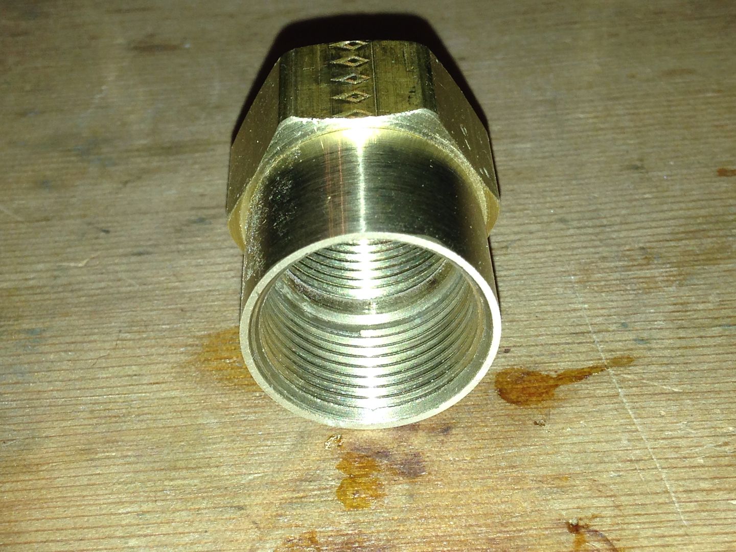
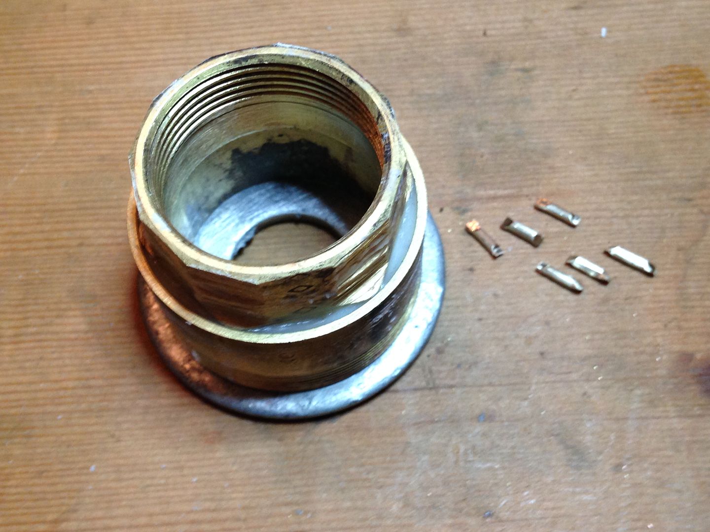
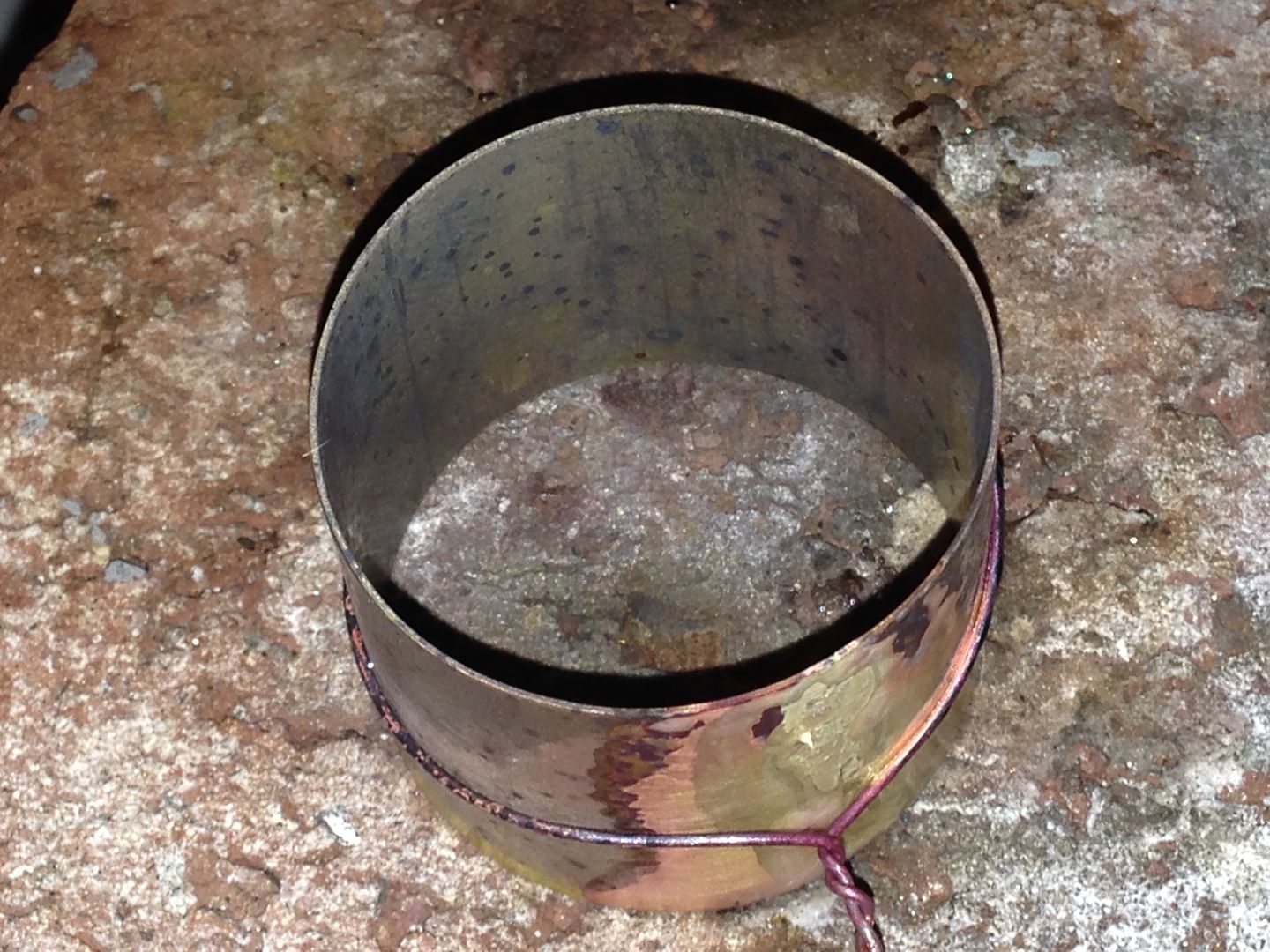
As is a 1/2” copper pipe fits this but it’s heavy and the wall thickness is ~2.4 mm. Also, there is a pipe stop in the middle so I’m going to ream it out so that coupler fits instead.
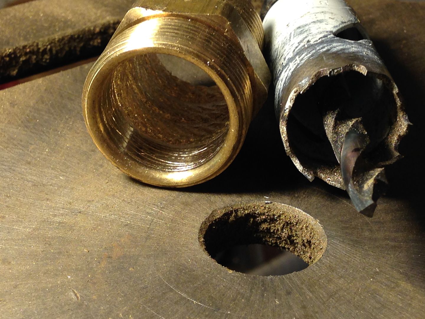
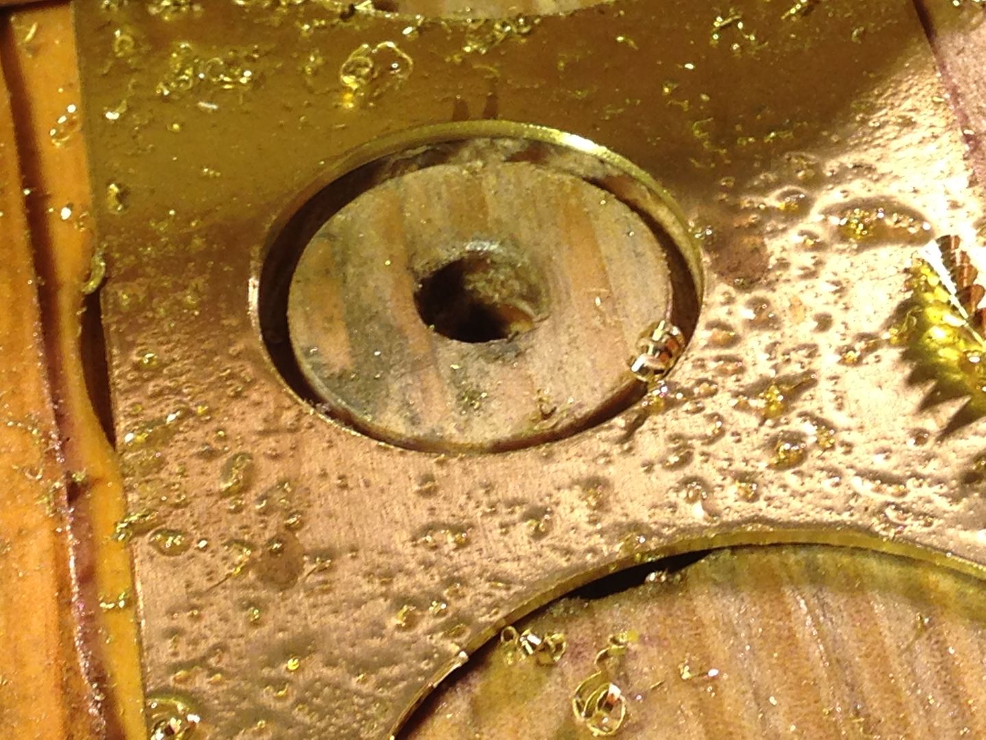
I quickly bored this out with a hole saw.
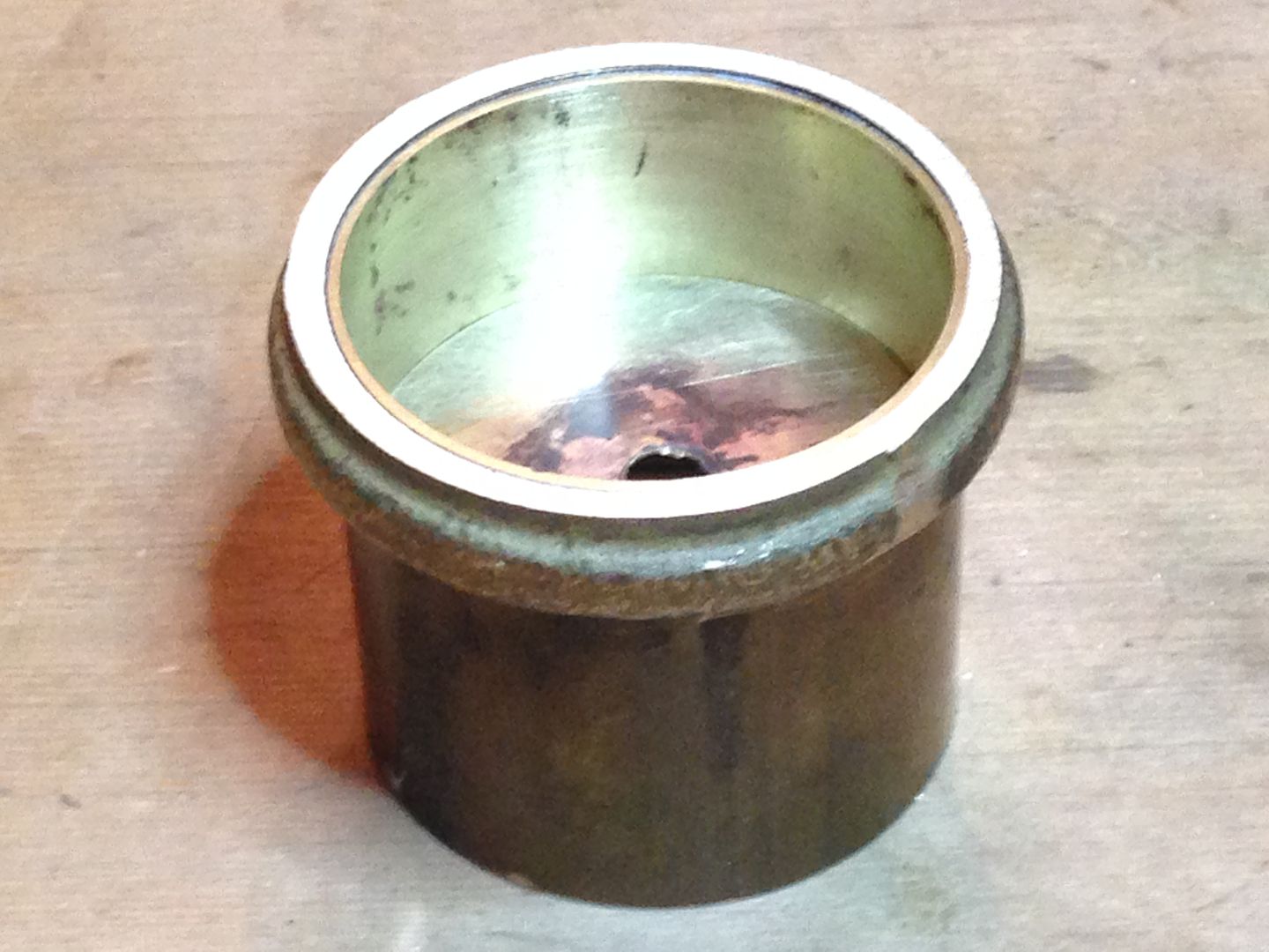
Ugly, I know, but after spending 3 hours reaming it out with 200w/d wrapped around a 1/2” bolt chucked into a hand drill it looked much better. The last few passes where lubricated with water.
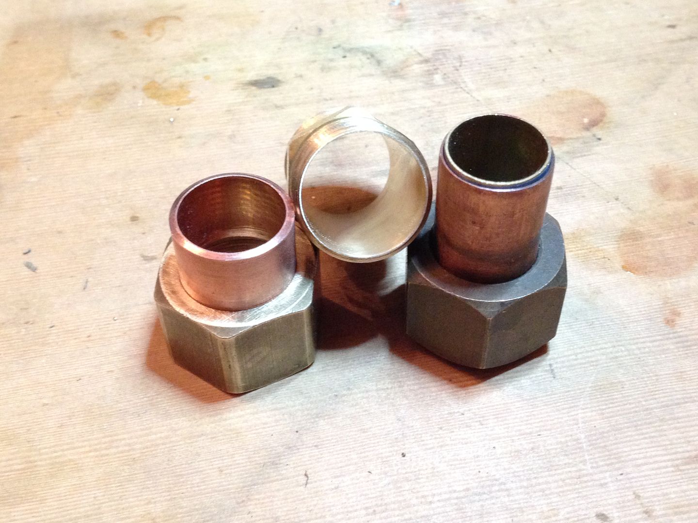
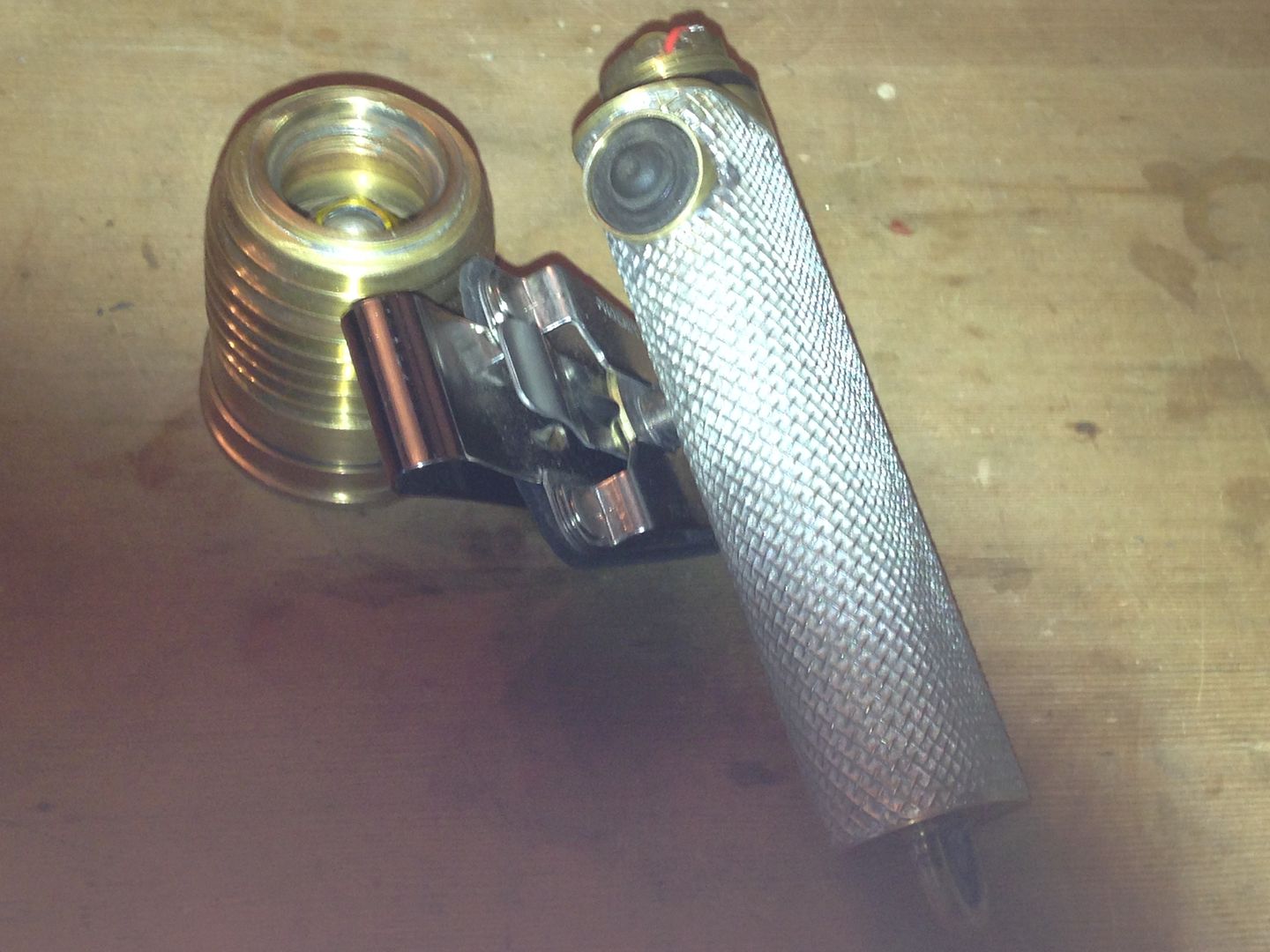
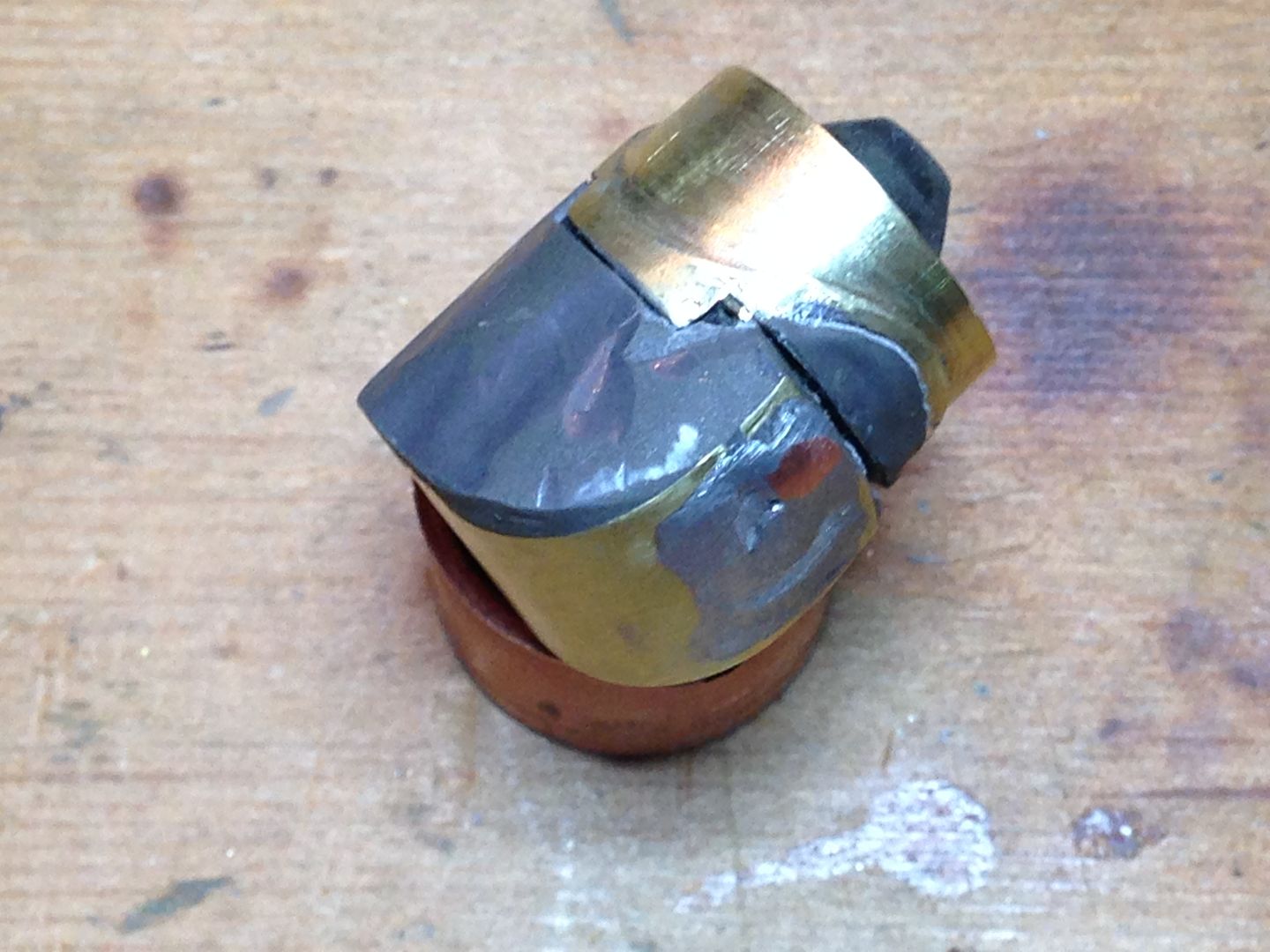
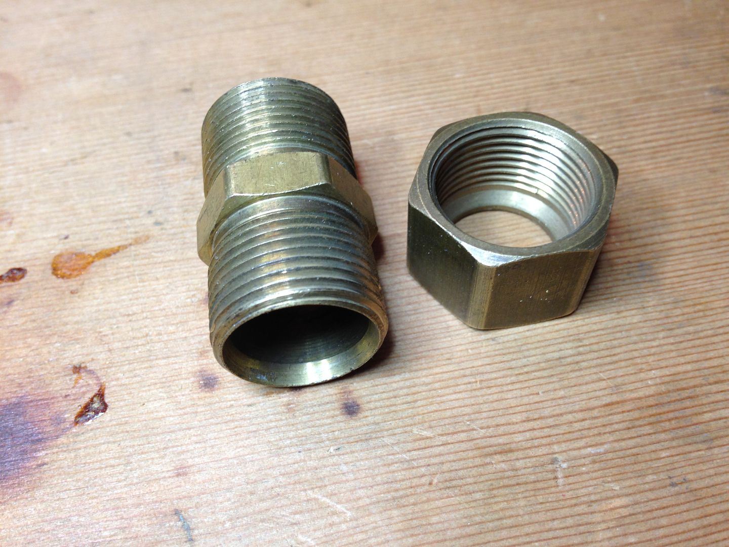
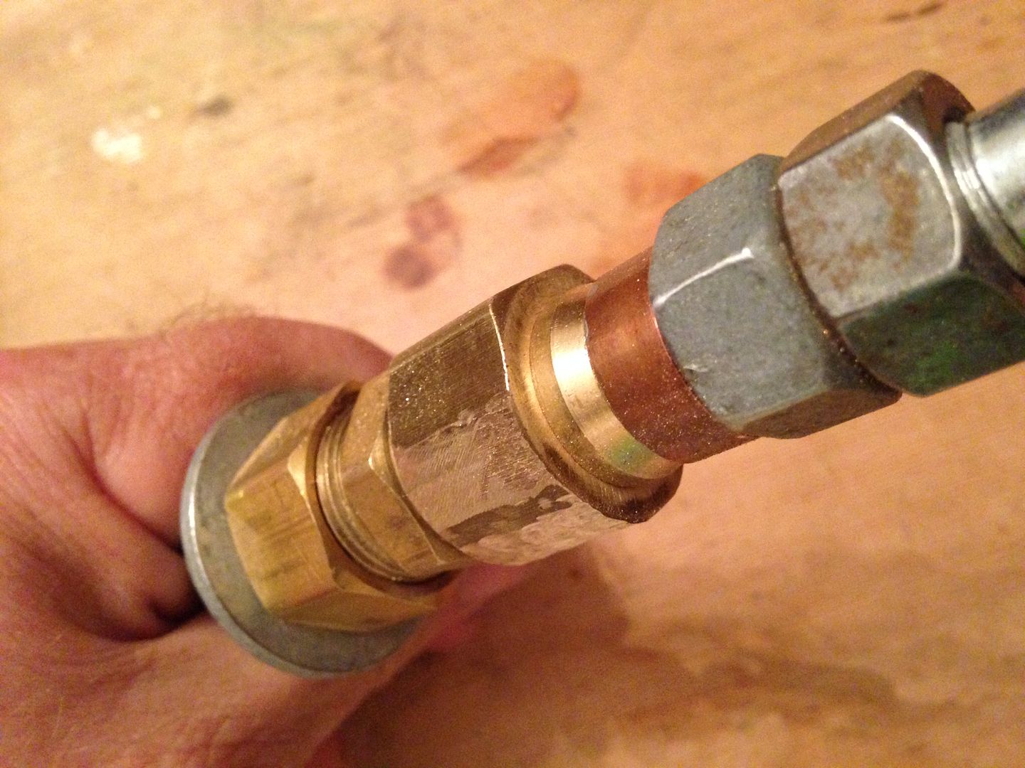
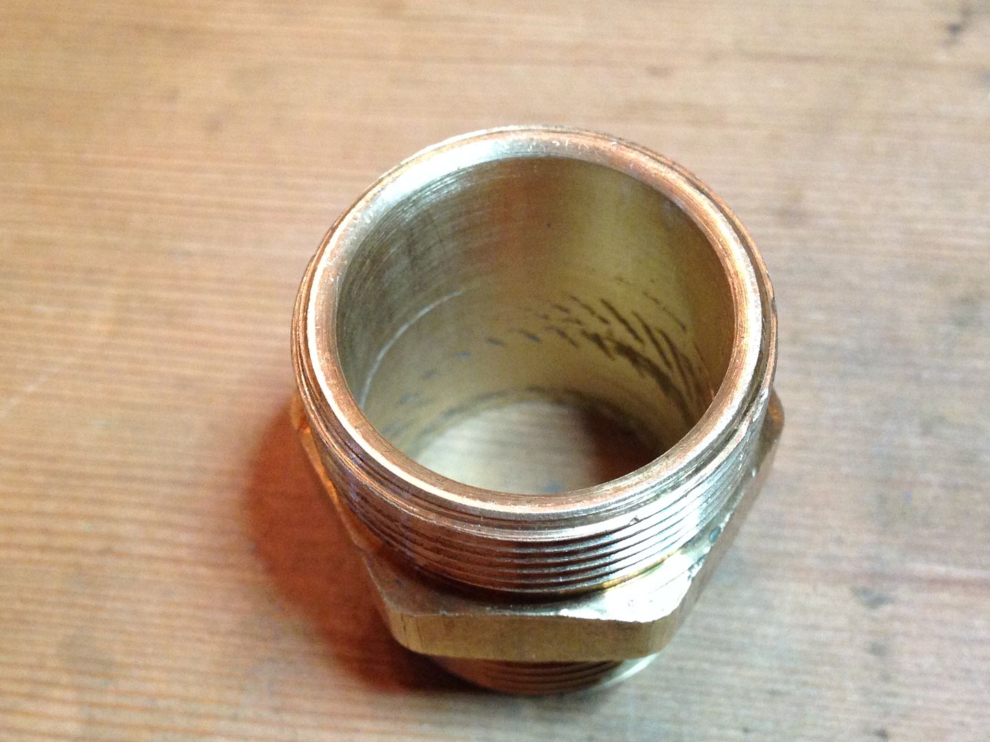
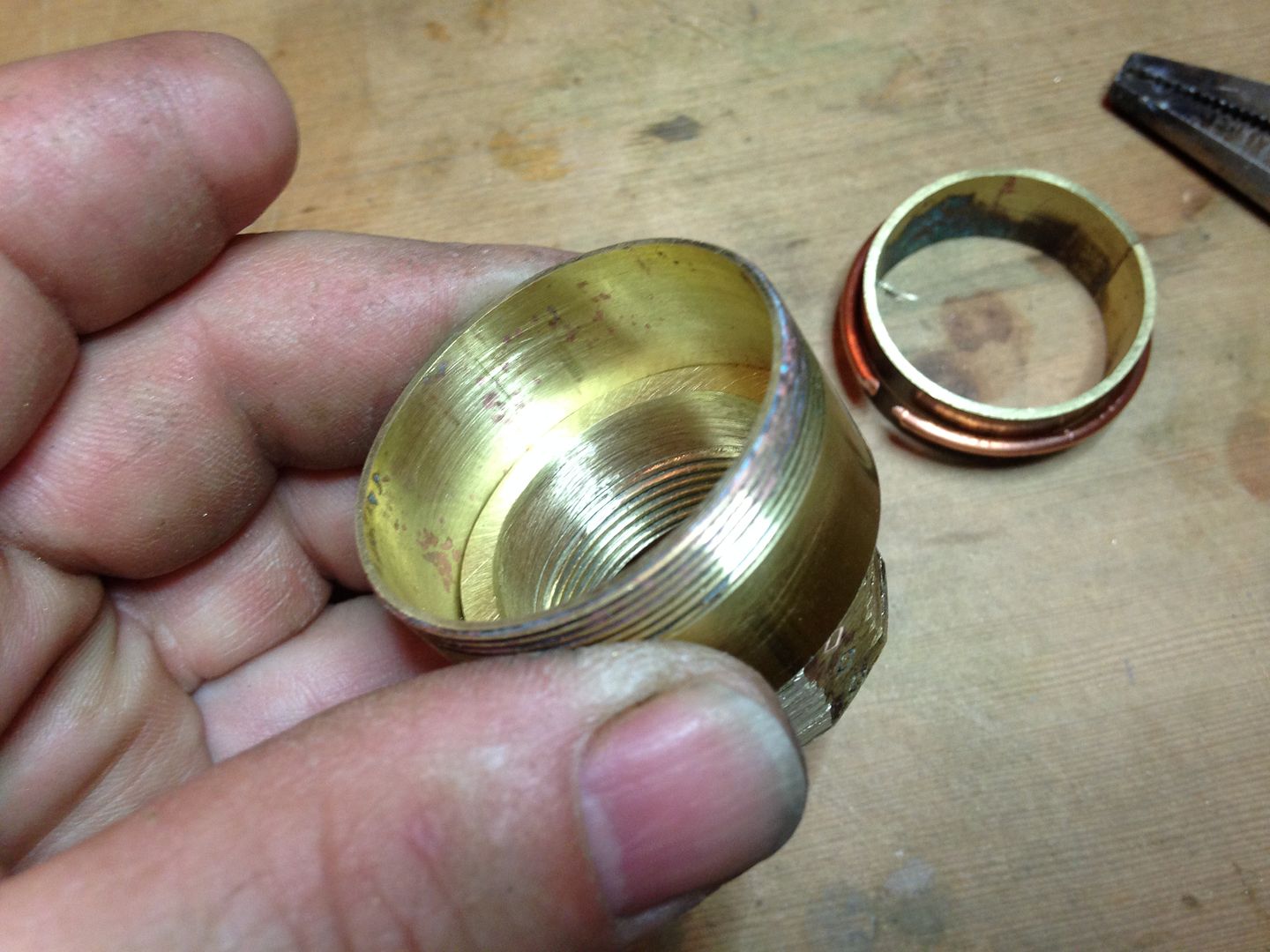
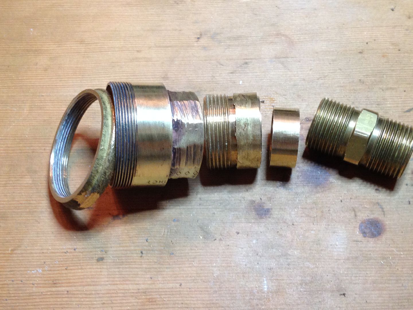
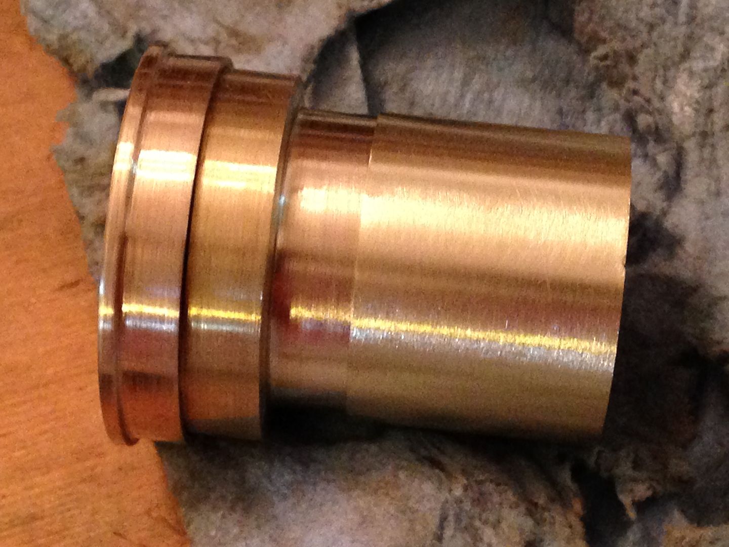
The cap on the right is stock and union and cap on the left now fit the coupler dimension. Wall thickness of the union has been reduced by ~1mm and the coupler is now a better fit than the pipe was.
5/1
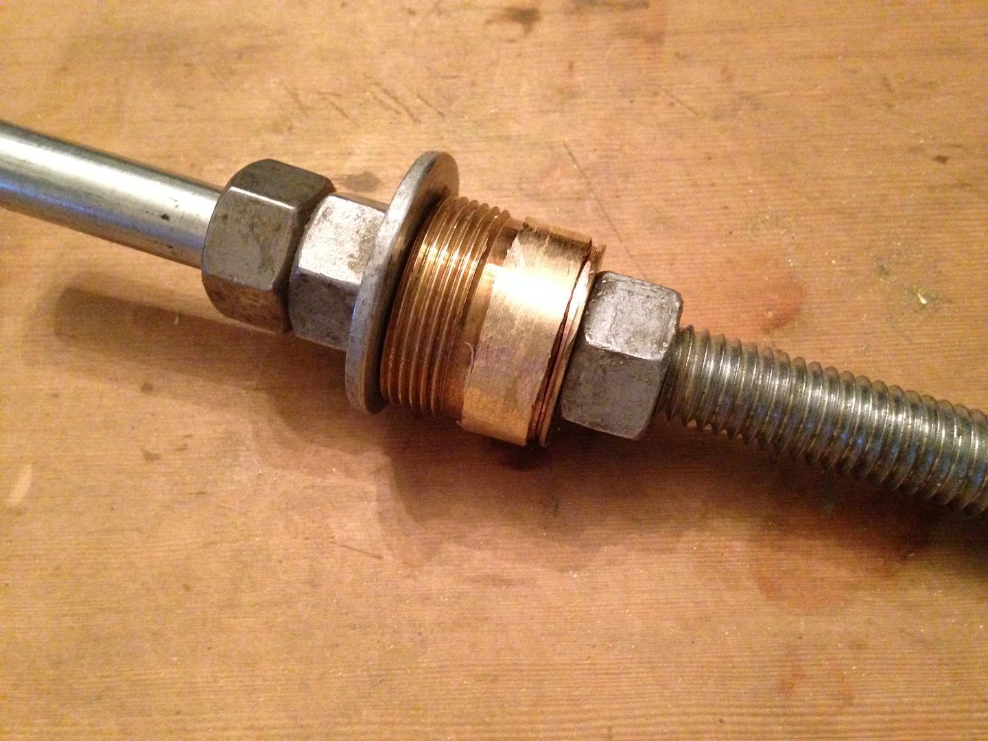
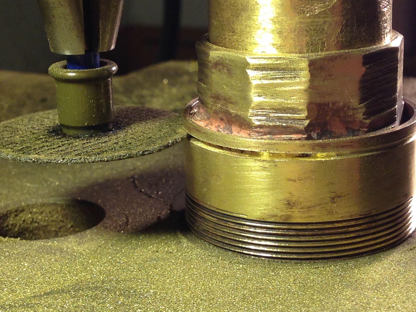
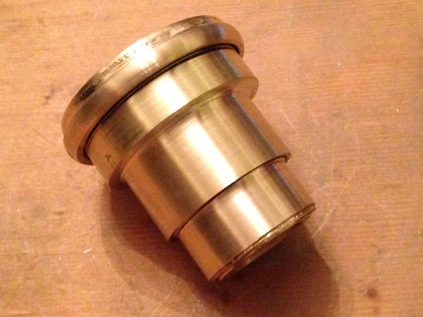
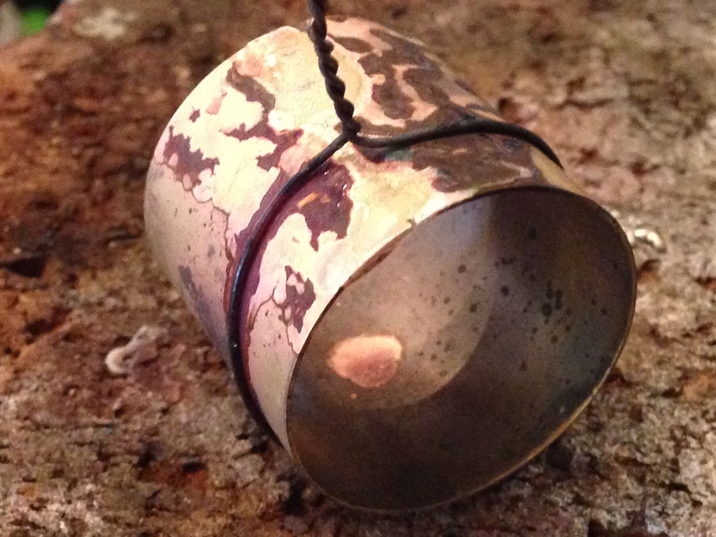
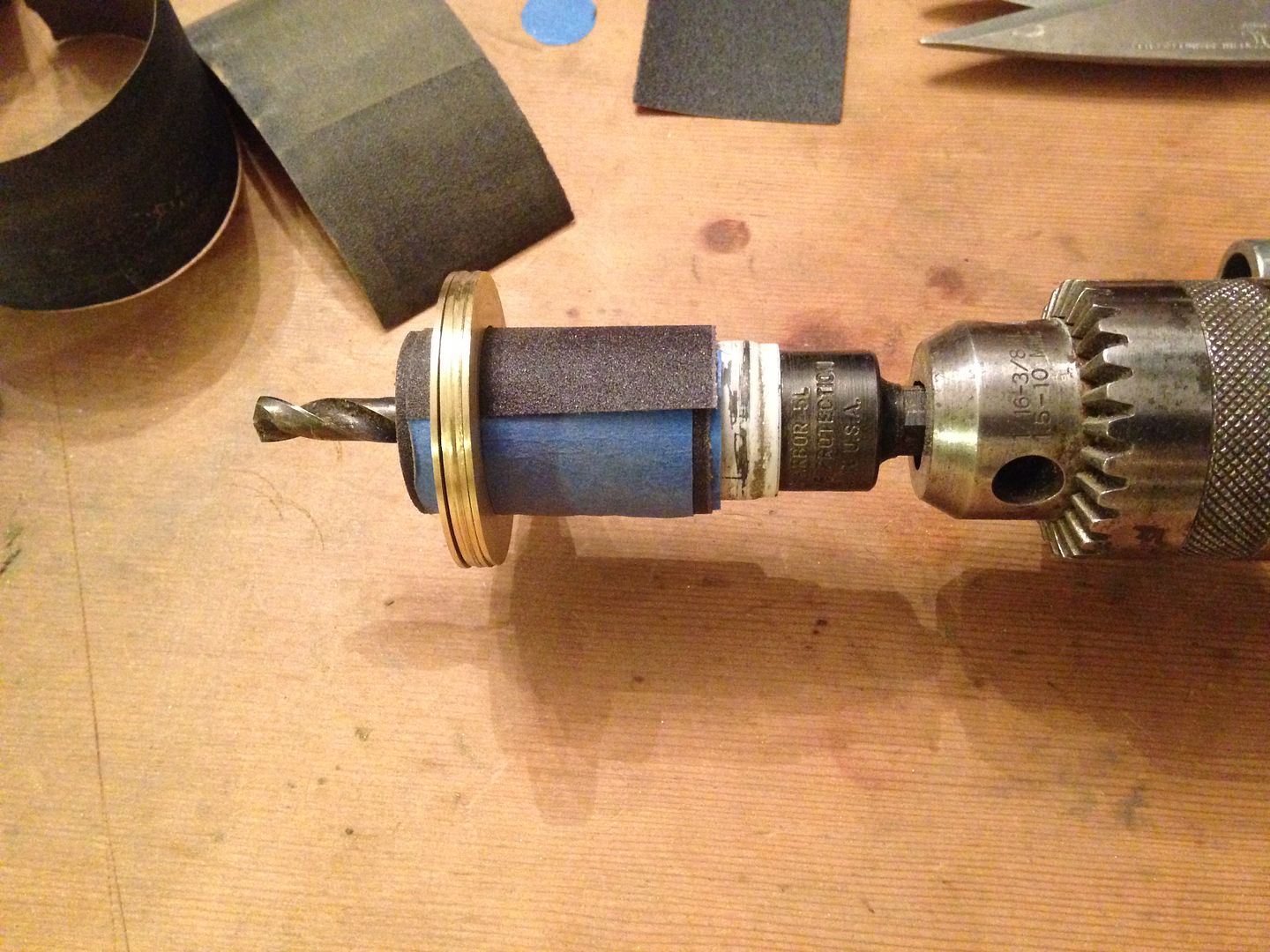
More grinding. With the same bolt I used to ream out the inside of the union I cobbled together a means to turn down the outside of one of the union caps. Here it is with most of the corners already ground off with the Dremel.
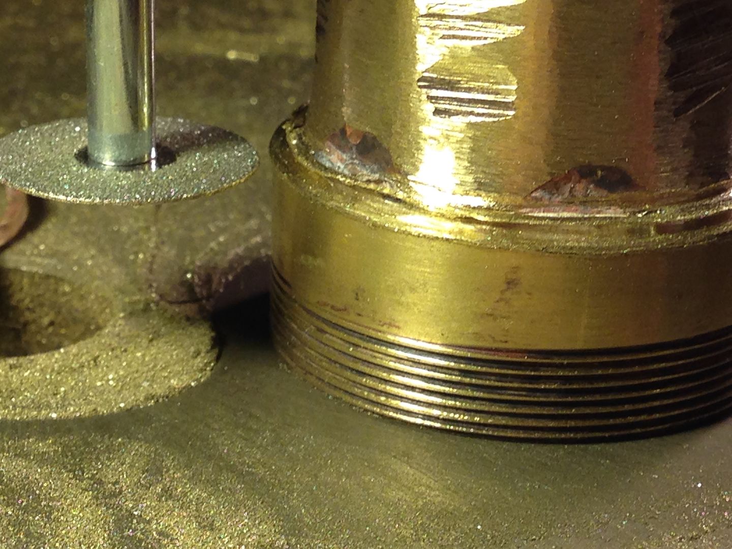
Then I put this thingamajig into the drill press and started spinning it down with 200 w/d.
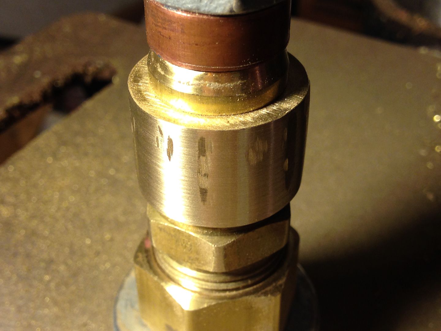
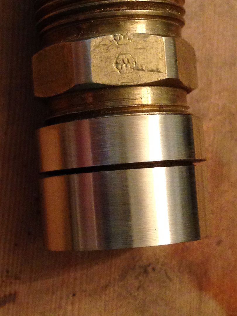
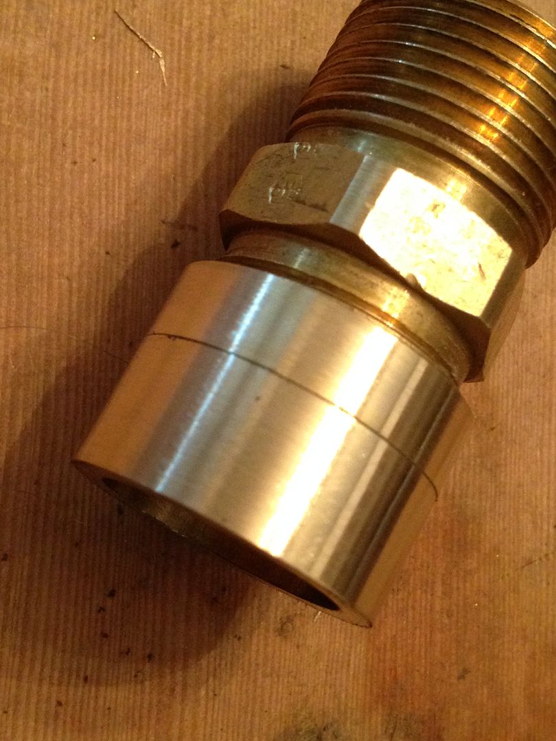
I kept on with this until all the flats and tool marks were gone.
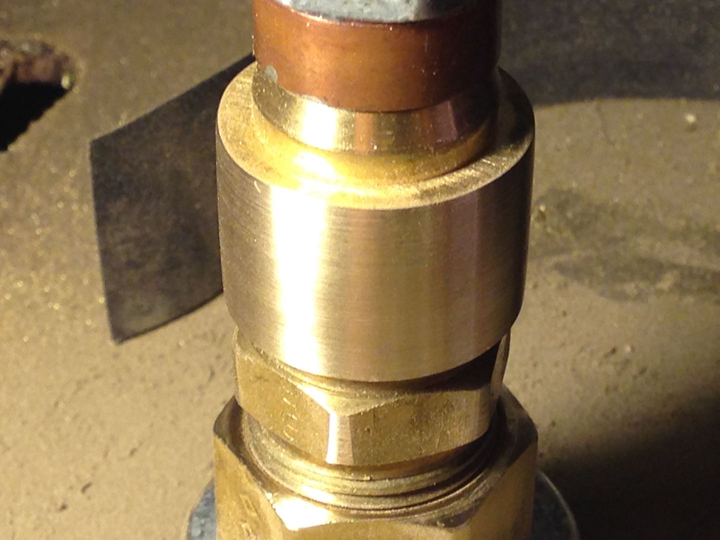
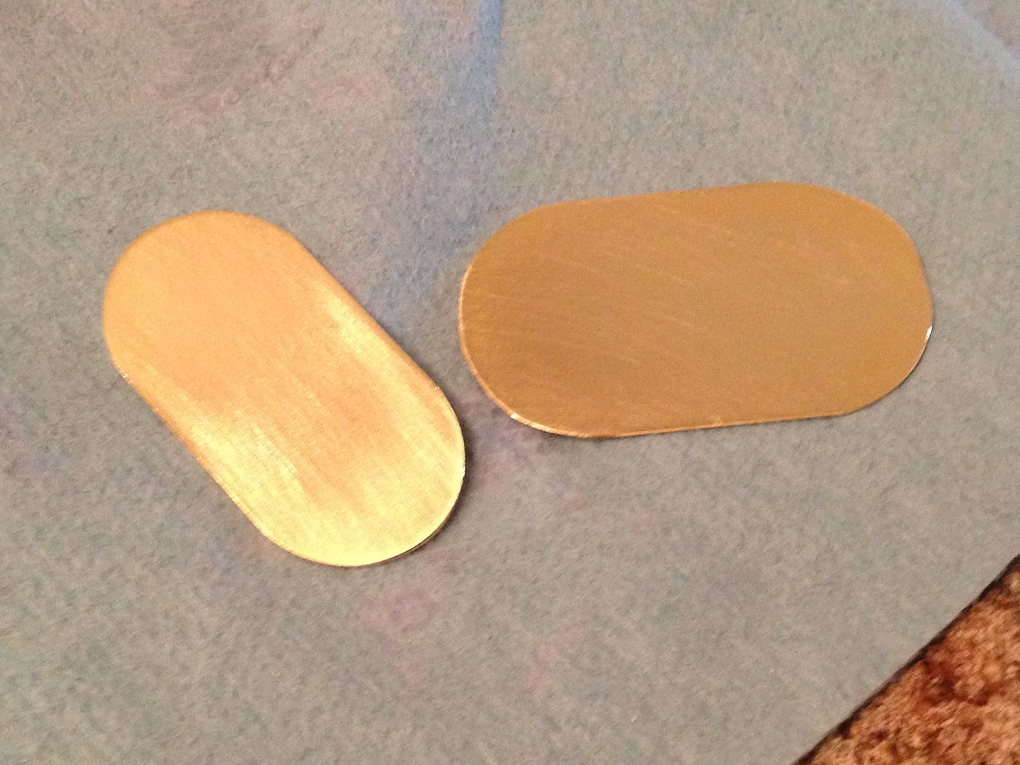
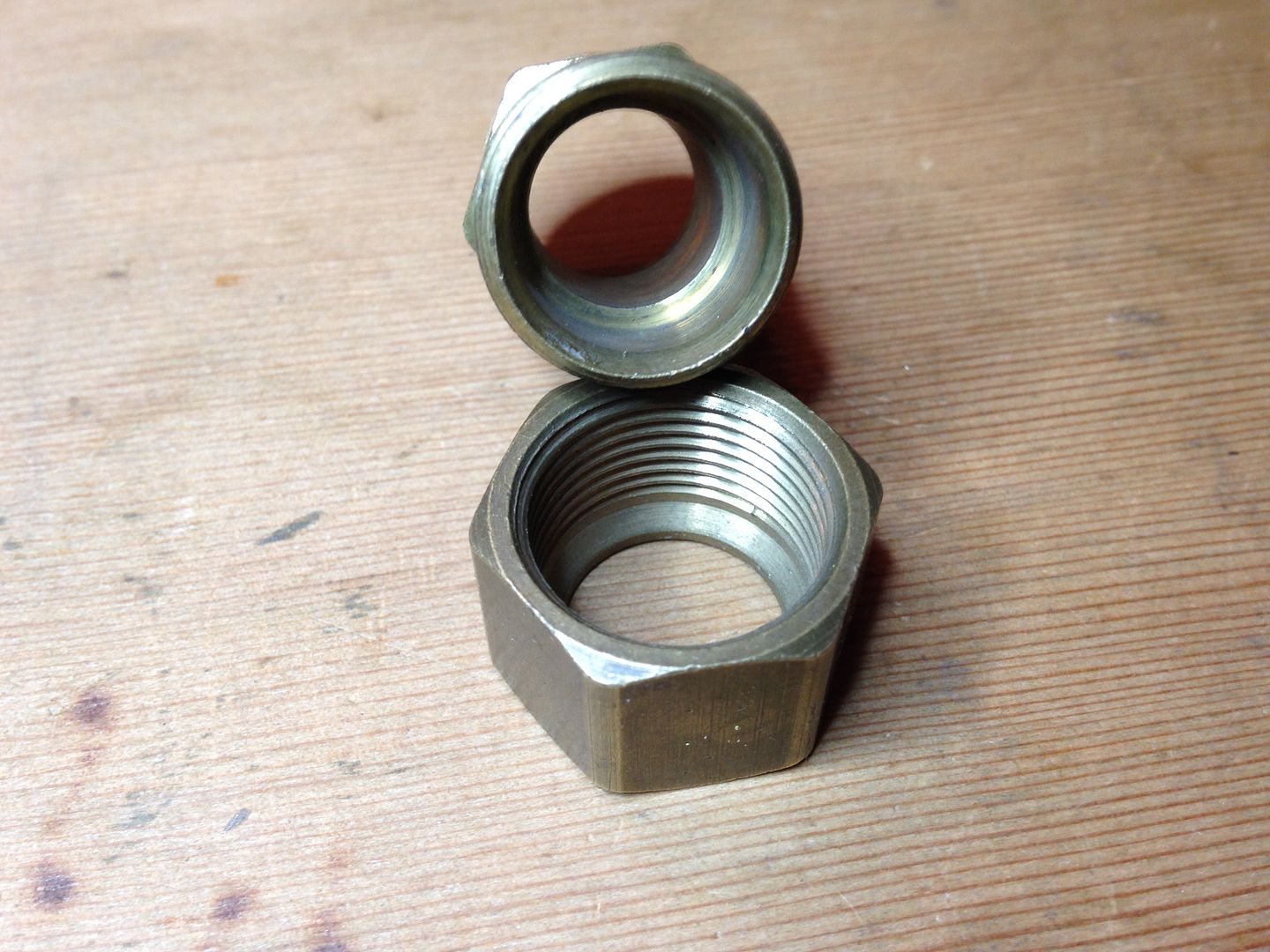
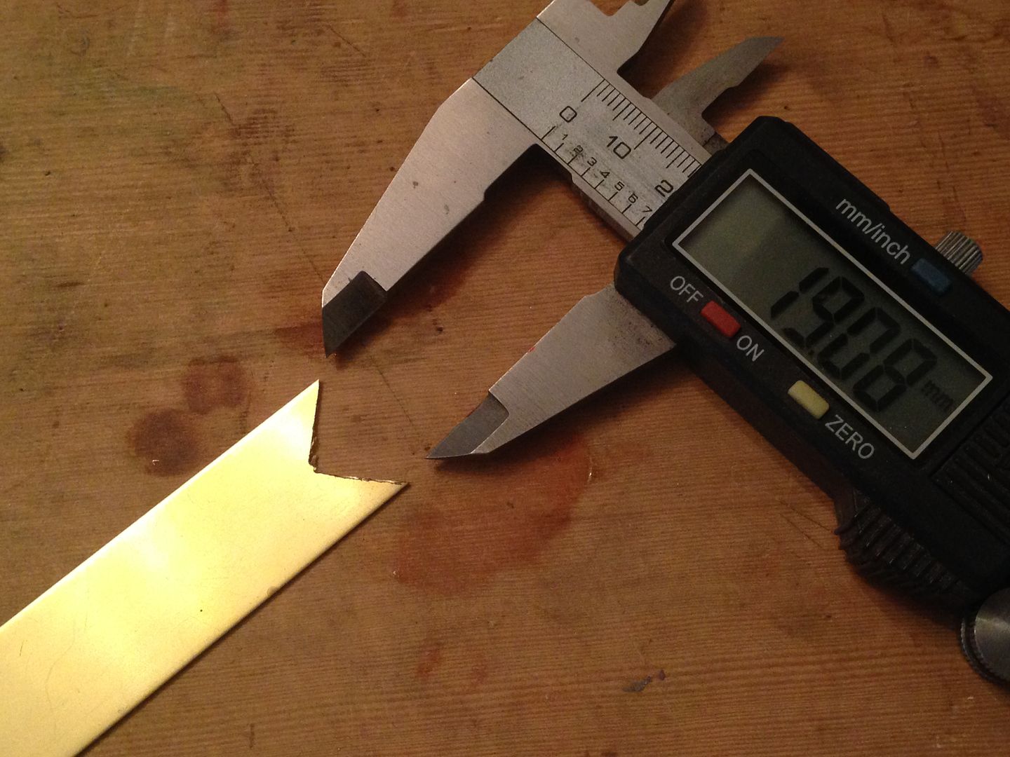
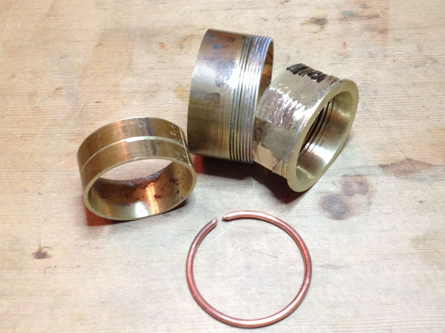
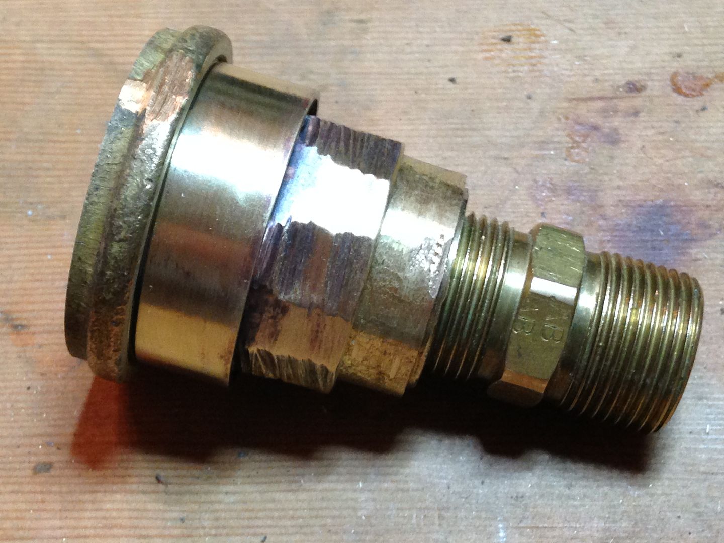
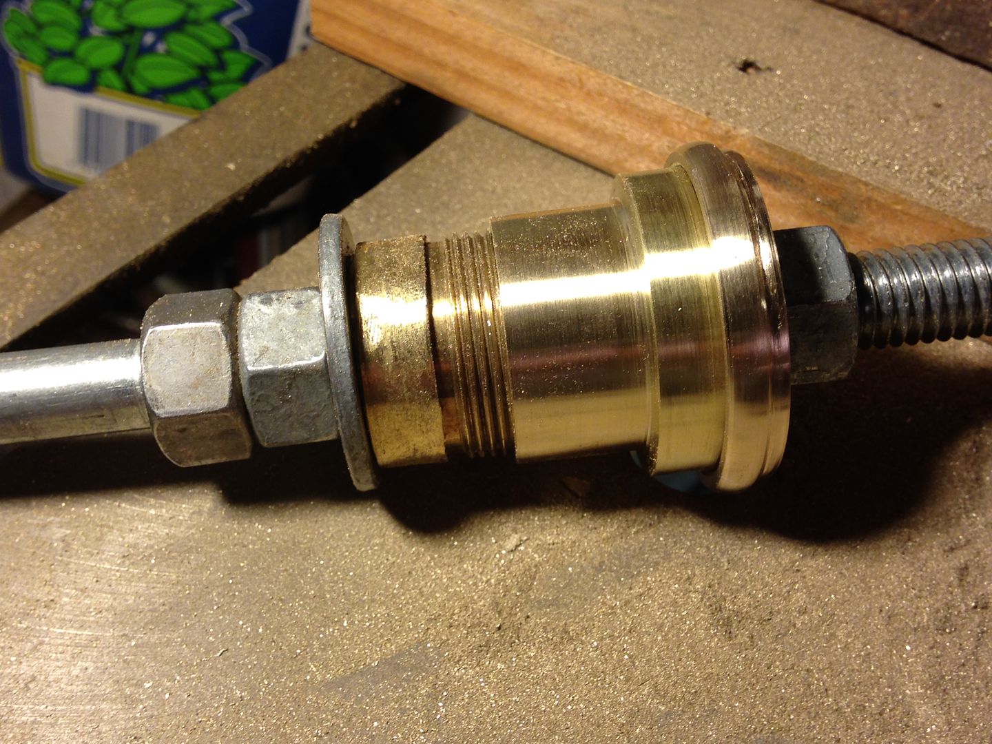
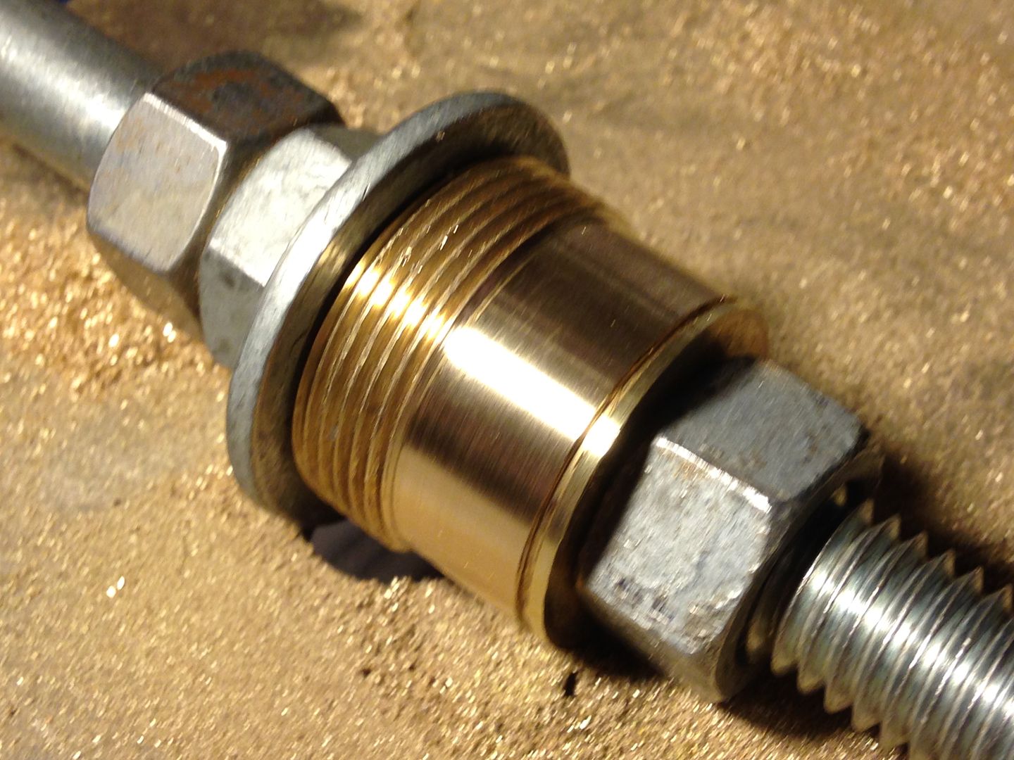
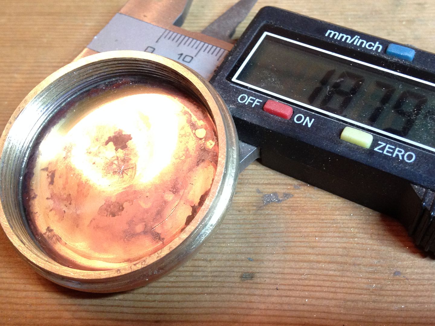
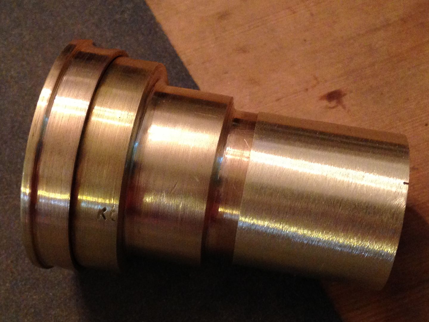
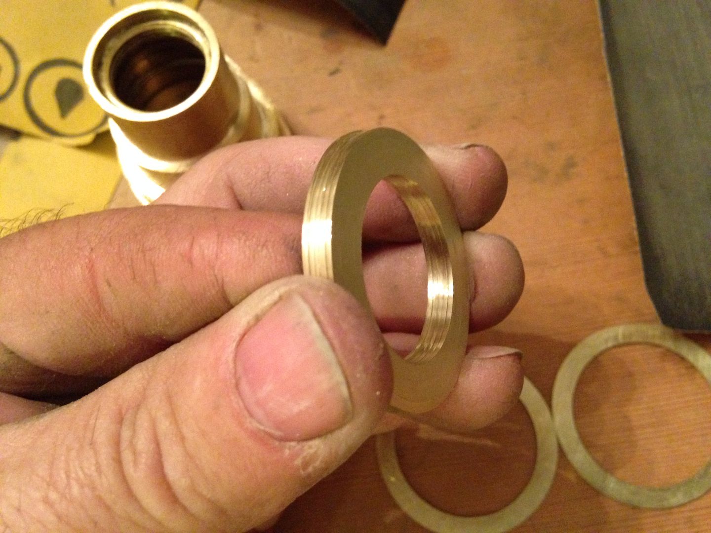
At this point I removed it from the jig to check wall thickness and find out what I wanted for a final OD. It measured 23.9 mm so I decided to stop around 23mm. I rechucked it and sanded some more, sometimes with a strip of paper backed by a file, sometimes backed with a finger, and finishing with single passes with the file to true it up. Here it is end to end with another cap showing how much was removed.
Short stint in the shop and other chores to do now. Hopefully more this weekend.
05/02
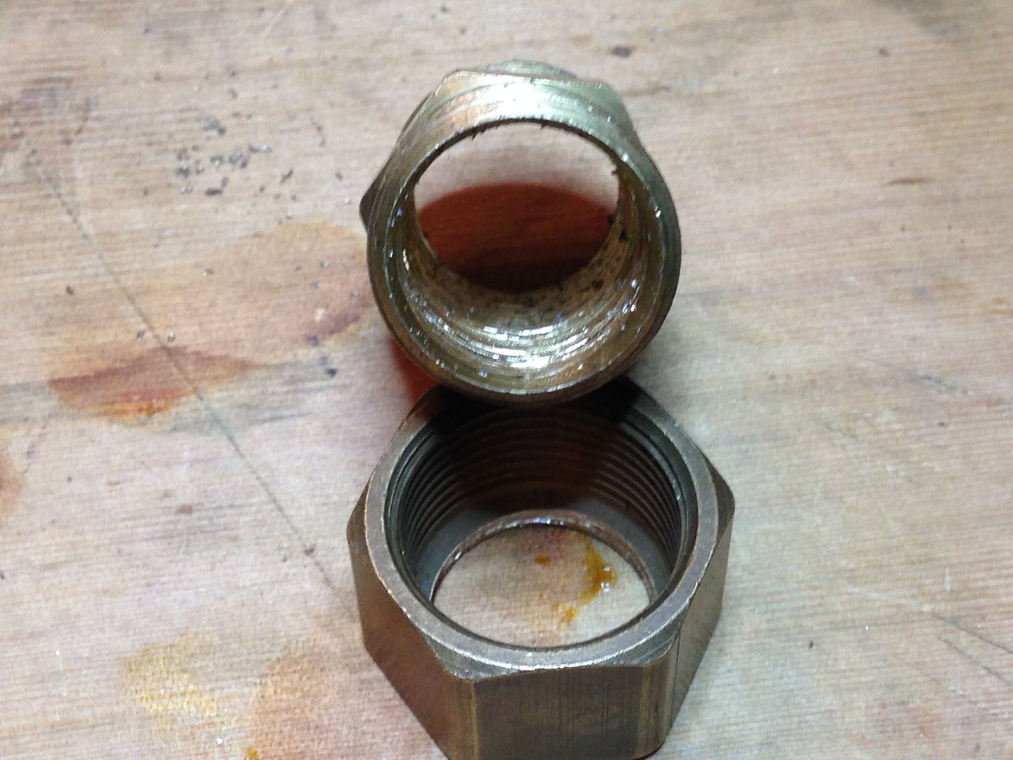
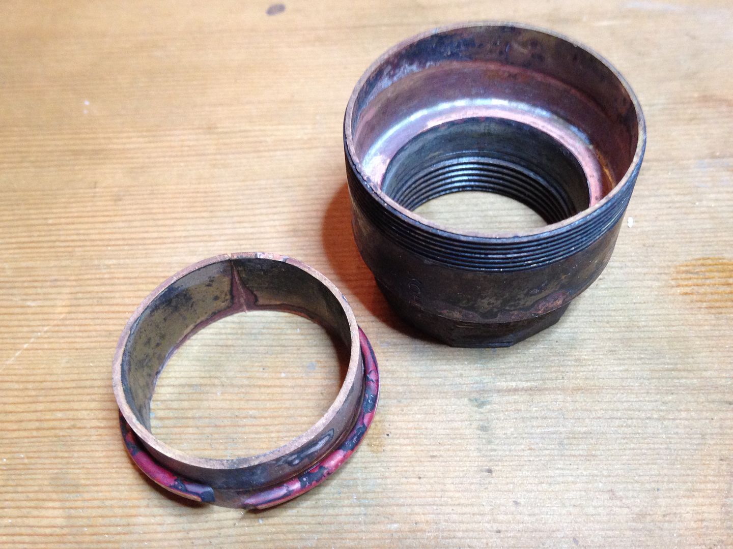
I crammed in a bit more. Cut the cap with a diamond Dremel blade (makes a very thin cut and lasts awhile).
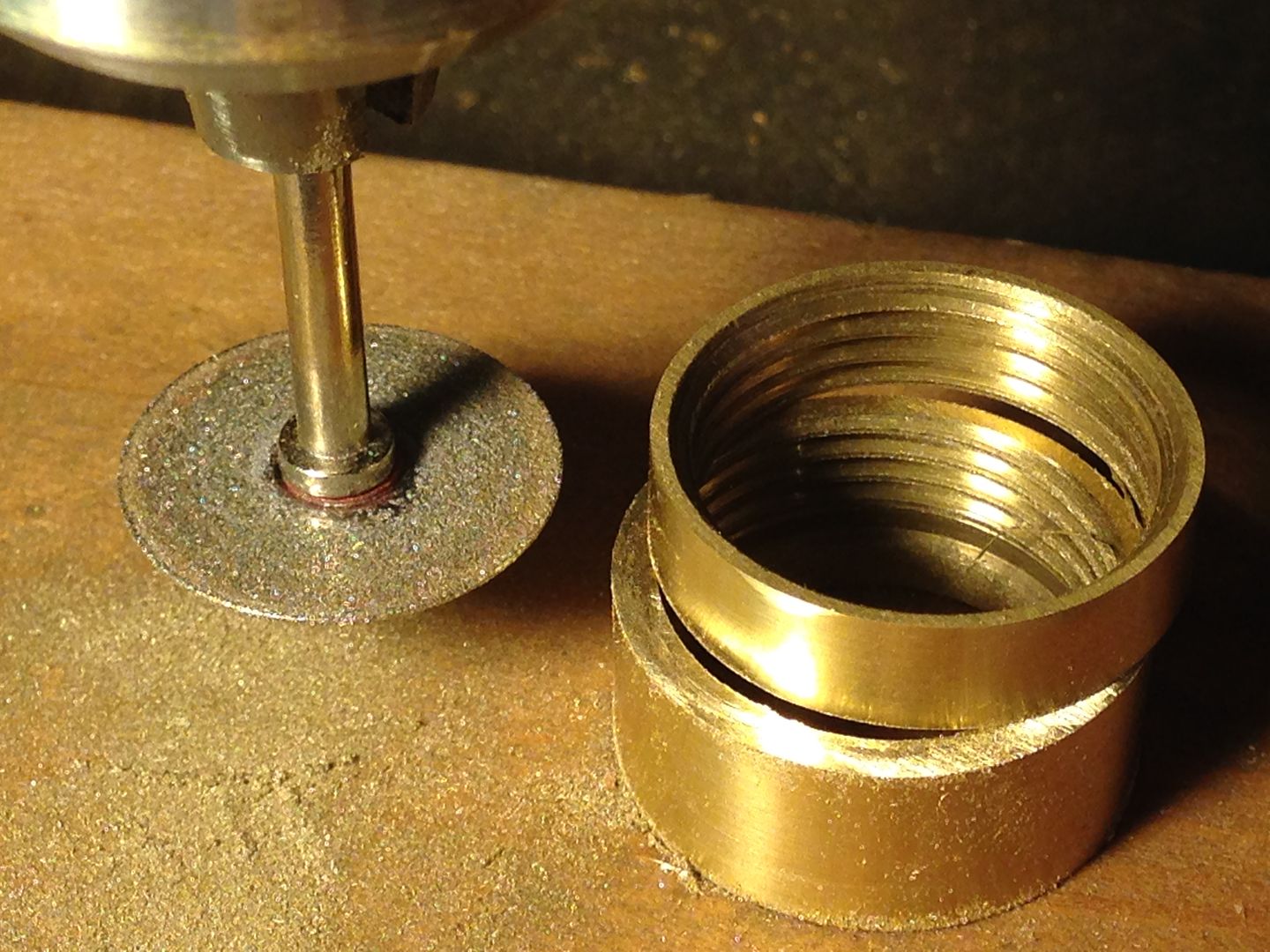
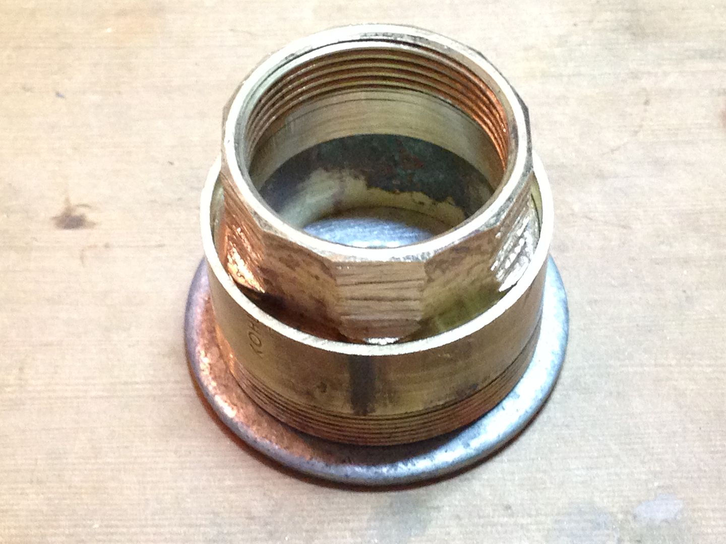
And here are the two pieces back on the other part which will become the pill(2 pills , actually).
05/04
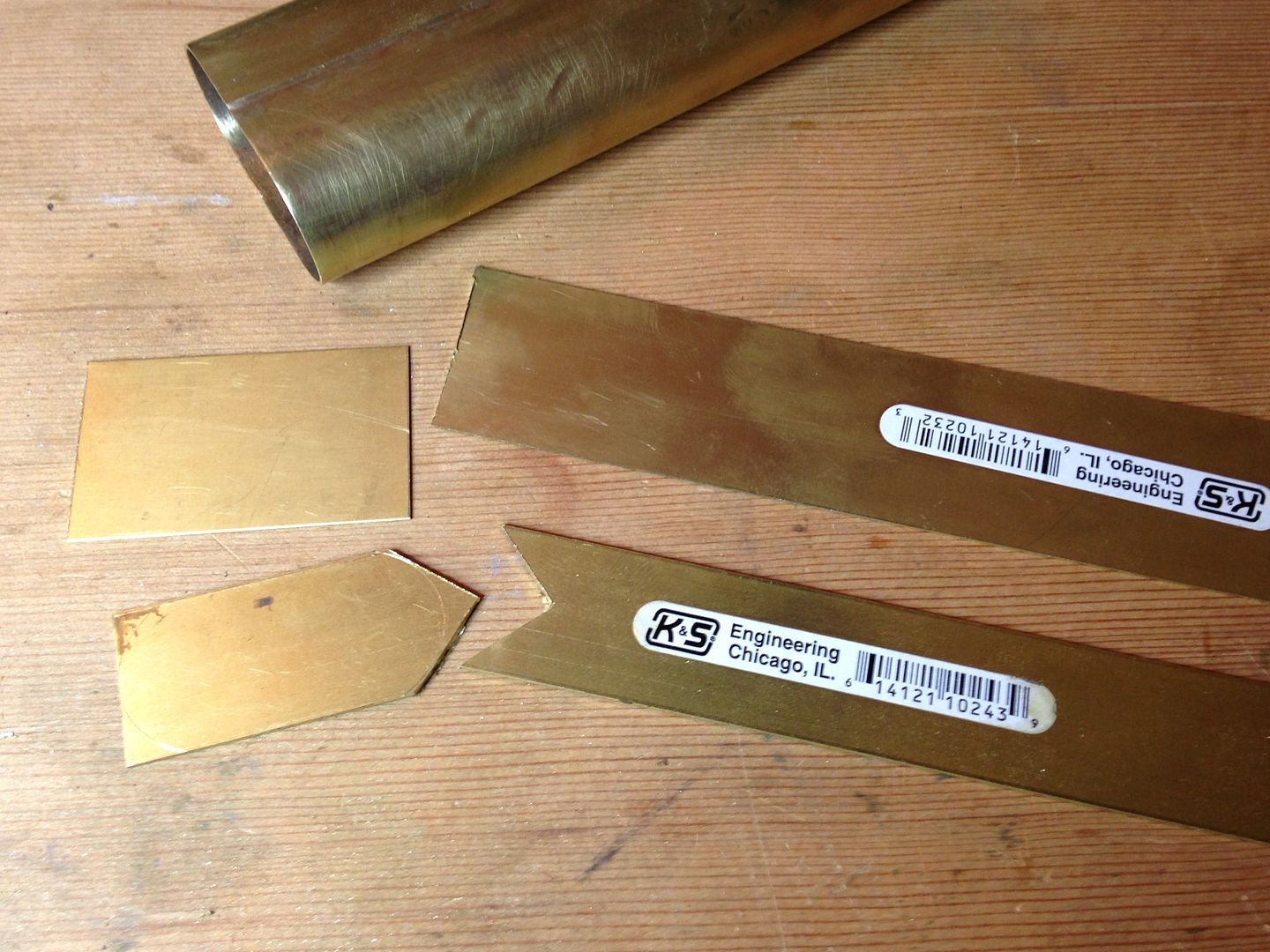
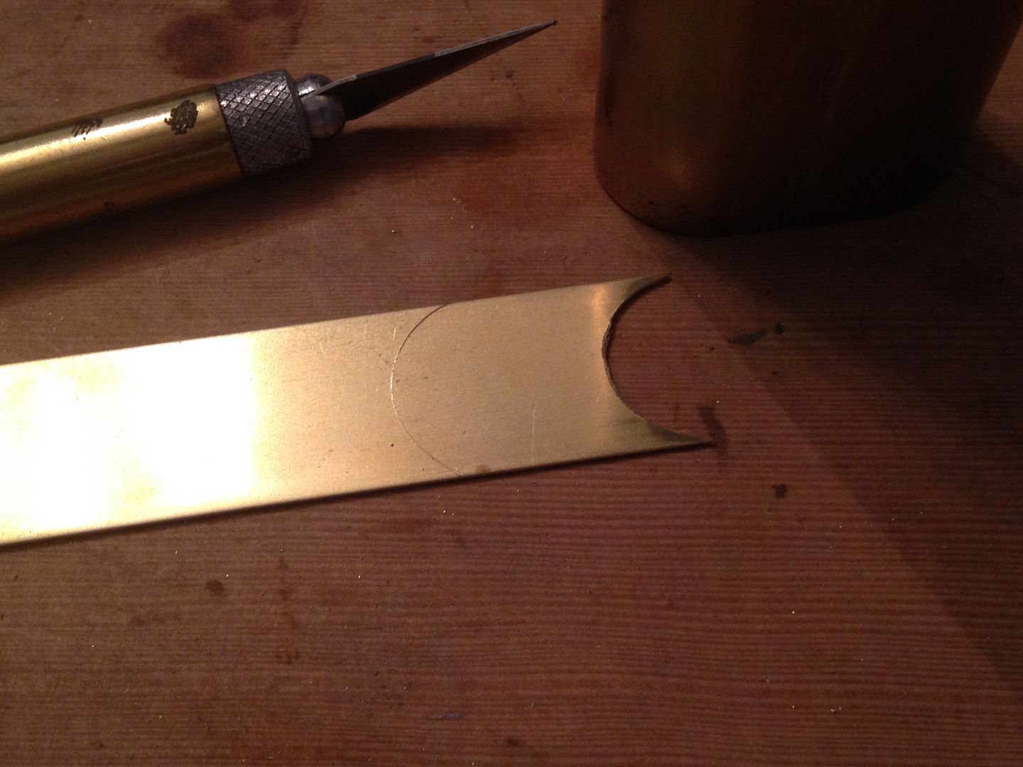
This part covers how the top gets put together. It will be like the bottom plate with a locater/backing plate but is complicated by the threaded hole for the batteries and pill. I started with this piece.
Then roughed out where the hole will be and scribed the cut for the other end.
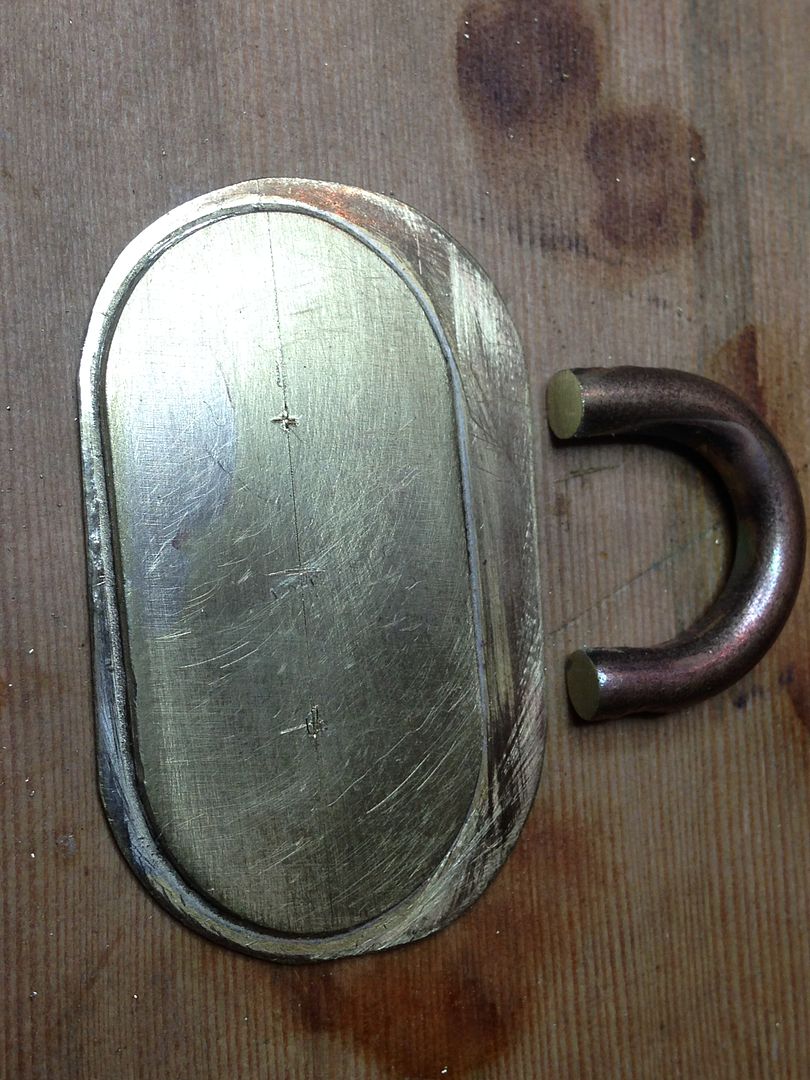
Since there will be multiple brazing operations and I can’t afford for this piece to float like the other end I drilled it for 2 brass pegs. I drilled the inner plate first then clamped both layers in the vise and finished through both.
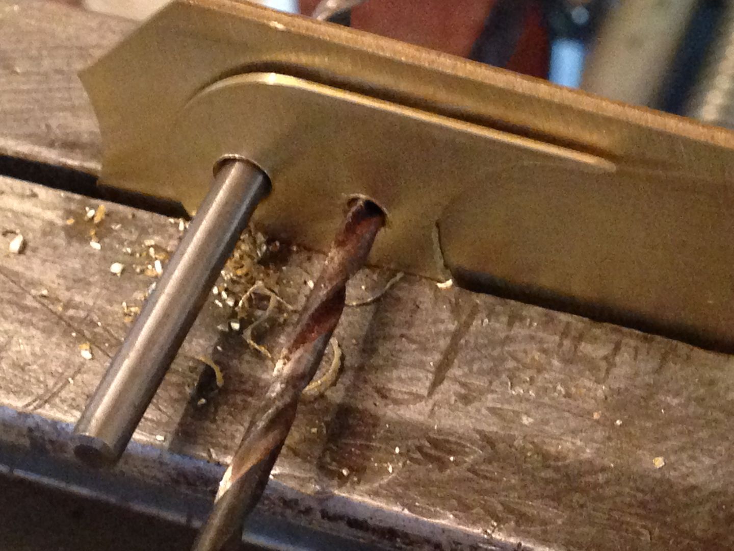
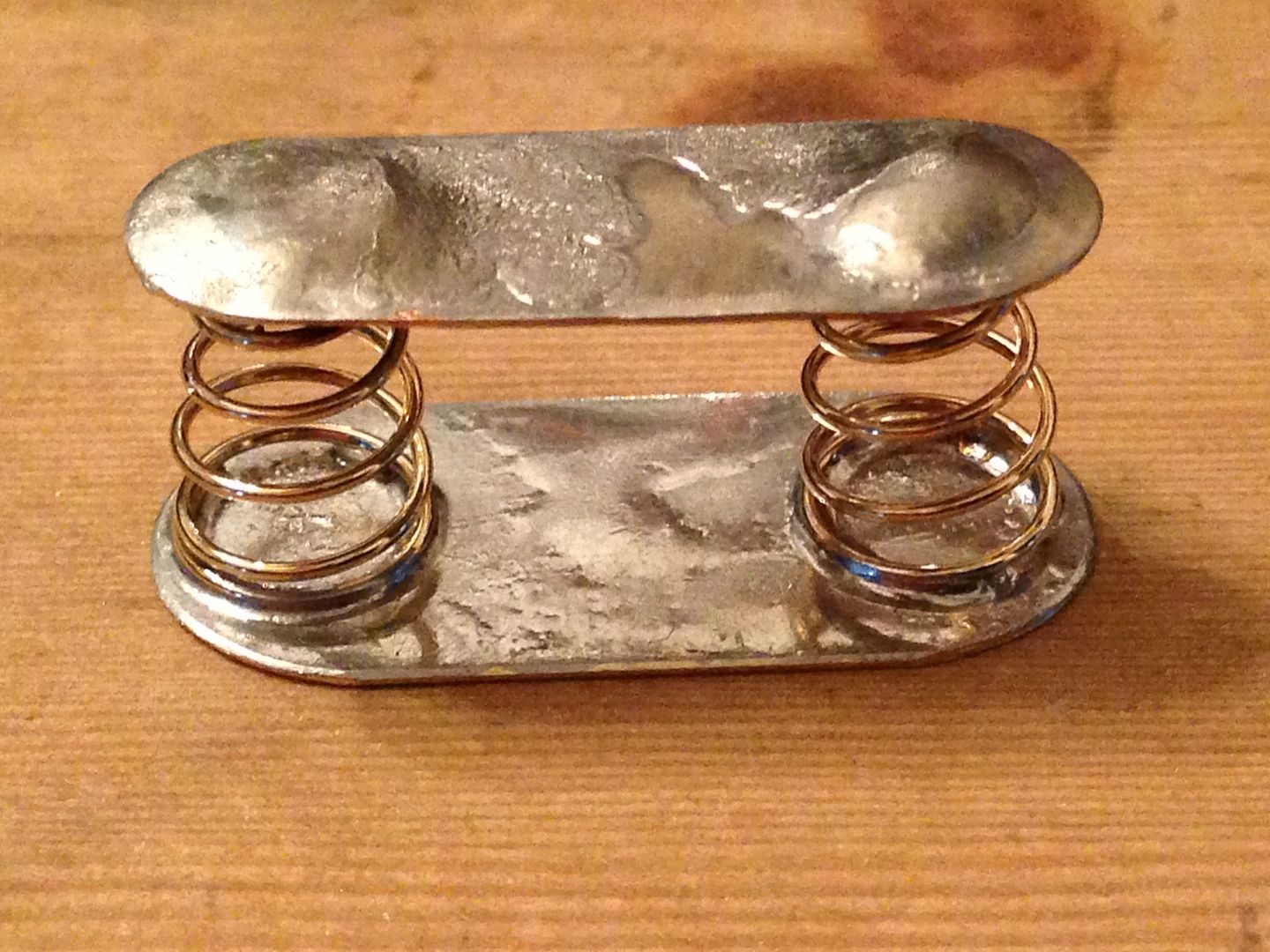
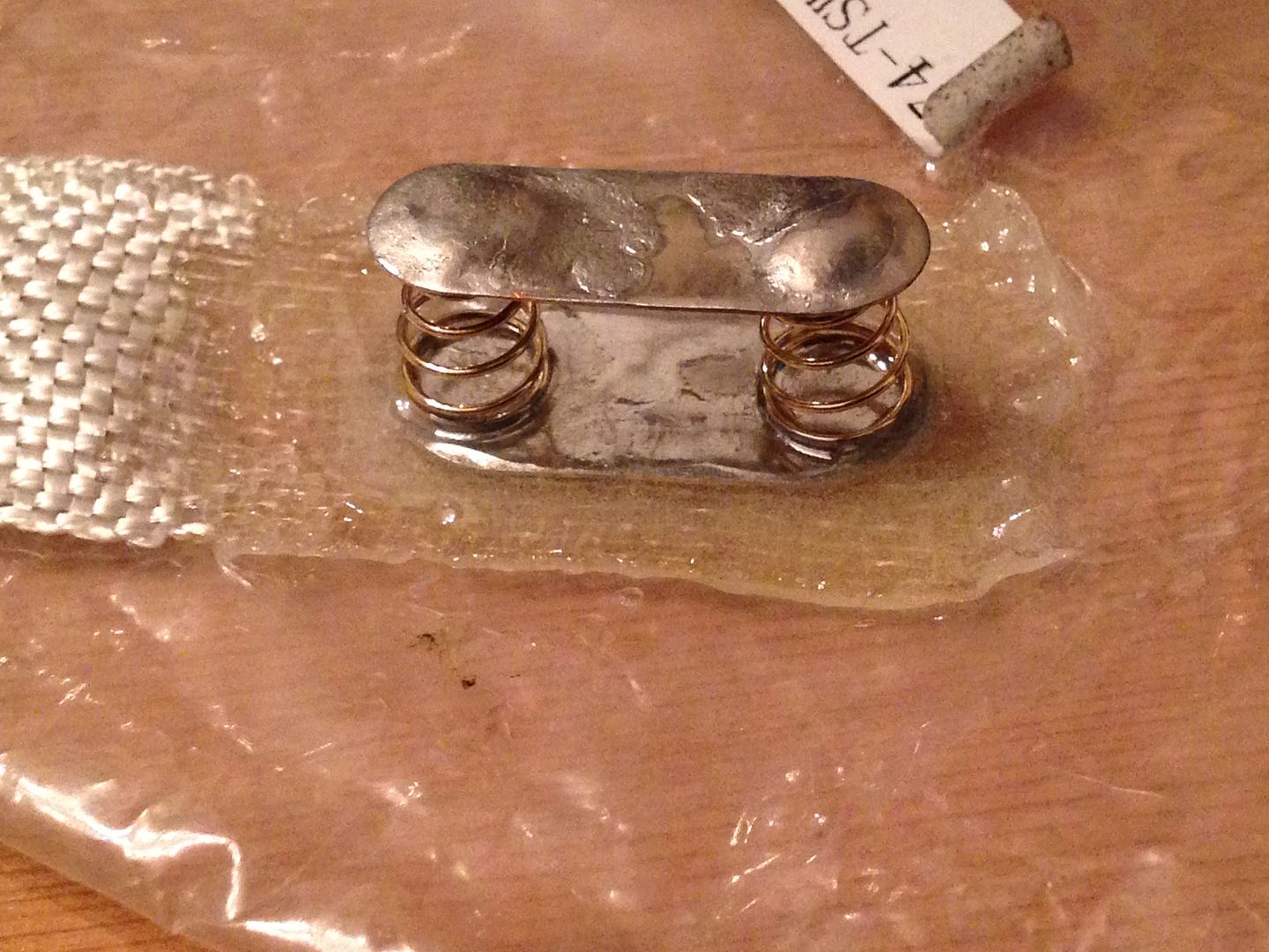
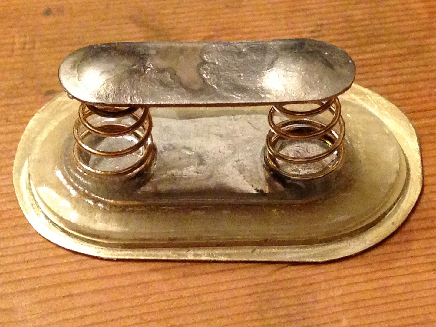
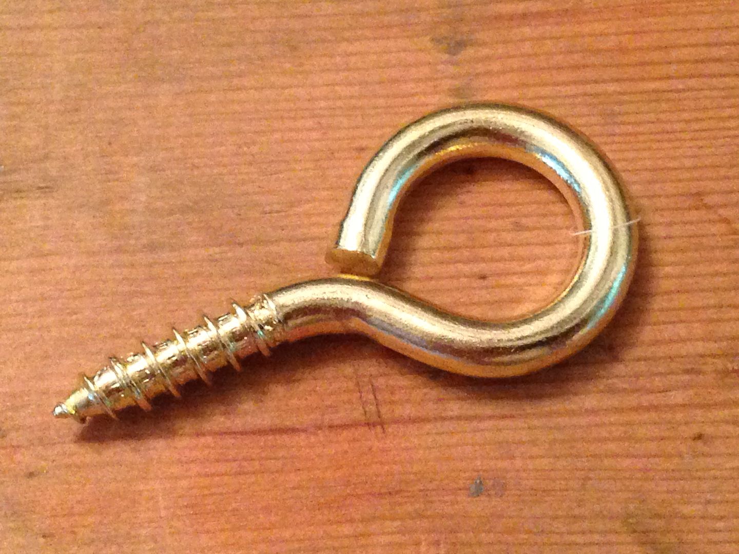
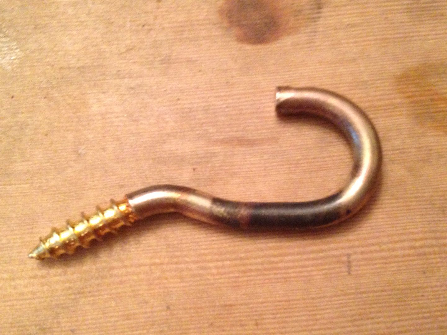
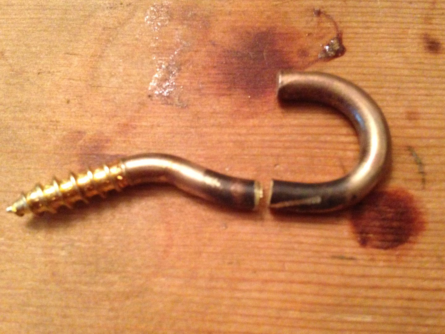
The “pegs” were cut from a brass screw eye I will use for the lanyard ring on the bottom.
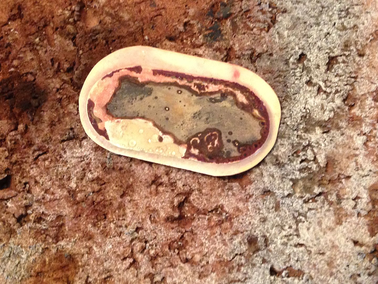
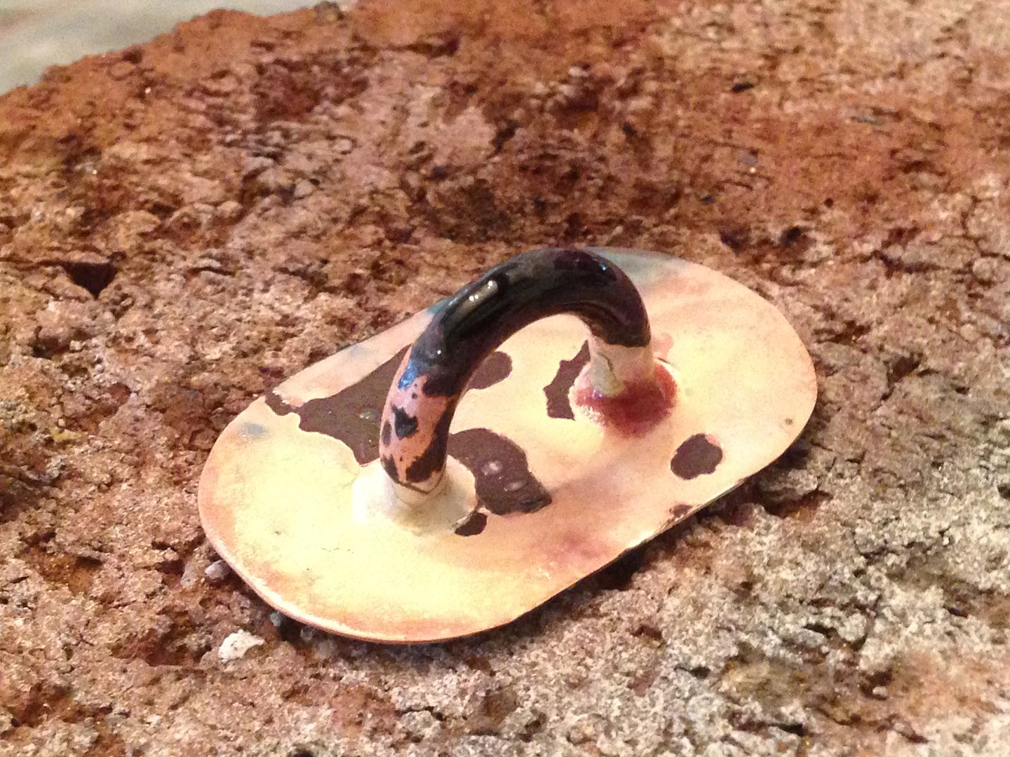
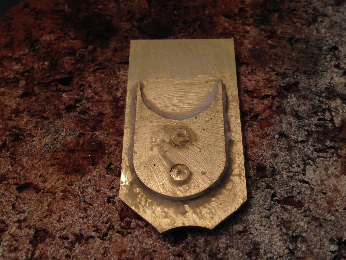
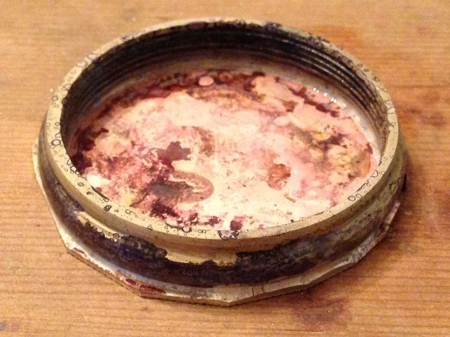
Plenty of flux.
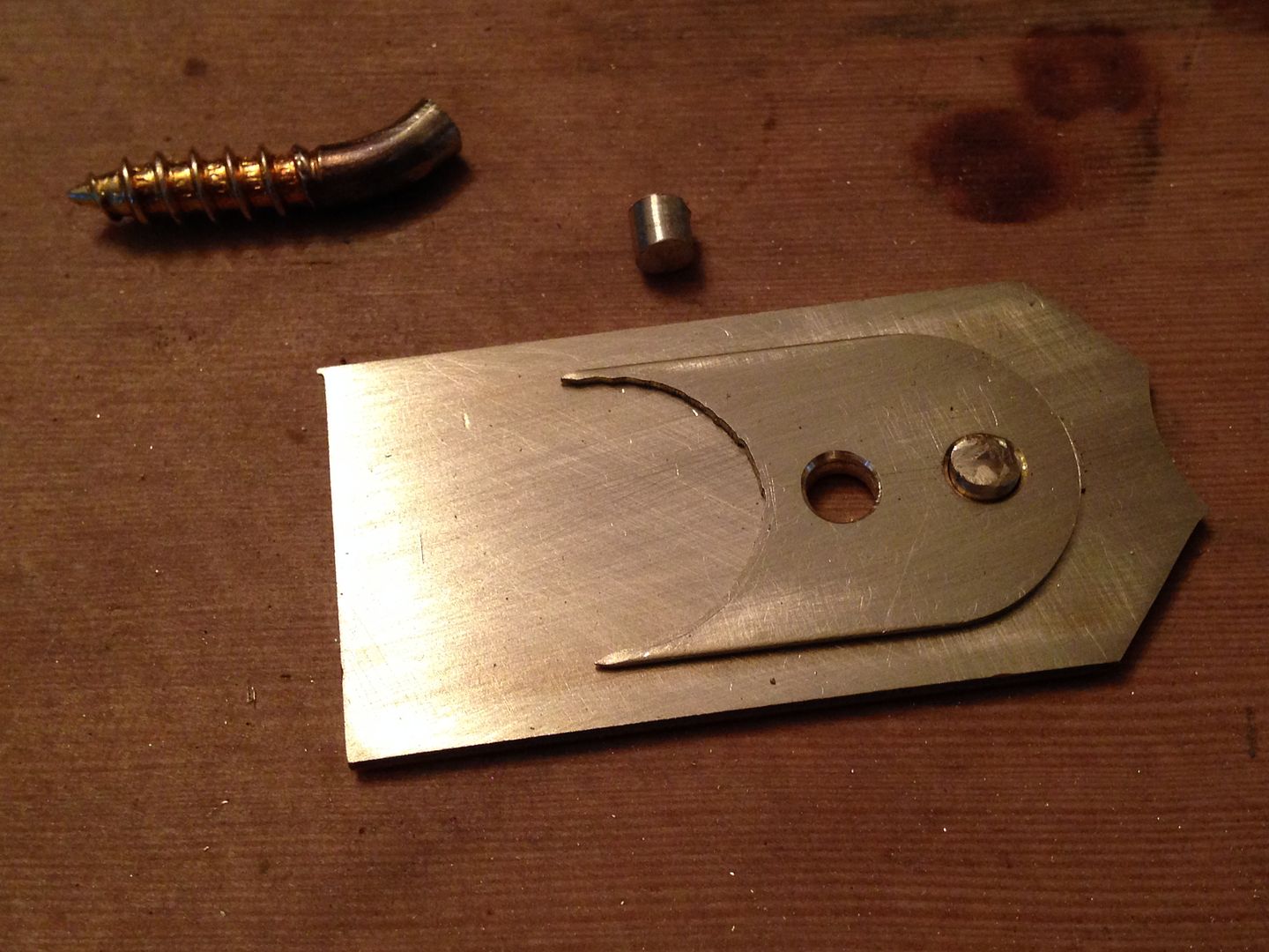
After cleaning it up I drilled some locator holes and wired 1/2 of the threaded union cap I’d made earlier to it and added more flux.
I stopped taking pictures for a bit but here it is brazed onto the tube with the excess filed off.
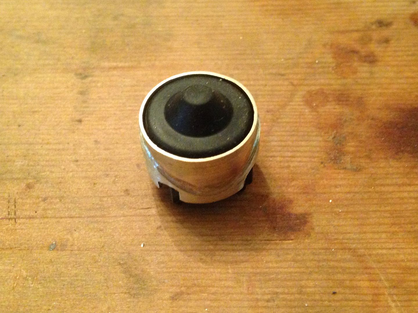
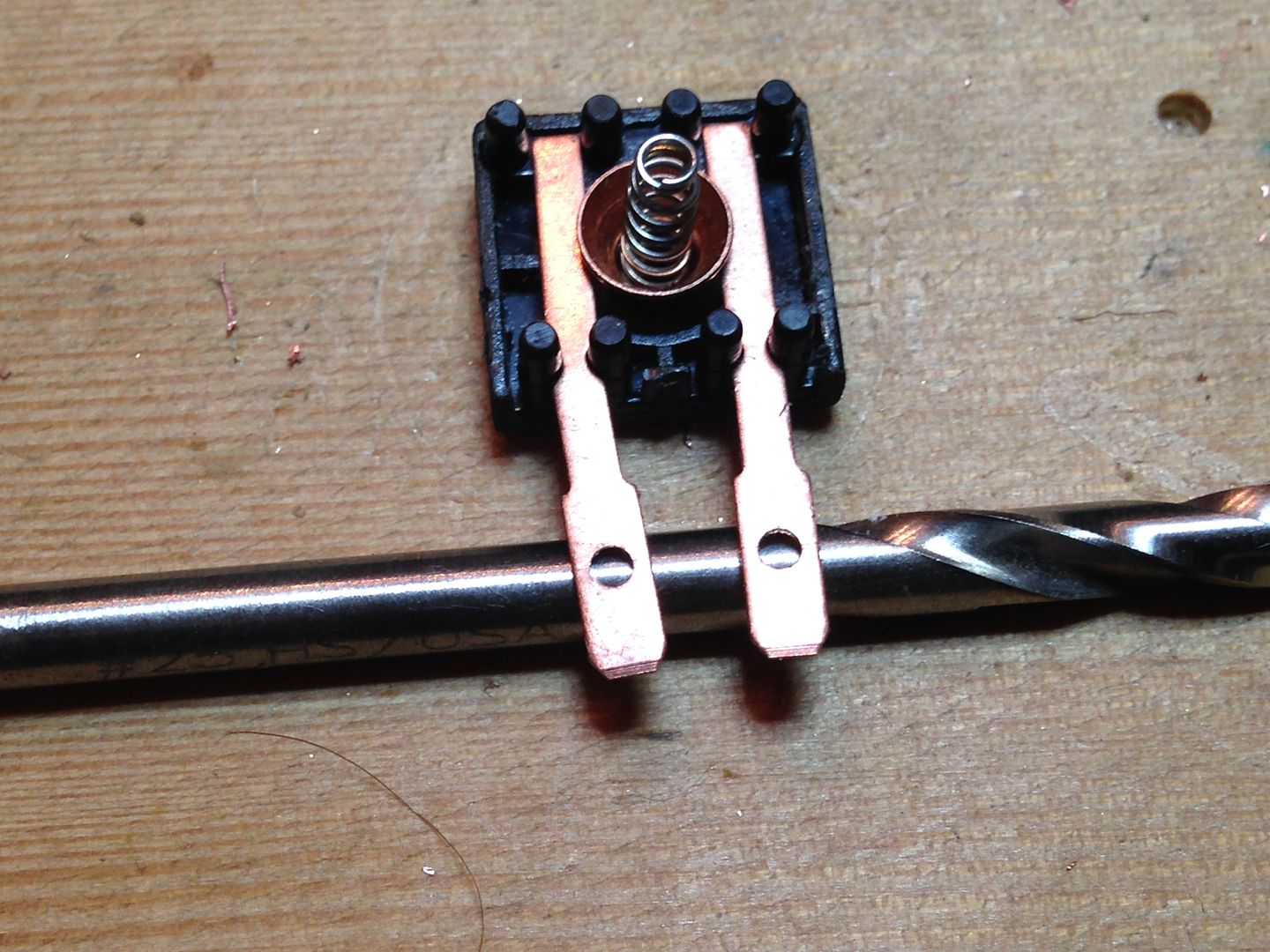
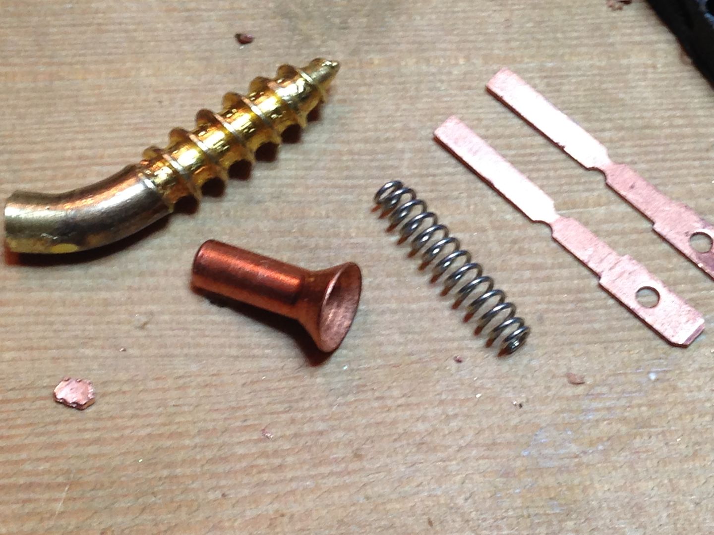
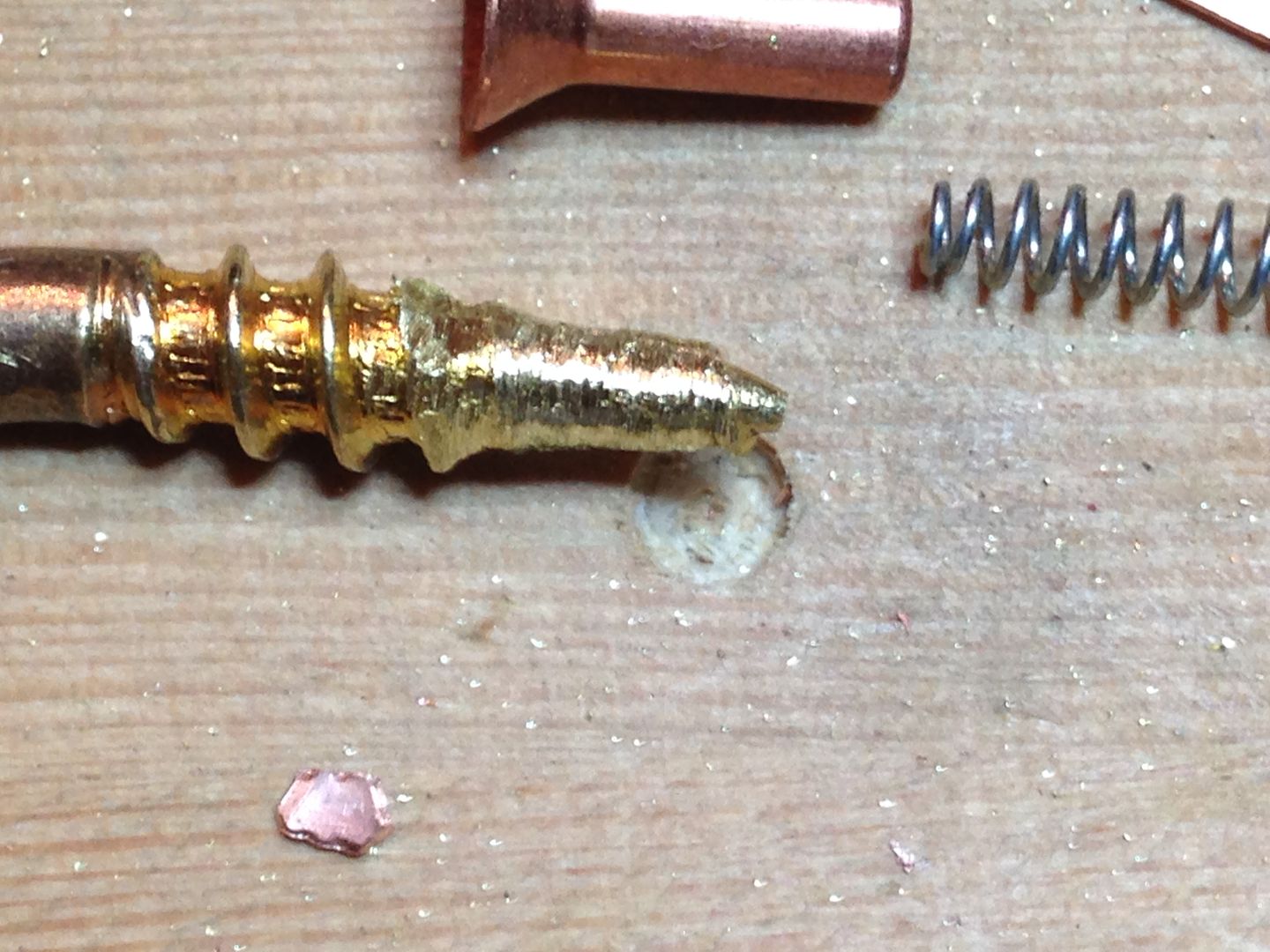
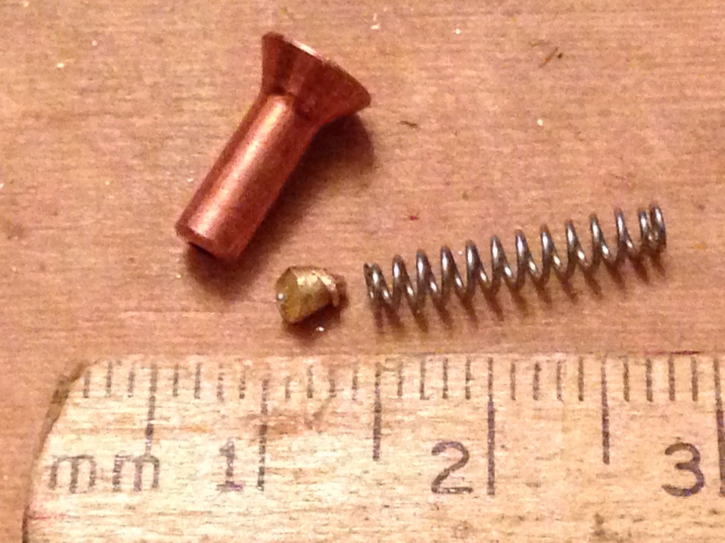
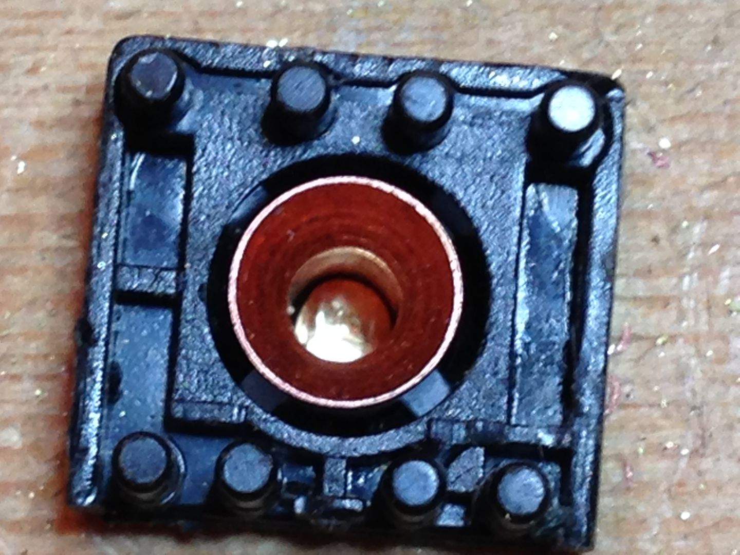
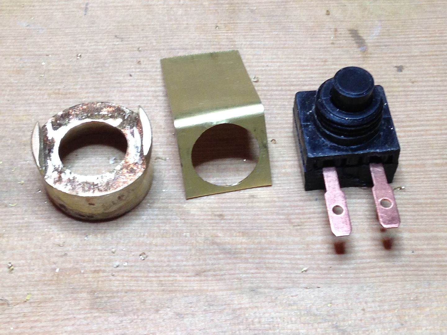
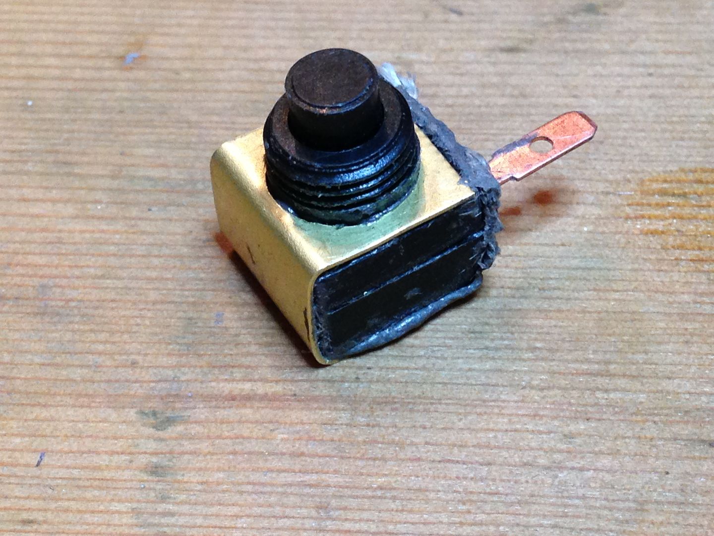
Next is some work on the switch which belongs in the Brass in the middle section.
5/13
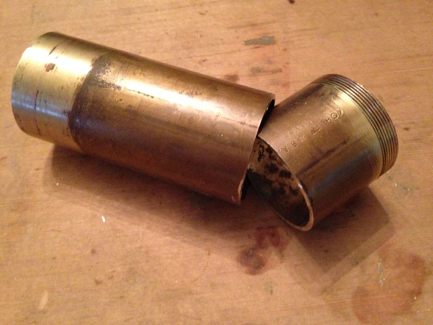
Started working on the head by cutting up this tub drain. Edit- I used the tube and the ring it threads into.
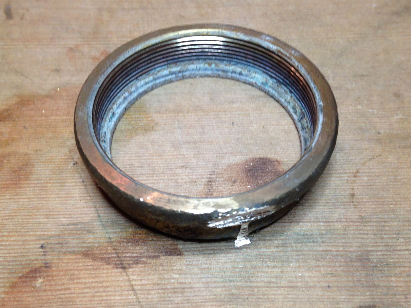
Then had to backtrack and file the threads off the reflector for it to fit in the tube.
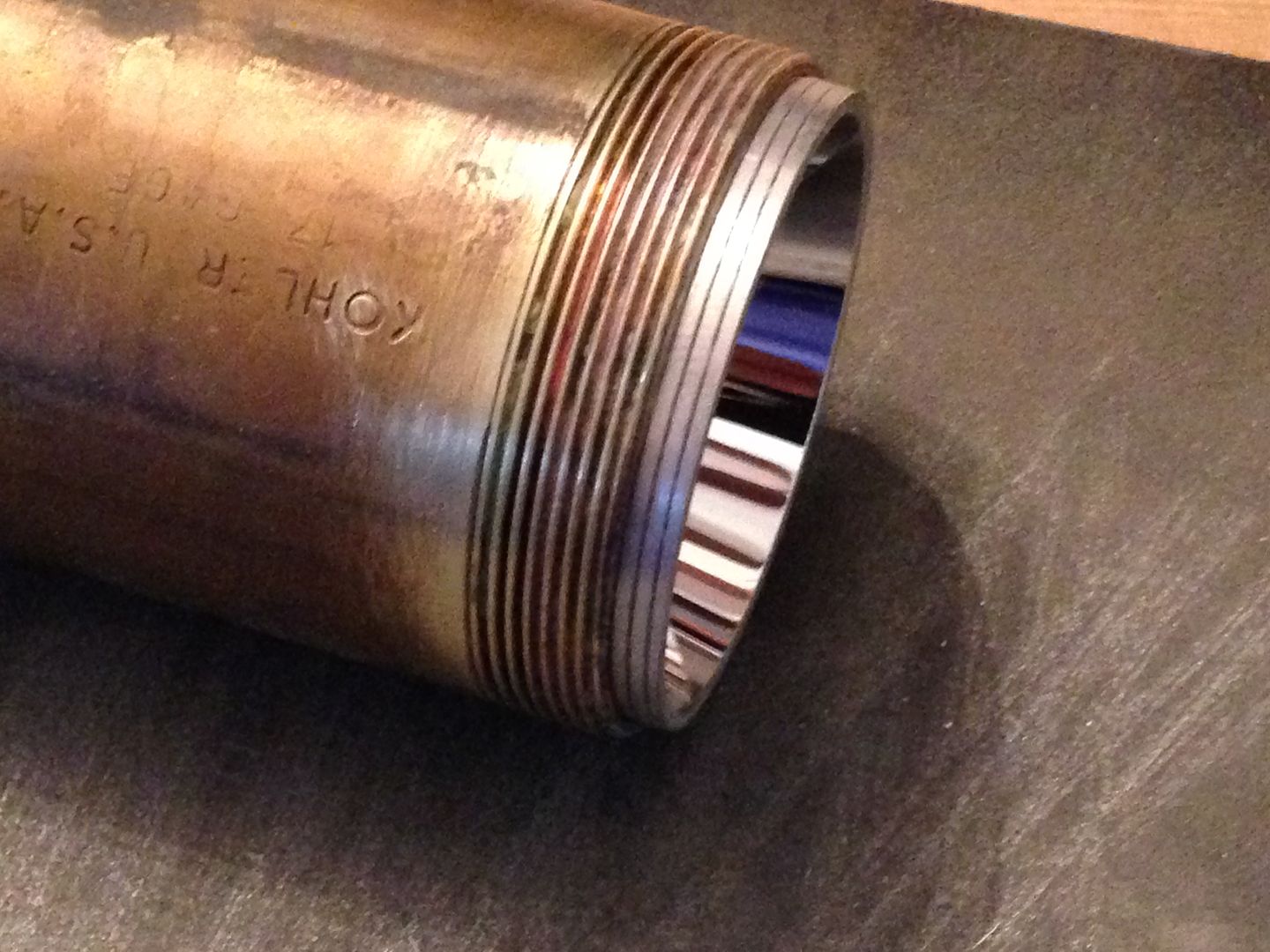
Here is the tube with ~35mm cut off. I won’t be using that much but need the extra to put it together with the next piece.
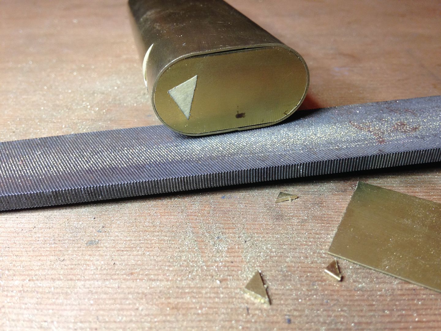
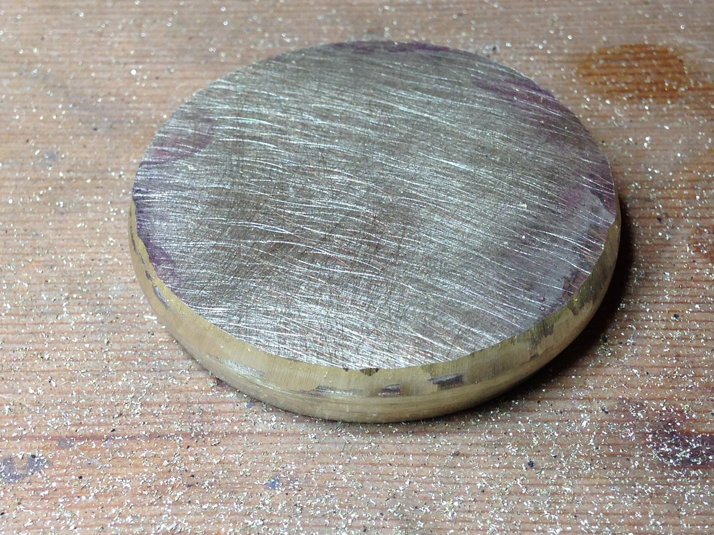
I found a compression fitting that is just a little loose in the tube so I brazed a brass plate to one end and trimmed that to fit the tube. I’ll cut/grind the flats round and cut out most of the middle of the plate after it’s brazed into the tube. Here it is after brazing the plate and snipping the excess.
And after filing to fit the tube. The part of the tube below the plate will be cut away after brazing so that the outside steps down in diameter as the reflector gets smaller. A ring will be added above the plate for the reflector to rest on and take the pressure of the lens instead of the led substrate.
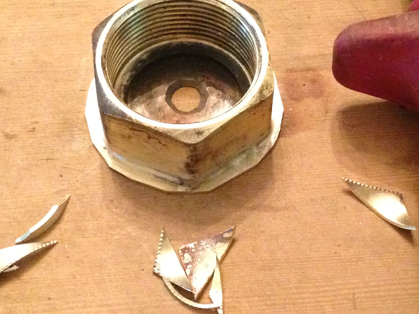
The various pieces of the head step down in diameter so each one gets located a specific distance from the lens. Most of the plate on that last piece gest cut out to allow the reflector to fit through. That part is the second step with the tube being the first and this next part the third. Here it is after rough boring.
And after reaming it a bit. The other half of the cap that I turned smooth and cut is a slip fit into this piece. When I’m done hacking away at this part the two will be brazed together and fins soldered onto the outside.
And here it is again after removing the corners with a hacksaw and some grinding.
Don’t worry if none of this makes sense now. It probably won’t make any more sense later.
5/16
Got enough done on the head that it’s starting to look like something but I changed the way I set it up for brazing. First I cut the center out of the plate/step and trimmed the tube back leaving –3mm extra.
I want exactly 14mm from the step to the threaded end of the tube so I cut 14mm from the recent off cut and resized it so that a 12g wire separated the two tubes. The shallow kirf keeps the wire in place.
Here it is partway in.
G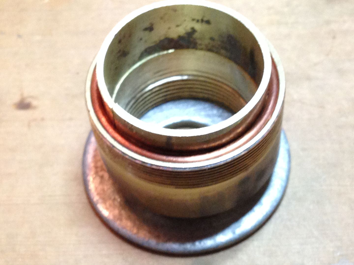
And pressed in the rest of the way and flipped over. If this works right the step will be just right and the shim won’t get stuck.
Loaded with flux and awaiting six bits of brazing wire.
Whoopee, it worked!
Trial assembly.
Now to trim the excess from the tube and start grinding.
A bit more.
Here it is with the top section and bezel ground and sanded. My spinning bolt is a long 1/2” carriage bolt with the head cut off and chucked into my cheapo drill press.
Then I removed the top section, reversed the bottom and worked it over.
Not done yet but starting to look like something.
Plenty of work left to do on this sanding the small end smooth, adding a plate to the bezel, along with some stops on the inside and fins on the outside. The only brazing left to be done here is the bezel. The rest of the head is just soldered. Not sure what I’ll work on next.
5/20
Decided to work on the bezel as the hole that later gets enlarged leaving just a lip starts out small enough to help stabilize the head when I spin it to smooth the fins.
I started by brazing a plate to the bezel ring which began as part of the tub drain. Edit- I was able to flip this ring and liked how it looked with the lip toward the front much more.
And after preliminary trimming and cleanup. Dumping the hot part in boiling water loosens the brazing flux which hardens to a scale that’s hard to remove otherwise.
Next to mark the center measuring from the inside. This part was cast not machined so it’s unlikely that inside and outside diameters are concentric.
I started out using a 3/8 bolt to spin it and I will definitely have to true it up by hand before it’s finished as the sidewalls of the bezel ring are not a consistent thickness but even so it’s coming along.
I also did some work on the pills using the bored out threaded coupler from earlier.
I cut open a piece of 1” pipe, annealed and flattened it for some discs.
And cut some 1/2” pipe and coupler pieces along with the discs.
These parts were brazed and cleaned up.
One of them didn’t turn out too well. I don’t care about the off center plate as that gets trimmed but then inner tube didn’t end up in contact with the inner plate.
That was a fail so I cut some new parts and did it again but slightly differently.
The two plates on this part were recessed using two stacked brass washers as shims. With just a little filing, a 16mm sink pad fits nicely and self centers.
That wouldn’t work well on the MT-G star so I’ll have to do something different to center that one. First I notched the sides partway for the wires.
Then I made a jig from two pieces of aluminum pipe and a strip from a soda can. The strip and tubes are snug to the copper pipe and the 20mm just slips in.
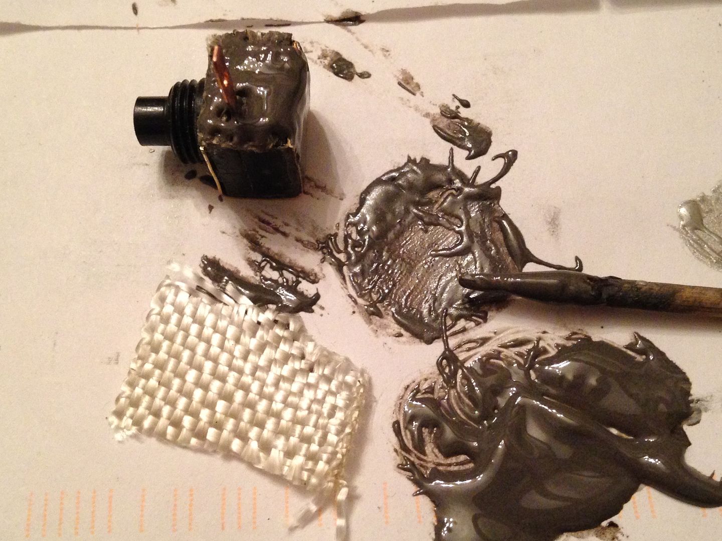
Then it was simple solder them. I used flux to coat the surfaces and cut a short piece of solder to go under each pad and heated them with a small torch. When the solder melted I pushed down on the stars to squeeze out the excess.
The last soldering operation before the LEDs get reflowed is the threaded collars but I have to file down the Noctogon first and determine exactly where to solder the collars so the LEDs end up the same. The XML get a spacer disc but the mtg only gets some kapton on the substrate. There are a bunch of different parts coming together now but still a ways to go. It may not get done in time for this years trip which is now only a week away. Oh well, I’d rather take a good piece next year than junk now.
6/4
Did some more brazing practicing on thin brass for a difficult piece coming up later. This was 25mm wide .4mm thick brass flat stock that I annealed and bent into a tube. Rolling it sandwiched between two pipes( inside one and outside the other) makes it nice and round. Getting the seam so it’s flush without pressure helps to keep it from getting wonky when heating it.
A bit of cleaning and sanding ( a lot, actually) and it’s a nice snug fit. This piece will be cut to form spacer rings between the brass fins on the larger middle section of the head. Can you see the seam? It’s right there starting at the tiny nick on the right.
And a second smaller tube from the same stock. Note the tiny notch where it didn’t fill.
One more showing where it goes. See that notch again?
I did some other work on some driver bits but that post will have to wait until I can finish and test the results.
6/09
Spent a good deal of time cutting fins and spacer rings since last night. First a 1” hole saw.
Then a 1 3/4” hole saw.
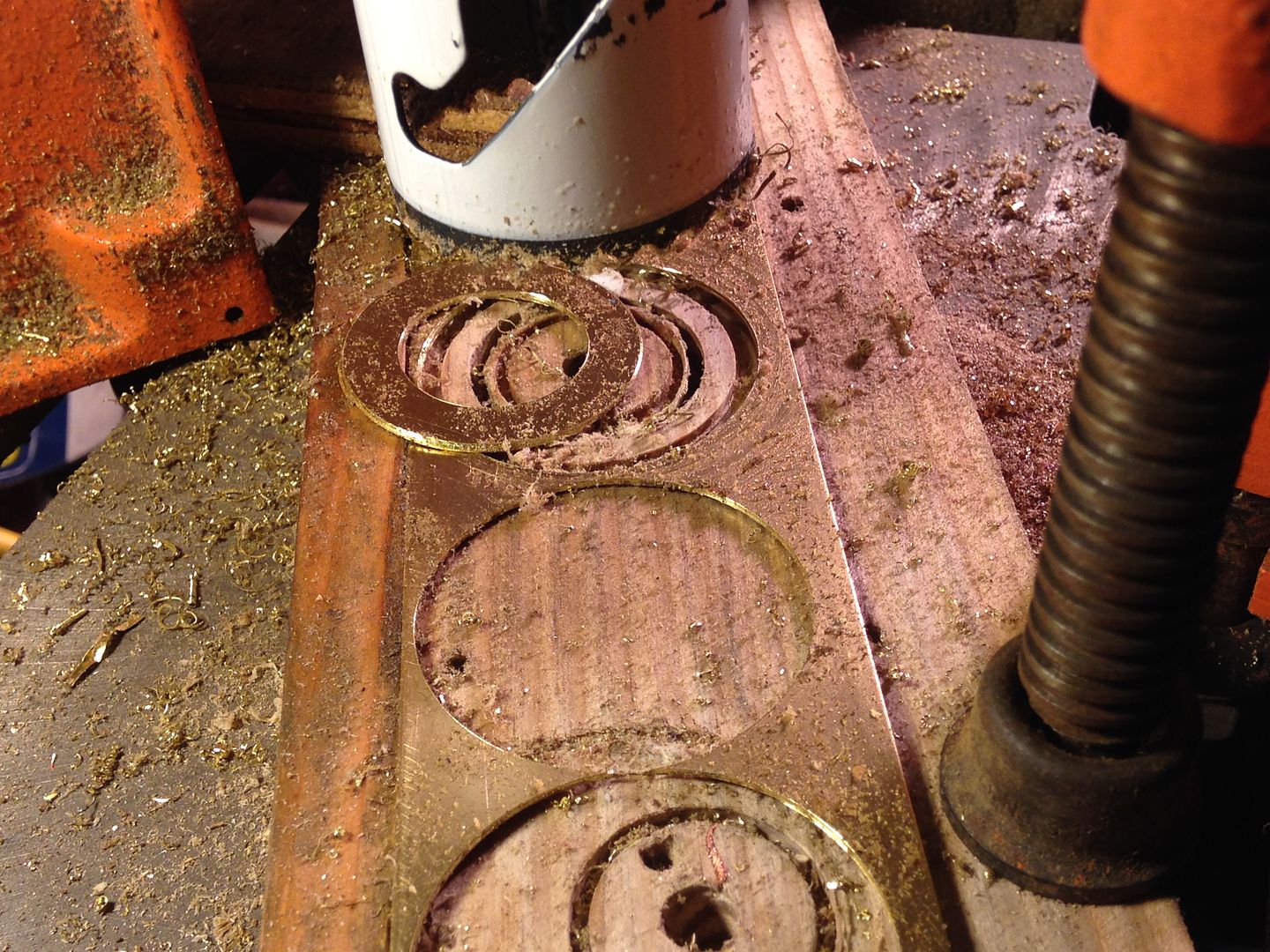
I made 5 of these. For the larger end of the head I was able to nest a 1 1/4” hole saw with the 1 3/4” hole saw. These are a loose fit but since they are mostly cosmetic on this part of the head I don’t care. The first 5 didn’t quite fit so I wrapped tape and sandpaper around a 7/8” hole saw and reamed them to fit.
It didn’t look like much but took about 2 hours of sanding before they fit.
Next I needed to cut the spacer rings from the tubes I had made earlier. I used a Dremel wheel in the drill press to do this, slipping a bit of copper into the kirf once I had gone half way around. I cut the rings just under 3mm and sanded them to fit. After each cut I dressed the remaining tube with sand paper on my work ply.
At the step between the 2 sizes I added a second ring layer cut, resized, and brazed from some round brass tube.
Here they are after a rough clean up. 
And again stacked up on the head.
I’ll need to solder them on and grind much of them off giving the head it’s final shape. Once that’s done I’ll enlarge the bezel opening to match the reflector and the head minus the LEDs will be done.
6/12
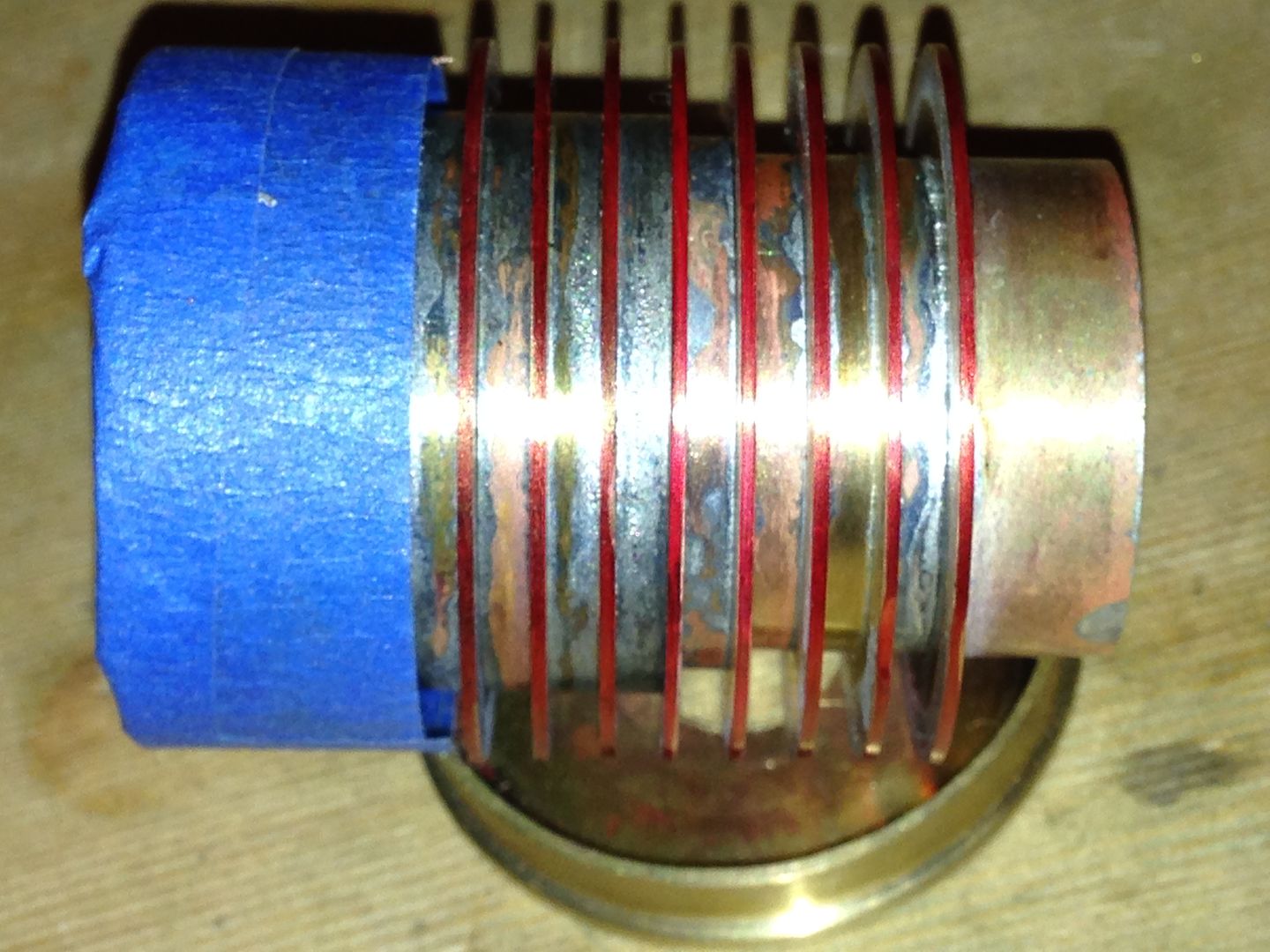
I soldered up the head this evening.
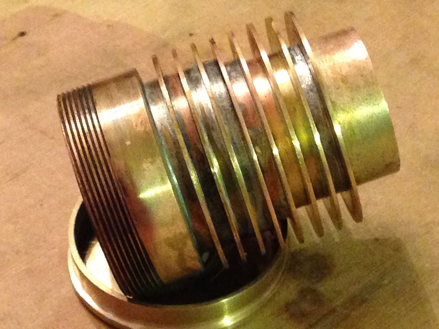
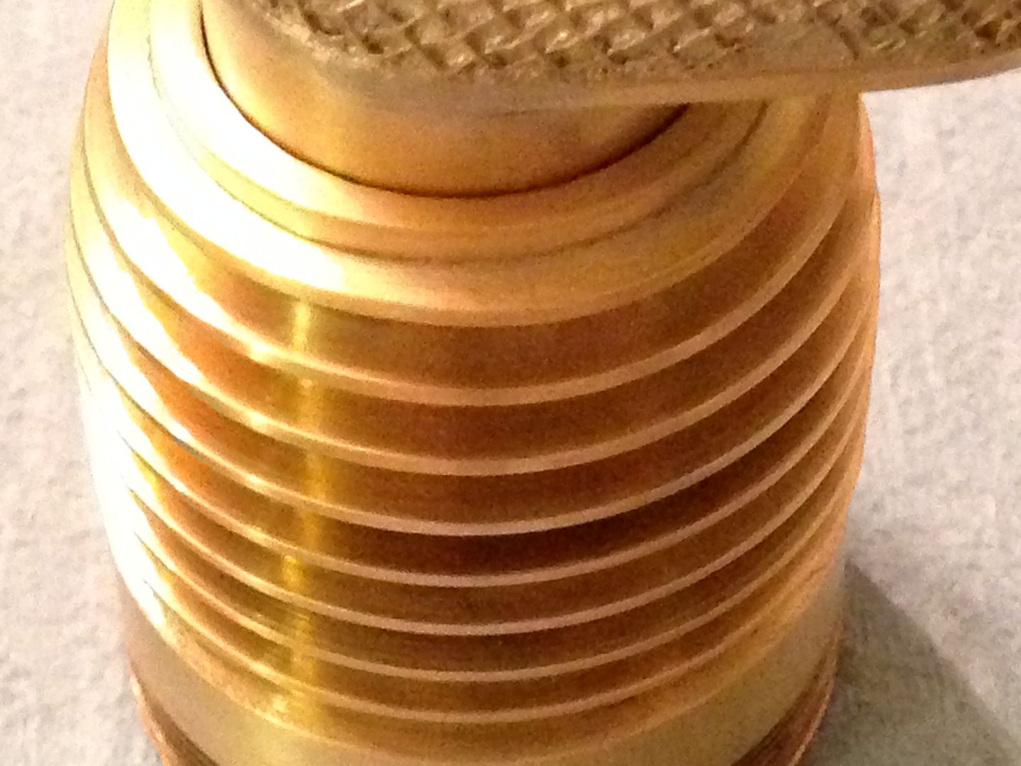
Then taped over the threads to protect them and put it back on the bolt to spin it in the drill press. I put some red magic marker on the edge so I could tell when they were all even.
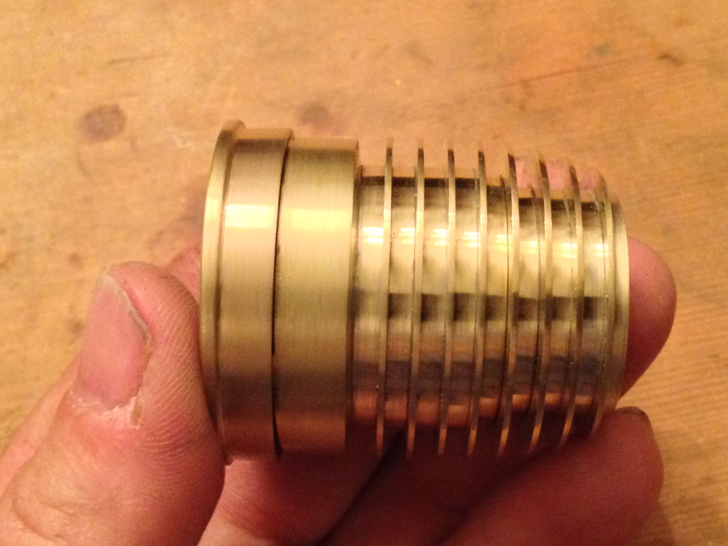
A couple hours later it looked like this.
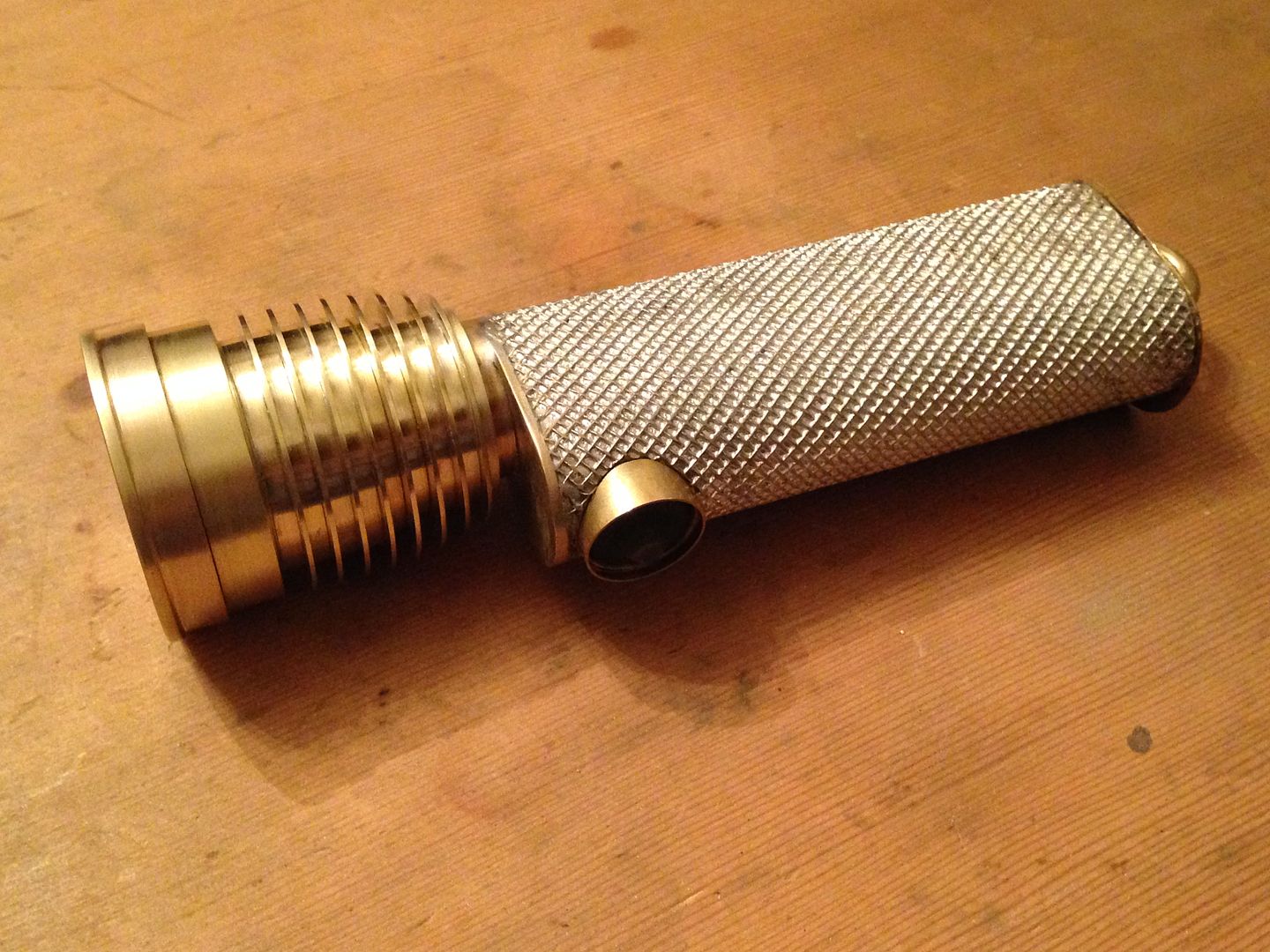
And mounted on the tube.
Next I get to open up the bezel.
6/14
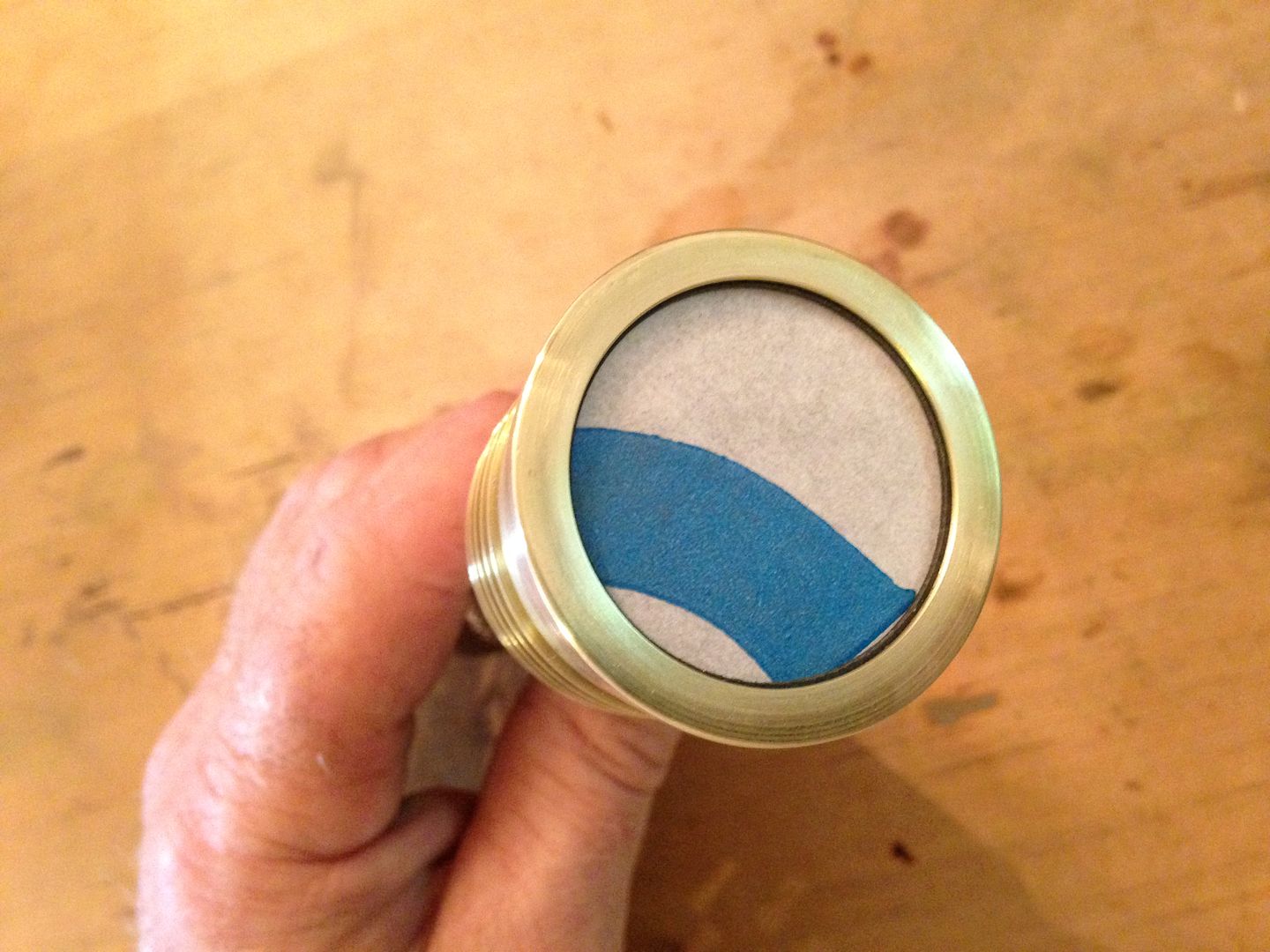
Finished up the bezel using a 1 1/8” hole saw and reaming it out to 33mm(reflector opening id) using the same technique I used on the fins. The lens has a paper coating on both sides that I left on a bit longer.
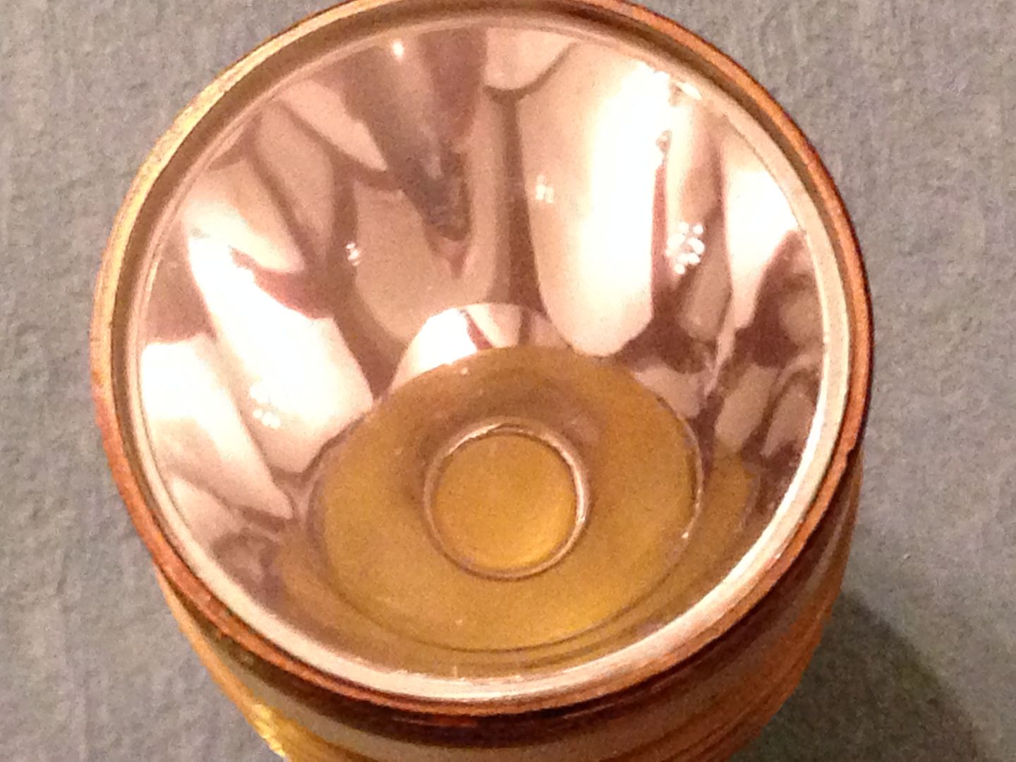
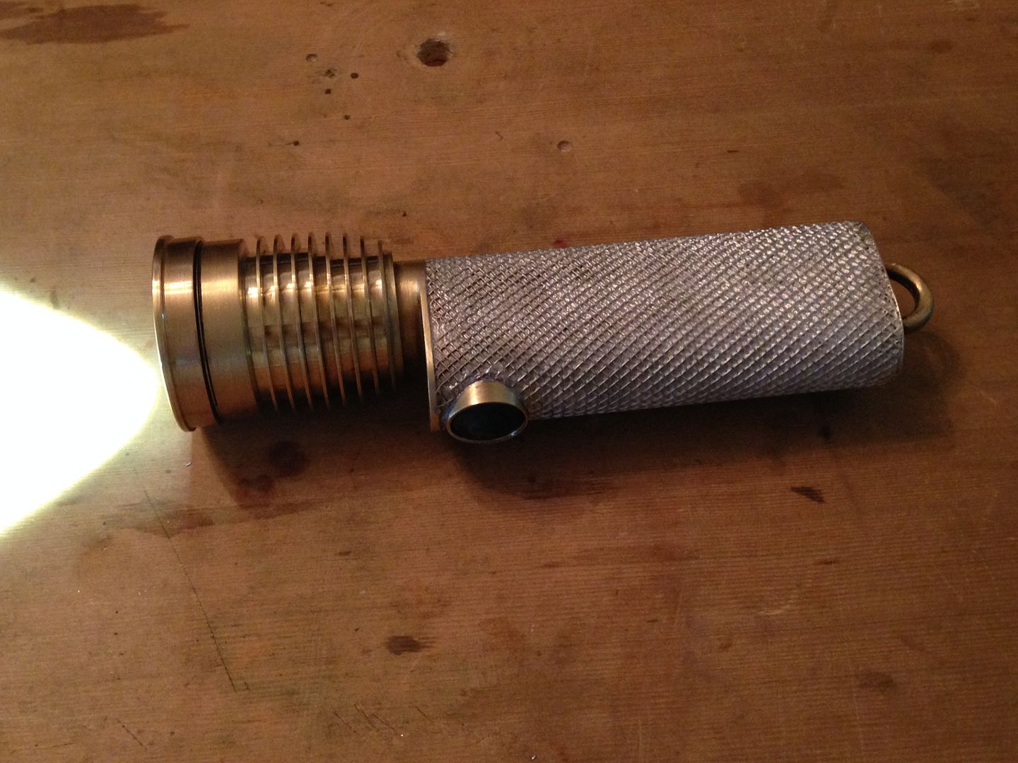
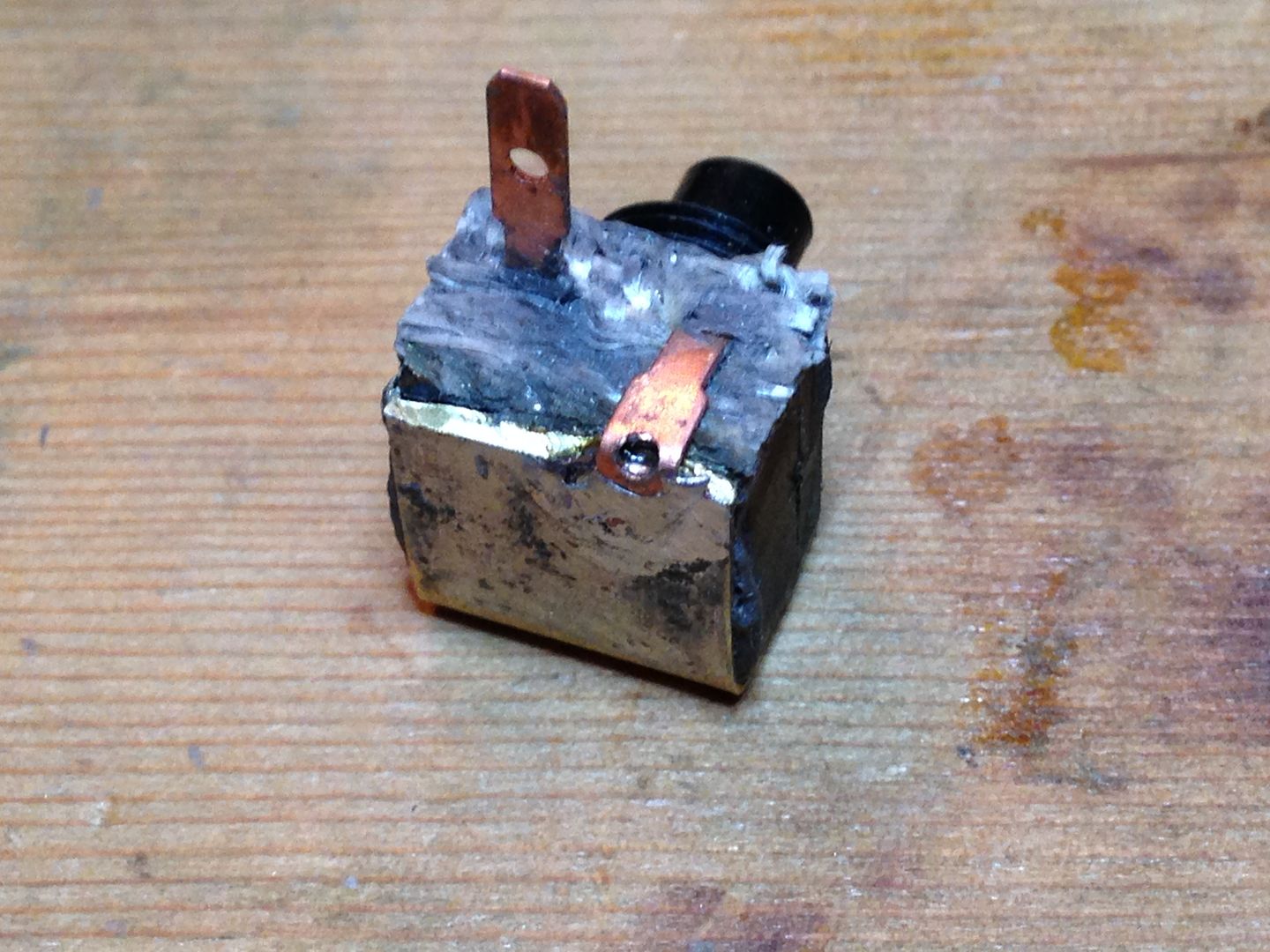
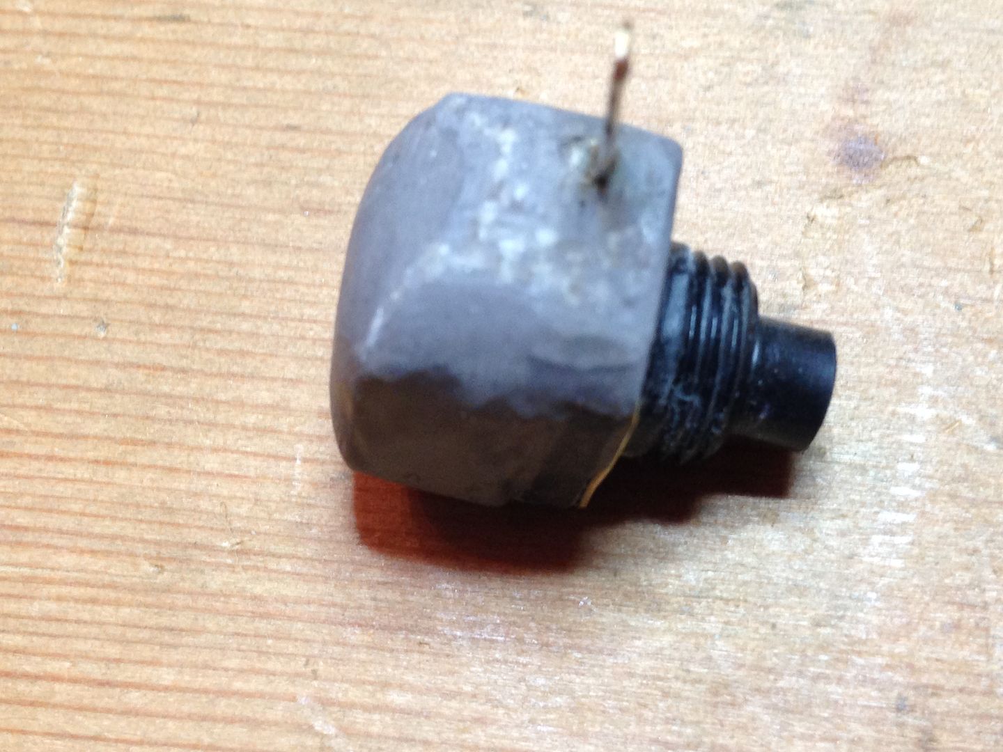
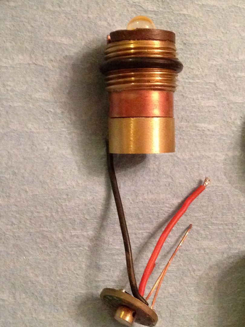
I finally took the plunge and reflowed my led from an aluminum star onto the copper pill w/brass threads. The extra brass bit on the bottom holds the driver and fills the gap between the pill and B+.
The o-ring in the middle rests against a stop( the other half of the threaded piece brazed to the top of the battery tube) and is a snug fit(needs silicon grease to slip in easily). It is stretched over the pill and completely fills the gap to the outside as well.
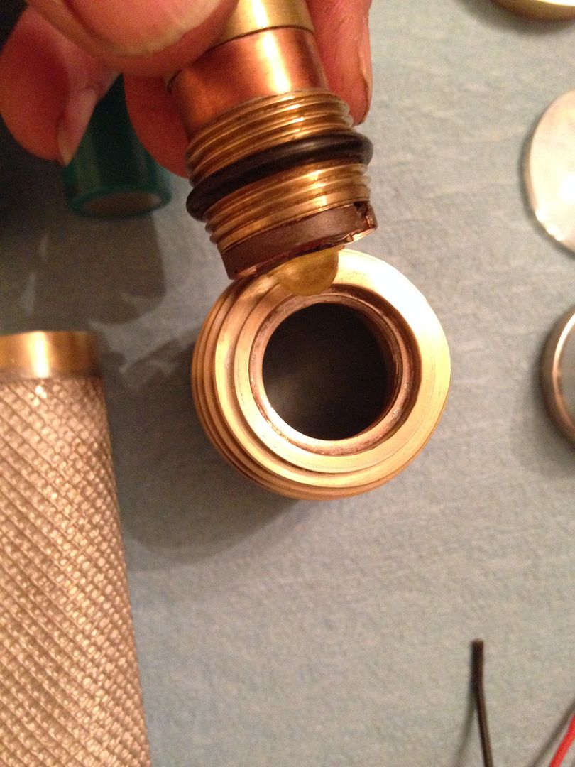
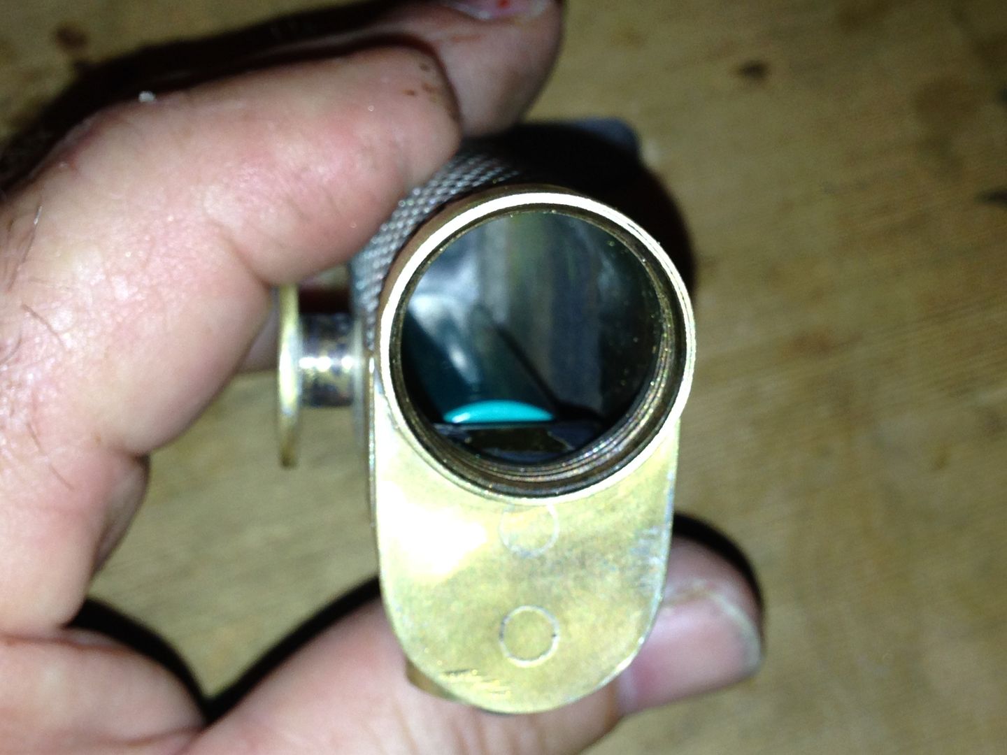
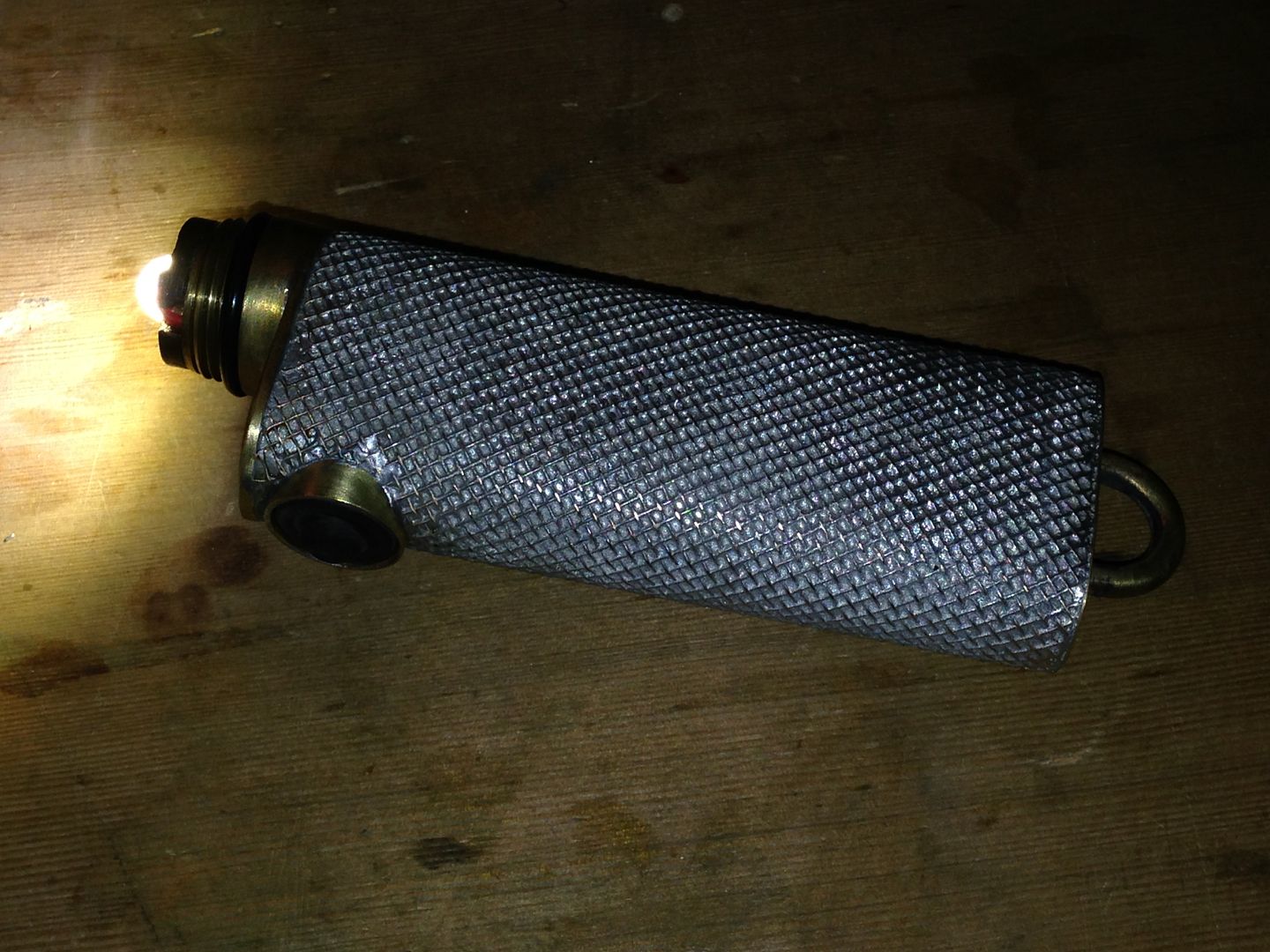
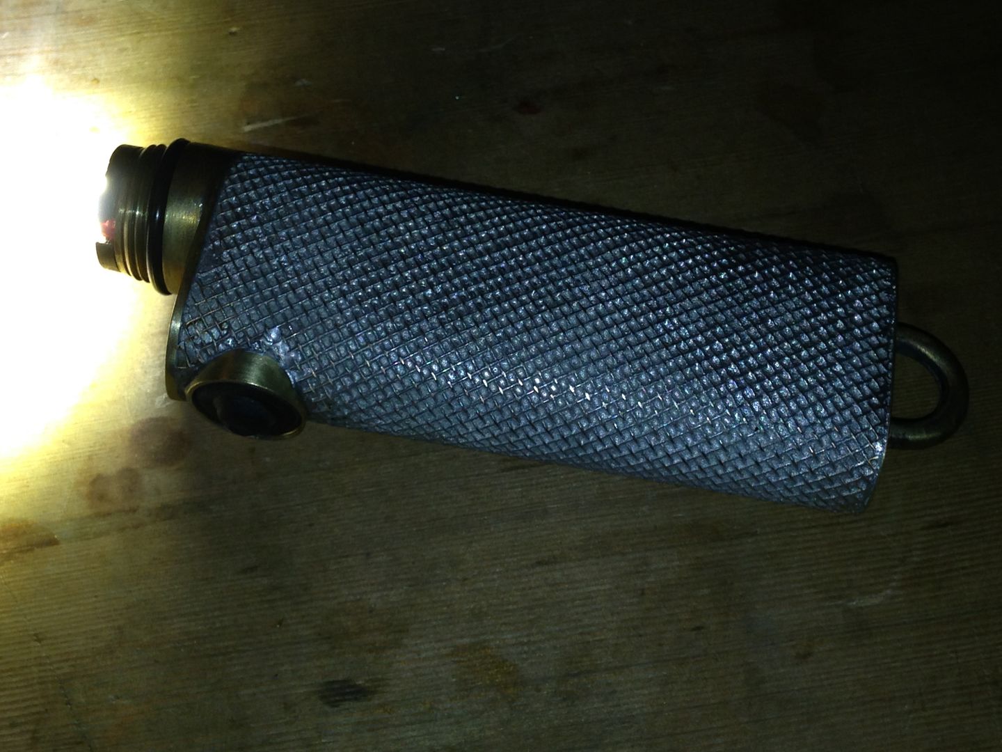
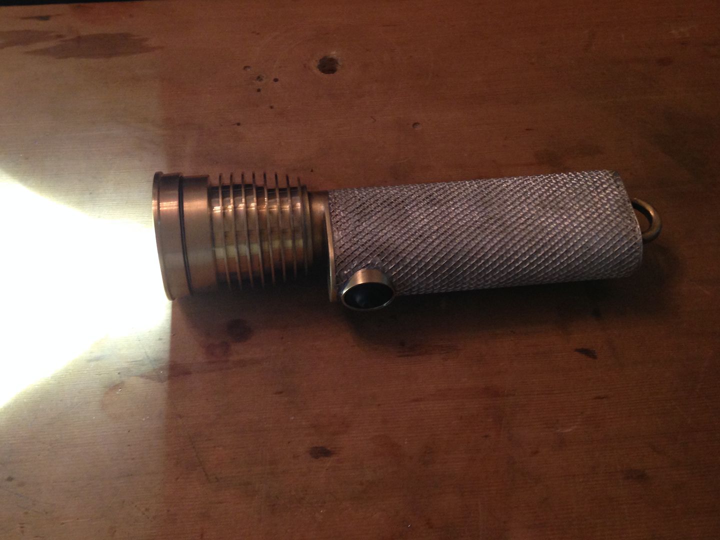
Here it is threaded into the head.
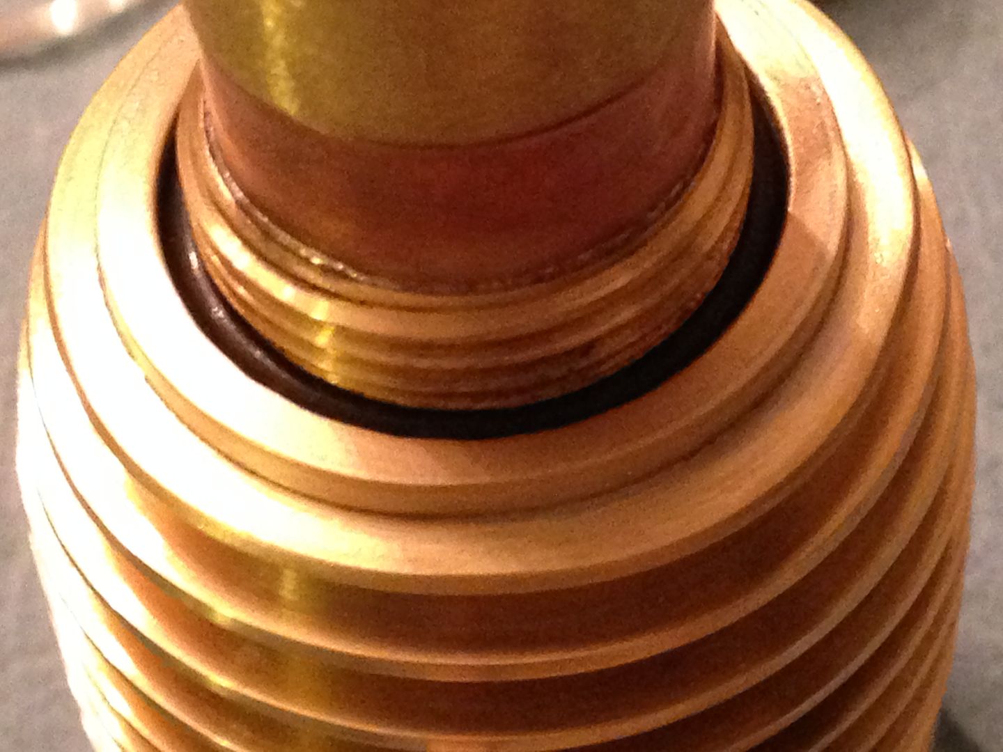
When also threaded to the body the o-ring is further compressed against all surfaces.
I’m more confident of this being proof against leaks than I am about the switch working properly but time will tell.
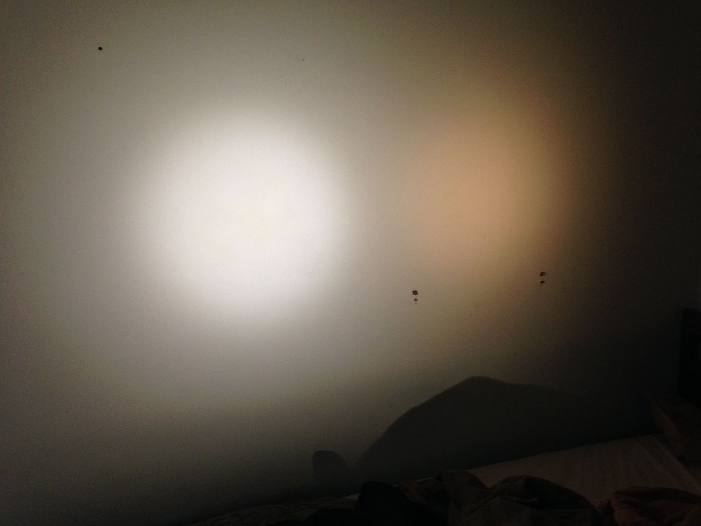
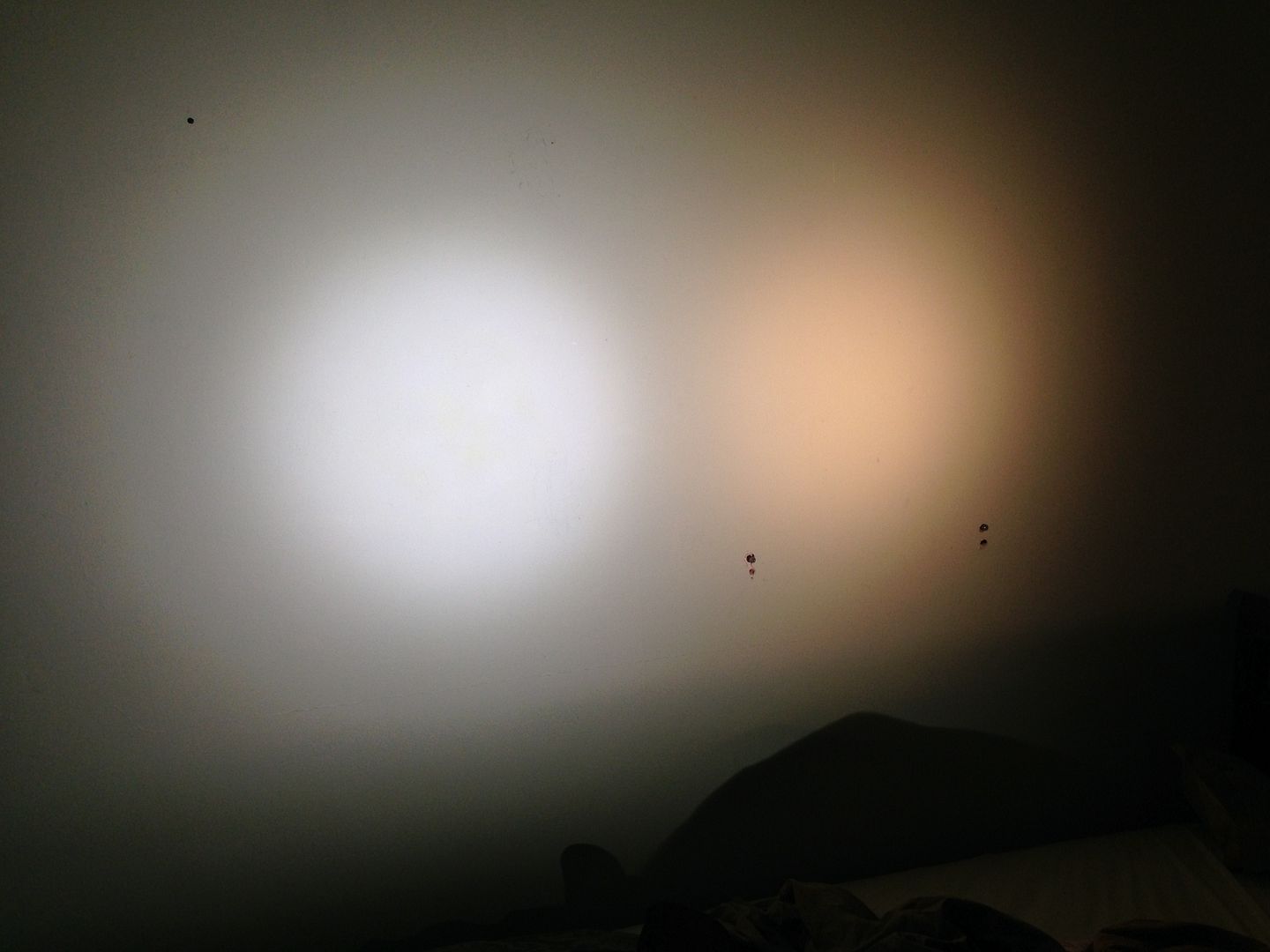
Once the led was in place I pulled the coating off the lens so I could see how the lens, reflector, and led fit together.