Might have a couple of minor things wrong there. The 4R7 resistor should be between batt+ and the reverse polarity protection diode - this one is important for the 25/45/85's.
Pin #6 for the FET gate looks all good and typical in our BLF FET drivers. I'd replace the SIR800DP because it's probably a Chinese fake, with a SIRA20DP FET - better.
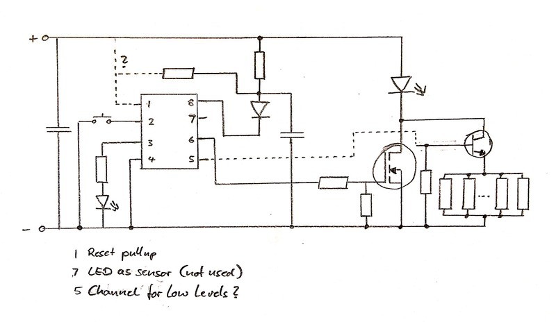
I think pin #3 drives the resistor bank for low amps, including moonlight.
Pin #7 can be ignored - think that's TK's pin to read a signal back from the LED for possible light programming.
I've done a very similar Anduril config, but haven't done one for the TA resistor bank - don't know what it max's out to. TA should be able to help.
Thanks Tom - I’ll look into it more. I’ll take the driver out tonight and take some good high-res photos, but I used ChibiM’s photo (from his “modding” post) and then used a multimeter to test connectivity.
Not sure I should ask here or in the other thread, I’m trying to get an understanding of this stuff to hopefully mod a MF01 with tint ramping with lexel dual buck driver, looking at the lantern config file I see that it isn’t thermally regulated, and there’s this comment part about USE_SET_LEVEL_GRADUALLY
In the fsm-ramping.h file it says this is for adjusting “brightness very smoothly” , so how not very smoothly it will adjust the brightness during thermal regulation without this ?
Yeah, there is definitely a lower channel not showing in the diagram above - there has to/must be two channels. SammysHP's diagram looks more reasonable.
The big bank of resistors in TA's drivers in controlled from the MCU as a lower channel - I'm positive of that.
Did you PM TA about it? Or post to a thread he actively monitors and replies to? I doubt he follows this one.
The GT90 driver uses the same firmware as the GT70. It is the same driver as the GT70, They just adjusted the resistor values to work with the GT70 firmware instead of adjusting the firmware for some reason.
So any firmware that works with the GT70, would also work with the GT90.
I don’t remember off hand the pinout of the MCU but it was a standard pinout when I made it.
The resistor bank handles the low modes, then it brings in the main FET, this gives a smooth ramp compared to just using the main FET (although the changeover can be tricky to get smooth).
It then uses the voltage divider for LVP.
Another pin is used for the e-switch
Another pin for the lighted switch.
Pretty standard stuff, the above diagram looks like the right pinout at a glance.
Here are some pictures to help:
This is a layout file for diptrace, it is hard to read as it is only setup to make routing the pins in diptrace easier, not to look at. Still could help:
Is this a reasonable place to put feature requests? There’s one that came up over on reddit that I think was a good idea, if practical.
Could you add an option to automatically go into lockout mode after some period of inactivity? It would be another way to reduce the chance of burning a hole in your pocket while interfering very little with normal use of the light. If you could set the timeout in minutes with a maximum of 60 or 90 I suspect a lot of people would find it useful.
Yes, sorry, the auto-lock feature is in the anduril2 branch. It’ll get merged after I finish solving the Rubik’s cube of button mappings, and after some extra testing.
It doesn’t keep the MCU awake while counting. It uses sleep ticks for the timing instead of waking ticks. This keep power usage low, but also makes the timing less precise.
In particular, there are about 7.8 sleep ticks per second, which it rounds up to 8 for integer math purposes… so it ends up with “minutes” which are about 62 seconds long. I should probably revisit that part of the code to see if there’s an easy way to improve that.
I’m also trying to make it easier/faster to use lockout mode most of the time instead of “off” mode. Because some lights just can’t be trusted in a pocket.
(found the above in one of your posts in an LT1 thread)
I’ve noticed something on my lights that I’ve recently updated (3/18 builds). When I use voltage check, often the first (and sometimes second) readings are way low. I’ve gotten voltage checks that go 3.3 -> 3.8 -> 3.9 (and then stable at 3.9) and similar results. It’s pretty frequent, and I made sure to check when the light had been out of use for a while (rather than, for example, after a turbo run where the cell voltage might be rebounding). This is also happening both on a few lights using ATTiny85 pin 8 to read voltage, as well as one using pin 7 to read voltage from a voltage divider.
Any ideas? My FW3A is among those that I flashed and is therefore affected, and did not behave this way on whatever original firmware version it was running (something old, it’s a purple version). (None of the other lights ran Anduril before, so I made sure to check that one too.)
I can think of a way that would happen on FW3A since it doesn’t have aux LEDs (and thus doesn’t have sleep ticks enabled).
The way the ADC code works now depends on whether the light is awake or asleep:
If asleep, the raw ADC value is used directly, so measurements reflect the exact value at that moment.
If awake, the raw ADC value goes through a very strong lowpass filter which takes a few seconds to adjust to large changes.
So on lights with blinkable aux LEDs, the value gets reset to the raw battery value every time the light is turned off, and then waking readings happen more slowly.
But if the light doesn’t measure while asleep, like on the FW3A, it only has the slow adjustment mode. It would retain whatever value it was last at while awake, regardless of how long it’s asleep, and then adjust slowly from there next time it’s on.
I suspect it could be fixed with a small change in the code where it decides whether to use the lowpass filter or not… something which checks whether the light just woke up. The thermal code already has a mechanism like this; it’s only voltage which doesn’t… and it likely only affects lights which have sleep ticks turned off.