I took a first stab at fixing it, but I still need to test it. If it works, it seems to cost about 14 bytes.
My Supfire M6 does it the most, and it’s using the 3/18 ROT66 build currently. The driver is a Lexel derivative of a TA triple-channel for the Q8. (I can post further details if needed.)
I’ve also reproduced it on my FW3A and my Convoy L6. I can’t remember if I’ve gotten it on my D4. I’m trying to narrow down the conditions under which it happens… The M6 seems to miss every time, although sometimes it’s way off (as much as 0.5V) and others just 0.1V. (I’m comparing the first reading to the stable readings I get one or two readings later, and not dealing with the actual voltage calibration.)
Both the FW3A and the ROT66 have TICK_DURING_STANDBY disabled. Basically, if there is no aux LED, or no “blinking” mode on the aux LED, it probably has no “sleep ticks” and is thus likely to have this bug.
If you have one which is relatively easy to reproduce the problem on, and also relatively easy to flash, I sent up a potential fix in fsm branch r486.
I tested it on an original Emisar D4, and it appears to fix the problem. What I did was:
- Turn the bench power supply down to 3.0V.
- Turn the power off, click, and turn the power on to force the light to reboot.
- Turn the light on for a few seconds to let it read voltage, then turn it off.
- Change the bench PSU to 4.2V.
- Click 3 times to enter battery check.
Before the change, it’d take about 3 cycles to reach the correct voltage. After the change, it goes to the correct value immediately (though sometimes it’s 0.1V off initially, and then corrects by the time it hits the 2nd cycle).
I have not tested thermal behavior in this version though… so that’s a big item on the todo list before it can be considered safe. In addition to the normal regulation behavior, I need to test some corner cases involving large temperature changes while the light is in standby mode. Will probably need to use a hair dryer or something, to artificially cause large temperature swings.
I’m not expecting any problems, but the change did touch some thermal code… so I consider it high-risk. And thermal testing is unfortunately time-consuming.
Further testing seems to point towards your suggestion. I haven’t gotten around to building the new Anduril version yet, though. Procedure to reproduce:
- Give the light a brief turbo run. Just get the voltage to sag a little bit
- Turn the light off from turbo
- Let the light sit. could be a few minutes, or hours if you want, but long enough the battery voltage will be normal
- Go from off -> battcheck
- Observe at least three battcheck readings, or until they are stable.
I’ve reproduced it on the D4 easily now as well with this method. A ten-second turbo blast and turned it off, came back an hour later and batt-check’d it. 3.0, 3.5, 3.8, 3.8 (etc.)
I could potentially just enable sleep ticks on all build targets… and it would make sure the issue doesn’t happen. But I’d prefer to fix the issue properly instead of making sleep ticks mandatory. So that’s what I did.
It’s just difficult to do thermal testing at the moment, so I haven’t verified yet whether it’s truly safe or if there might be some weird effects on corner cases involving large temperature changes while asleep.
I'm inclined to go with this version/fix. Need to grab a snapshot of Anduril this week to incorporate in drivers I'm building/preparing. Let me know if you have plans to test further soon, if not, I'll grab it today.
Thanks TK!! ![]()
I finally got around to giving the new thermal regulation a try. Here is the result:
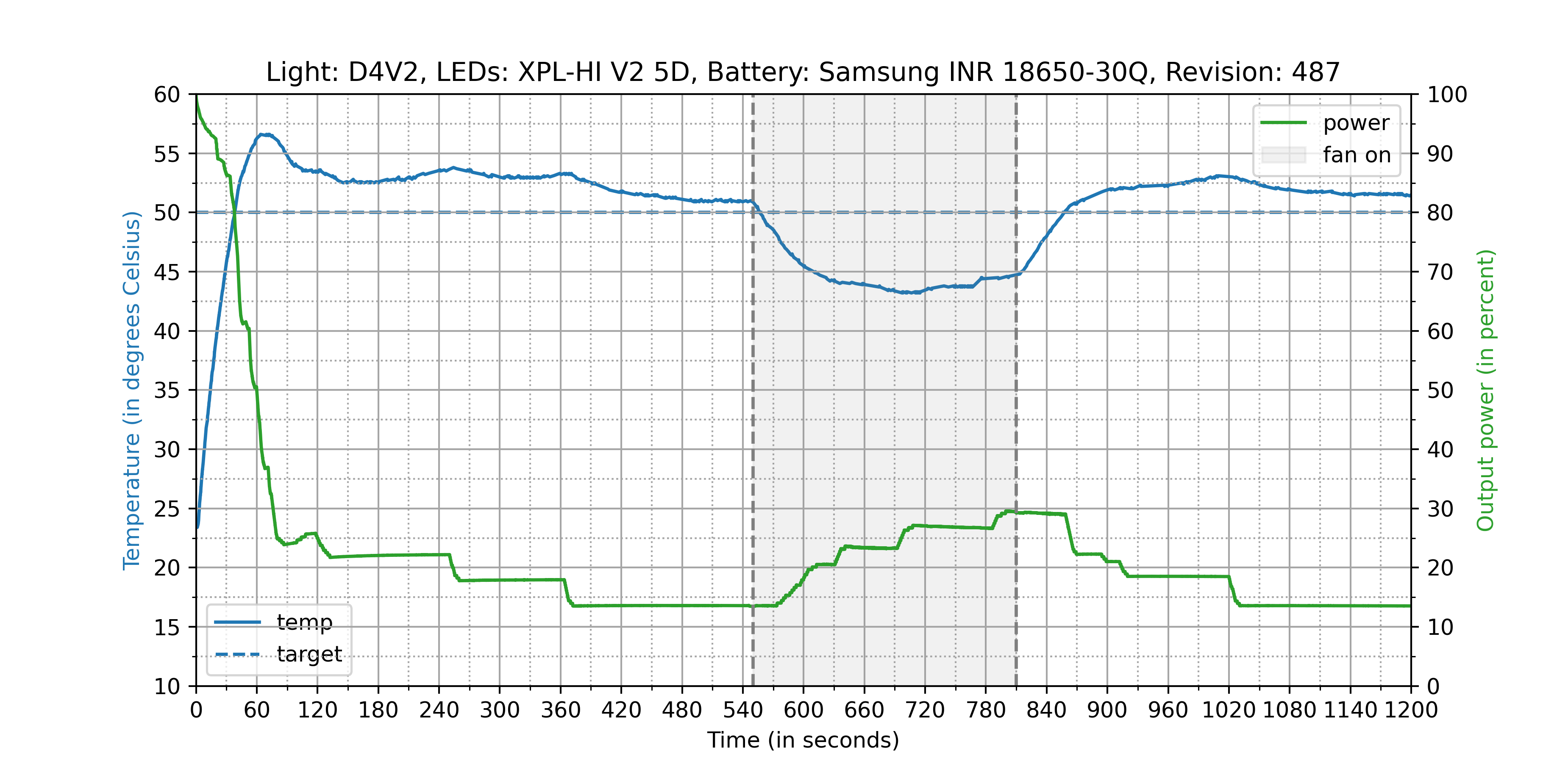

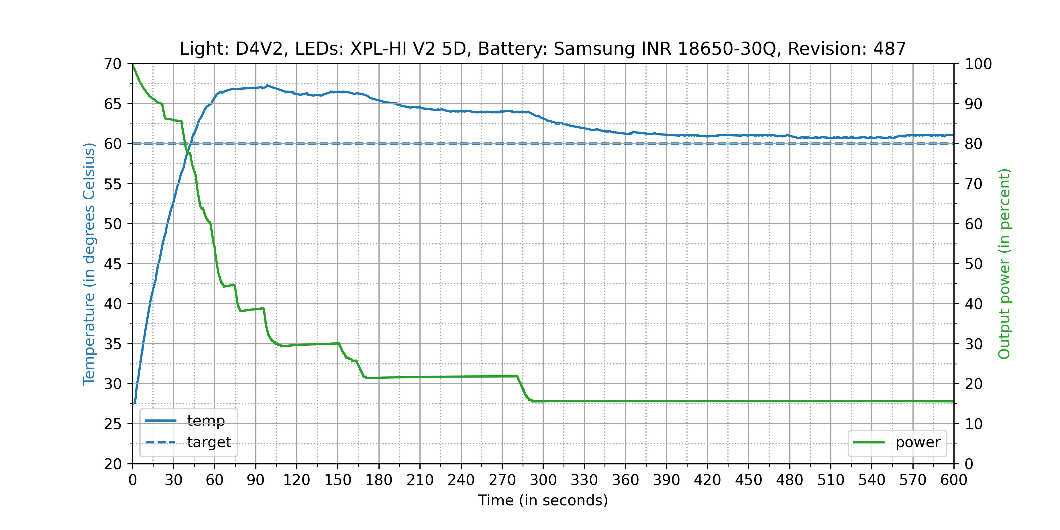

I’d say it’s a major step forward, but it still overshoots the temperature target too much for my taste. The overshooting seems to become worse with higher temperature targets.
I have not had the time to try it out on my other D4(S)V2 lights yet. But for comparison, here is a graph of what the thermal regulation of the code in my merge request looked like:
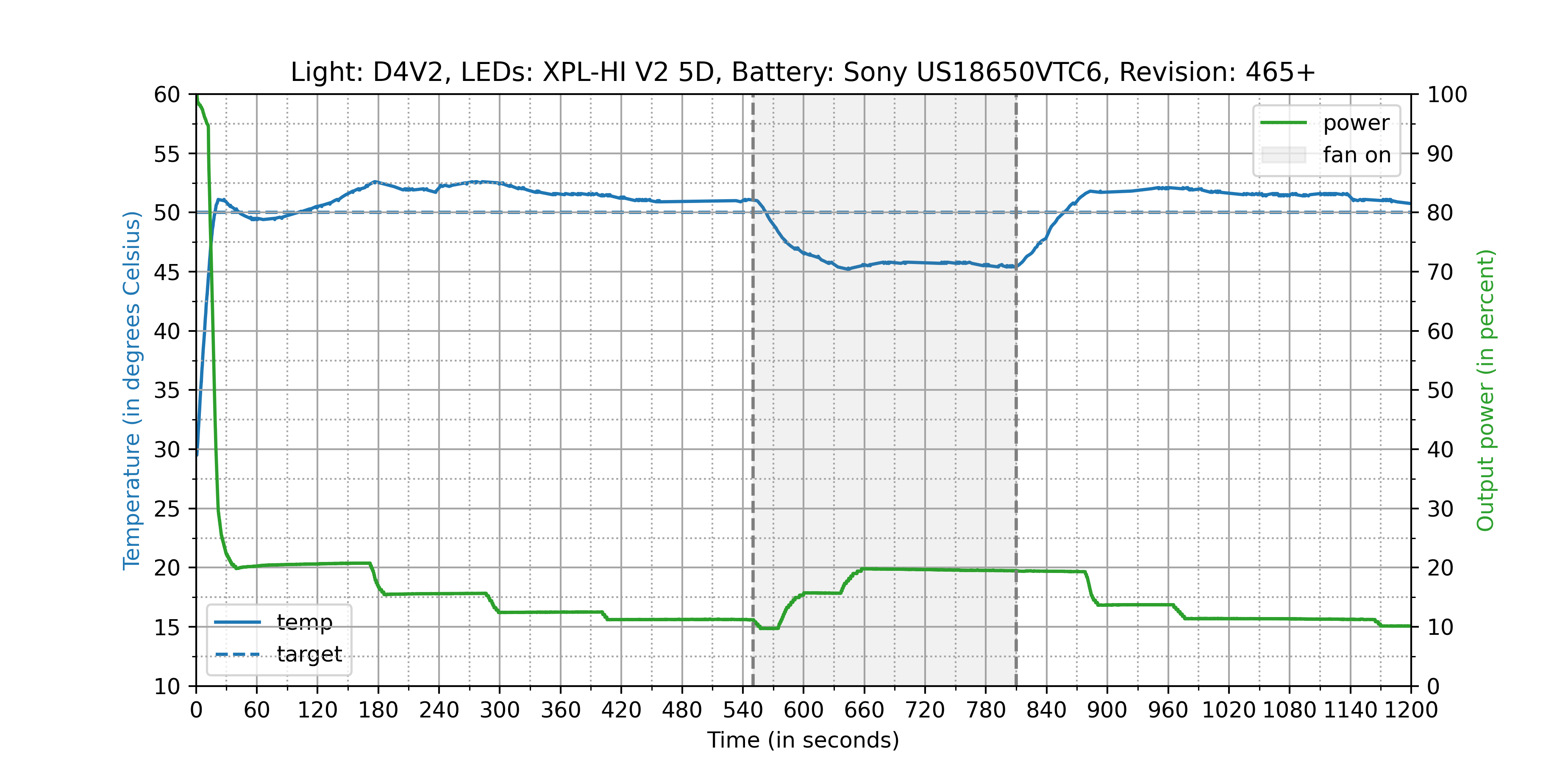
Another test with the new thermal regulation:
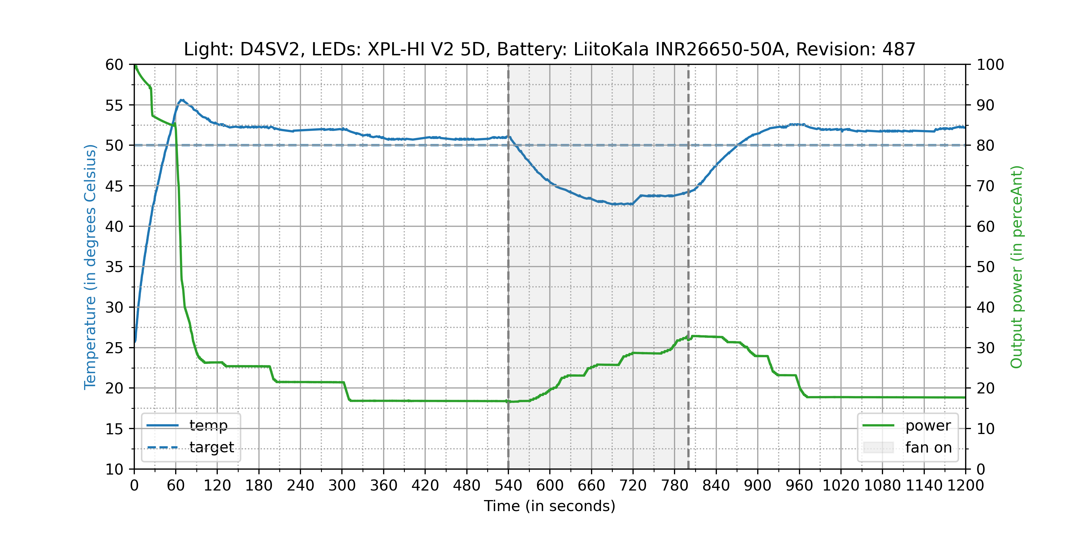

Bonus test:

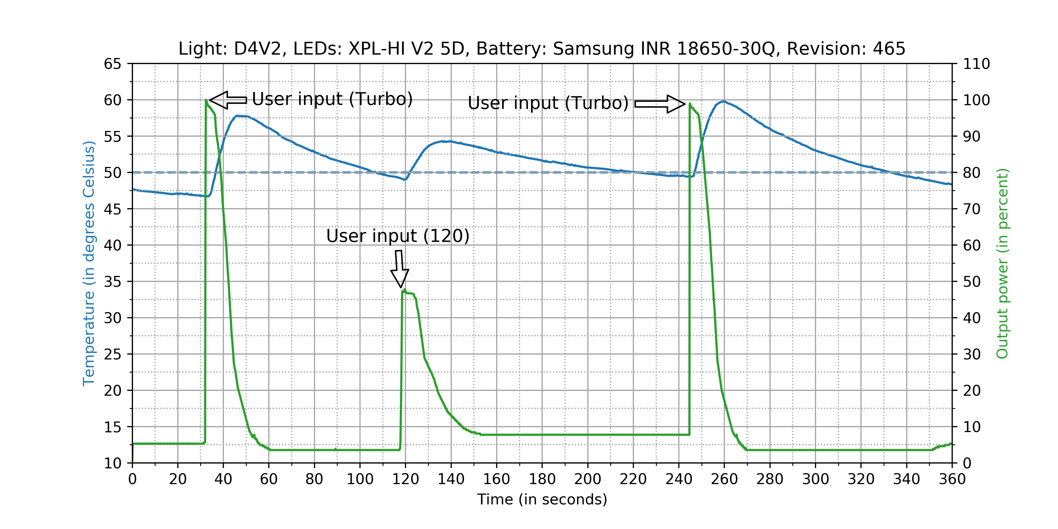
Thanks! This is incredibly helpful. I haven’t been able to run any thermal tests lately, and it’s really useful to see the results compared to the best known version.
It could definitely still use some improvement, but it looks like it’s a significant improvement from before. ![]()
Lately I’ve been focusing mostly on getting Anduril 2 ready. It’s basically done; I just keep procrastinating about finishing the diagrams and tutorial.
That’s right, and the more I use it, the more I like it.
Hi,
Will baton firmware work on a BLF A6 driver (17DD+1)?
No, the BLF-A6 driver uses an attiny13 chip, which does not have enough ROM to fit the Baton firmware. It also is not designed for use in e-switch hosts.
I’m experimenting with using lower PWM frequency (2kHz) in Anduril and am having a strange problem. I started the discussion in the attiny 25/45/85 development thread
I am using FET+1 drivers used in the V1 D4 and D1S which use attiny85. I want to use the lower PWM frequency because I am using a CN5710 regulator chip which wants the lower frequency, but the same problem happens on a stock unmodded D1S driver.
I added a 8x divider to the timer by changing TCCR0B from 0x01 to 0x02 in the fsm-main file. Upon making this change the ramping and other operation is apparently normal while the light is on, but I’m observing the following problems:
When turning on, the LED blinks at a very low brightness as you press the button then goes to the memorized level when you release the button. Whereas during proper operation the LED stays off until you release the button.
Sometimes when attempting to turn the light off it will instead go to the max 7135 channel level. But some part of the MCU thinks it is in fact off, because the next button click will always go to the previously memorized mode as if it was just turning on. It really does seem random whether the light turns off or goes to the max 7135 channel level. But the probability of it malfunctioning goes up with the PWM duty cycle. If I’m low in the 7135 channel duty cycle it usually turns off as it should, but if I’m high up in the 7135 channel duty cycle it usually malfunctions and goes to 7135 channel max level.
RampingIOS v3 does have the same problem.
RampingIOS v2 (in TomE’s folder) does not have the problem.
Does anyone know what the problem is and can it be fixed?
I’ve been fiddling with the Anduril 2 code for a while now and I just don’t quite understand the eeprom management. If there is a way to set a hybrid memory step and a timer I would appreciate some guidance when someone has time.
I still don’t know what you mean. There are already various timers and memory slots. Can you explain a bit more what you want to do?
I want to have a factory default setting embedded in my firmware that when a factory reset is performed it will set the Anduril 2 hybrid memory to step 3 with a 10 minute timer.
I’m assuming this is possible as a eeprom value is set for the AUX light defaults, I just don’t know the syntax otherwise or where to place it.
Add this to your config:
#define DEFAULT_MANUAL_MEMORY 50
#define DEFAULT_MANUAL_MEMORY_TIMER 10
This sets it to level 50/150 and 10 minutes timeout.
Oh wow, I’m not sure why I was overcomplicating it so much. I thought the value was something I had to embed in the eeprom.
I’ll give this a shot, thank you!
Edit: do you remember where the defines are that pull this into FSM code?
Edit2: found it in ramp-mode.h lines 150-157
It is used in ramp-mode.h
ToyKeeper (or maybe gchart or someone with repository access/knowledge):
I would like to get a change into FSM/Anduril 2 repository base line, file: fsm-main.c
The change:
- for the ATtiny25/45/85, any of the up to 3 supported channels can be mapped to pin #3, not just the third channel
I needed this for a couple specific drivers, can't recall which ones, but maybe from OSHPark or a manufacturer design, not sure.
You can see below that only the 3rd channel has the special support for PB4 (pin #3). The "new code" supports PB4 for any of the 3 channels. Maybe the same thing could be done to support pin #7 as a output channel - that would be nice as well. There's maybe a better way of doing this, cleaner, more elegant - my code is more brute force. let me know if this sounds ok, and do-able. I've been using it locally for quite a while.
Current code:
#if (ATTINY == 25) || (ATTINY == 45) || (ATTINY == 85)
static inline void hw_setup() {
    // configure PWM channels
    #if PWM_CHANNELS >= 1
    DDRB |= (1 << PWM1_PIN);
    TCCR0B = 0x01; // pre-scaler for timer (1 => 1, 2 => 8, 3 => 64...)
    TCCR0A = PHASE;
    #endif
    #if PWM_CHANNELS >= 2
    DDRB |= (1 << PWM2_PIN);
    #endif
    #if PWM_CHANNELS >= 3
    // Second PWM counter is ... weird
    DDRB |= (1 << PWM3_PIN);
    TCCR1 = _BV (CS10);
    GTCCR = _BV (COM1B1) | _BV (PWM1B);
    OCR1C = 255;  // Set ceiling value to maximum
    #endif
New code:
#if (ATTINY == 25) || (ATTINY == 45) || (ATTINY == 85)
static inline void hw_setup() {
// configure PWM channels
#if PWM_CHANNELS >= 1
DDRB |= (1 << PWM1_PIN);
TCCR0B = 0x01; // pre-scaler for timer (1 => 1, 2 => 8, 3 => 64...)
TCCR0A = PHASE;
#if (PWM1_PIN == PB4)
TCCR1 = _BV (CS10);
GTCCR = _BV (COM1B1) | _BV (PWM1B);
OCR1C = 255; // Set ceiling value to maximum
#endif
#endif
#if PWM_CHANNELS >= 2
DDRB |= (1 << PWM2_PIN);
#if (PWM2_PIN == PB4)
TCCR1 = _BV (CS10);
GTCCR = _BV (COM1B1) | _BV (PWM1B);
OCR1C = 255; // Set ceiling value to maximum
#endif
#endif
#if PWM_CHANNELS >= 3
// Second PWM counter is ... weird
DDRB |= (1 << PWM3_PIN);
#if (PWM3_PIN == PB4)
TCCR1 = _BV (CS10);
GTCCR = _BV (COM1B1) | _BV (PWM1B);
OCR1C = 255; // Set ceiling value to maximum
#endif
#endif</code></pre>