I wonder if the boost driver he has for single emitters is as good? I have a dm11 with xhp50.3. I know it’s a heck of a lot more efficient than the fet driver in my ts21. Lol. Went for an hour walk last night, mostly at 322 lumens (mode 5) with occasional turbo boosts, and I’m still at magenta so over 4.1v. And my charger stops at 4.16 so it just sips power. Checked with MM and 5000mah cell is at 4.1v
BTW “pwm” also visible on water drops at all L modes and even in M4.
L4 has low frequency flickering, too weak to measure by opple, but I think 50-100Hz.
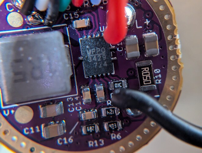
In this case, with this newer boost driver’s R10 being R050 and R4 being 120k, would I swap R4 to ~86k or is my math completely wrong? I’ve been scribbling on sticky notes for an hour lol
For what target current ?
With 84k, Vsense=2.8×4.7/(4.7+84)= 145mV and Iout = 145/50= 2.9A
But 1) 145mV is too high, 1.22W power loss in the sense resistor.
2) the inductor can’t handle 2.9A12V
Okay I was overthinking it ![]() I was aiming for 2.5 (max for this inductor?) which would be 100k then. I might actually swap out the inductor, what would be the highest current you recommend with the XAL7030? I also have no qualms about digging into the shelf if a taller one would help with efficiency, if there’s a taller one that’ll fit the footprint.
I was aiming for 2.5 (max for this inductor?) which would be 100k then. I might actually swap out the inductor, what would be the highest current you recommend with the XAL7030? I also have no qualms about digging into the shelf if a taller one would help with efficiency, if there’s a taller one that’ll fit the footprint.
Can anyone share data for the efficiency of the TS10 please?
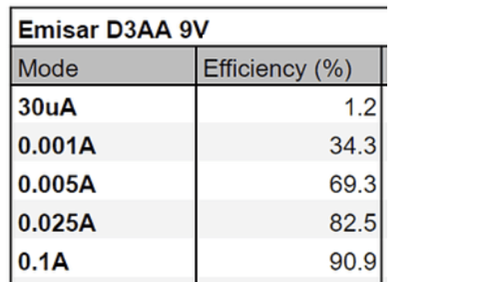
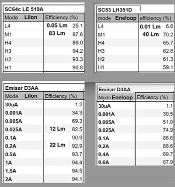
I want to compare it to the D3AA, for which there is this data:
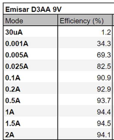
Im trying to find out at what Lumen level the TS10 is more efficient than the D3AA
because the TS10 uses PWM dimming (and an unregulated channel) it’s virtually impossible to compare unless doing a full system efficacy comparison : measuring power in and lumen out.
thank you
is it correct that the TS10 is regulated below the max 7135? (about 100 lumens)
any idea how many lumens the D3AA output is for any of these power levels?:
Im trying to figure out below what Lumen level the TS10 will have longer runtime than the D3AA.
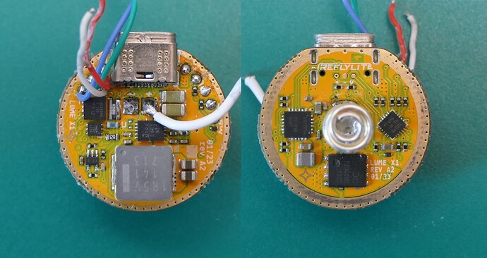
Lume X1 (X1S) :
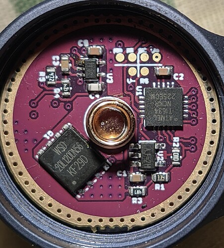
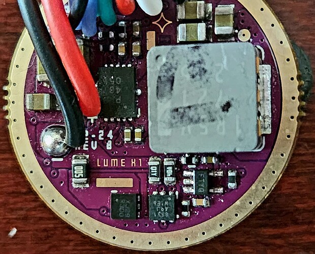
This is a Lume X1 boost driver designed by Loneoceans from a Fireflylite X1S, it uses a MP3431 boost converter with a relatively large 1.5uH inductor (~8x8x4mm).
The reverse polarity protection PFET is a Diodes Inc. DMP2002UPS, one of the best currently available.
A large dynamic range (”UDR”) is achieved with 3 sense resistors, turned on/off by a CSD16340Q3 NFET and a smaller double NFET.
The microcontroller is an Attiny1616, its DAC is used to control the output.
The charge controller is BQ25616 (unchanged from the first FFL Lume drivers).
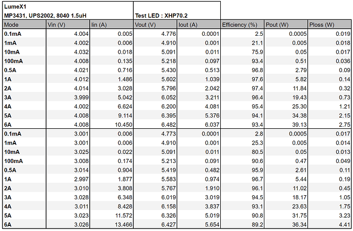
The efficiency results are good and expected from these components. The MP3431 was chosen instead of the TPS61288 that Loneoceans used in the first LumeX1 showcase. In my experience the MP343x behaves better thermally at ~40W and higher than the TPS61288 which tends to reach thermal protection rather easily.
Here the MP3431’s Ultrasonic mode is used to prevent the switching frequency going in the audible range at the cost of lower efficiency in low modes. With the TPS61288 the ceramic capacitors can sing in the audible range and at very low output the switching frequency can go down very low, making the LED visibly flicker. So a good choice I think.
That said there are two small ranges in the ramp where the driver whines a bit, likely due to a compensation capacitor for the Op-Amp not large enough (this is a particular quirk of the MP343x), a larger comp cap may make the sense resistors transitions more visible though, so there is a compromise to be made here, ultimately once the driver is inside the light the whine is quite low.
One odd choice is the high range sense resistor FET, CSD16340Q3 has a fairly high on resistance (~5mΩ) relatively to the shunt resistor (5mΩ) and it varies non negligibly from 4.2Vin to 2.8Vin. Thus you get this output variation depending on the input voltage, nearly 0.4A lower at max output at 3Vin vs 4Vin. Due to Rdson variation between parts, the output current will vary more between drivers, and heat dependent Rdson increase makes the output drops more as the driver heats up.
There are other similarly priced FETs on the market that would have been a better choice and would have reduced these variations.
Thank you!
I’m looking forward to testing this one in the X1S. Bice to see it’s driving the LED pretty hard at max
Thank you for your tests and nice job!
I ask for advice, I’m a noob in this business myself, but I know how to solder ![]()
Can the d4k 12v 2A boost driver be converted to 6v 4A If so, what components need to be replaced on it? As far as I understand, reducing the voltage will not only allow you to work with the b35Am (I also have one substrate from Clemence), but will also increase efficiency?
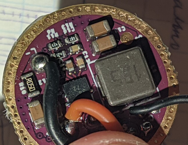
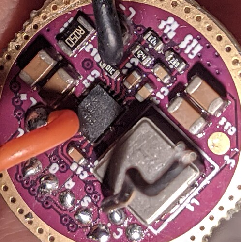
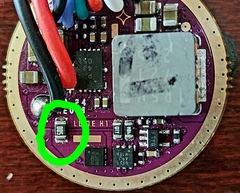
For doubling the current, the sense resistor (R10) needs to be halved, either by replacing it with 25mΩ or by solderding another 50mΩ on top of the original one.
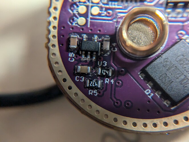
To change the output range for a 6V LED, the resistor with ”124” marking (120k) next to the negative wire needs to be replaced with womething like 51k.(if I’m seeing right).
Edit : in some case the output can be unstable at 6Vout at 4A or above with the default compensation resistor ( ”682” marking : 6.8k), lowering it to 4.7k or 3.3k is usually better (although it’s u’changed in the 6V4A driver).
I’m confused why you lowered the driver voltage for efficiency. I ordered the X1 in stock from jlhawaii808 which I intend to mod for a 6V 1.2A LED.
I asked Jackson whether I should get the “6V 6A” or the “9V 3A” and he said always higher voltage will be more efficient. So I ordered the 9V 3A. Should I have gotten the 6V driver?
Also, the sense resistor on the 9V 3A appears to be “005” or 0.005 ohm? If I replace with 0.0125 ohm, output should reduce to 1.2A?
Bit of a late reply but if you’re still wondering about the efficiency; there’s a few different factors in play here. Boost drivers are generally more efficient when Vin is close to Vout, so reducing the Vout from 12V to 6V will increase the efficiency of the boost circuit. However, at a higher Vout the current flowing through all of the wiring after the driver is lower, and so there’s less resistive heating.
I’ve no idea which one has a greater effect and it depends on how the light is constructed, but it’s probably a few percentage points here or there.
adding D3AA data to compare to my Zebras
(D3AA output by power level from zeroair and 1lumen reviews data, Zebra outputs from website)
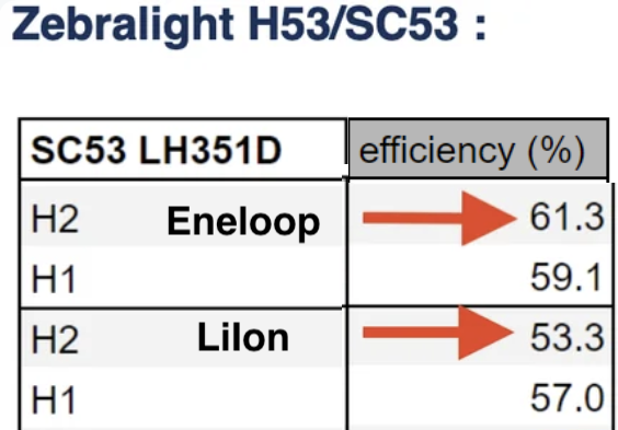
btw, SC53 on H2 is more efficient with Eneloop than LiIon:
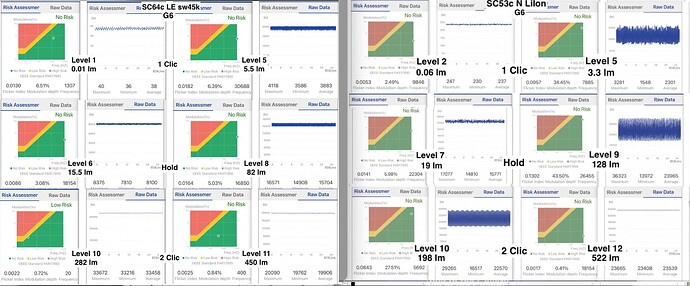
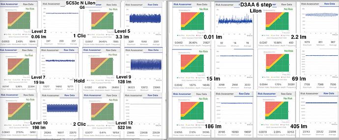
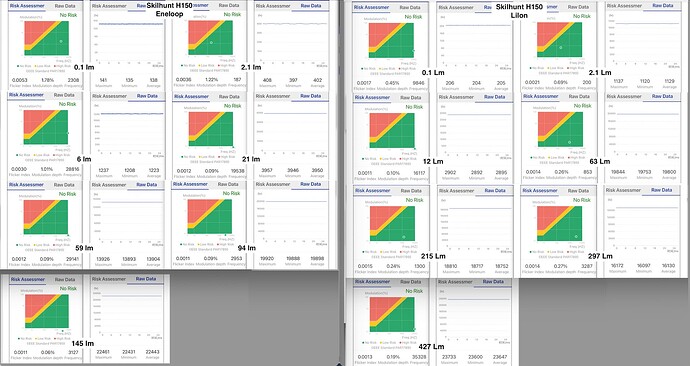
Opple Flicker Index for
SC64 and SC53:
and SC53 and D3AA set to 6 steps:
Skilhunt H150:
If I’m not mistaken there’s a line under the digits, meaning the resistor value is .005 Ohm.
